AIRLESSCO SL1100 Series A Operation - Repair - Parts
Airless paint sprayer
Hide thumbs
Also See for SL1100 Series A:
- Service & operation manual (32 pages) ,
- Operation and repair manual (37 pages) ,
- Service & operation manual (36 pages)
Table of Contents
Advertisement
Operation/Repair/Parts
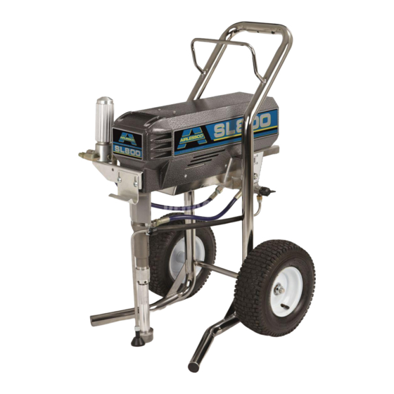
SL800/1100
Mustang 11000
Airless Paint Sprayer
For application of architectural paints and coatings. For professional use only. Not
approved for use in European explosive atmosphere locations.
3000 psi (20.7MPa, 207 bar) Maximum Working Pressure
Important Safety Instructions
Read all warnings and instructions in this
manual. Save these instructions.
Related Manuals
Gun Manual
312363 - English
312364 - Spanish
312365 - French
Airlessco SL800 Series A
Airlessco SL1100 Series A
Airlessco SL1100 Series B
AllPro Mustang 11000 Series B
Model
Part Number
16M376
16M383
16M377
16M384
16M394
24F572
24F584
Voltage
240V
110V
240V
110V
230V
120V
120V
3A1184G
EN
ti17344a
Advertisement
Table of Contents

Related Manuals for AIRLESSCO SL1100 Series A


Summary of Contents for AIRLESSCO SL1100 Series A
- Page 1 Save these instructions. Related Manuals Gun Manual 312363 - English 312364 - Spanish 312365 - French Model Part Number Voltage 16M376 240V Airlessco SL800 Series A 16M383 110V ti17344a 16M377 240V Airlessco SL1100 Series A 16M384 110V 16M394 230V...
- Page 2 Warnings Warnings The following warnings are for the setup, use, grounding, maintenance, and repair of this equipment. The exclama- tion point symbol alerts you to a general warning and the hazard symbols refer to procedure-specific risks. When these symbols appear in the body of this manual or warning labels, refer back to these Warnings. Product-specific hazard symbols and warnings not covered in this section may appear throughout the body of this manual where applicable.
- Page 3 All parts of the spray system, including the pump, hose assembly, spray gun, and objects in and around the spray area shall be properly grounded to protect against static discharge and sparks. Use Airlessco conductive or grounded high-pressure airless paint sprayer hoses.
- Page 4 • Do not kink or over-bend the hose. • Do not expose the hose to temperatures or to pressures in excess of those specified by Airlessco. • Do not use the hose as a strength member to pull or lift the equipment.
- Page 5 Warnings WARNING WARNING WARNING WARNING MOVING PARTS HAZARD Moving parts can pinch, cut or amputate fingers and other body parts. • Keep clear of moving parts. • Do not operate equipment with protective guards or covers removed. • Pressurized equipment can start without warning. Before checking, moving, or servicing equipment, follow the Pressure Relief Procedure and disconnect all power sources.
-
Page 6: Component Identification
Component Identification Component Identification ti17345a Power switch Turns sprayer ON and OFF Pressure Control Knob Adjusts pressure. Turn clockwise to increase pressure and counterclockwise to decrease pressure. Drain Valve Primes pump and relieves pressure from gun, hose and tip. Drain Valve Open Position Relieves pressure from gun, hose and tip and primes the unit when in the open position. -
Page 7: Operation
Operation Operation Pressure Relief Procedure 5. Re-engage gun trigger lock and close Prime/Pres- sure Relief Valve. To reduce risk of injury, follow this pressure relief pro- cedure whenever you see this symbol throughout this manual, Also, perform this procedure whenever you: •... -
Page 8: Prime And Flush Storage Fluid
Operation Fill the Packing Nut/Wet Cup Flushing 1. Fill the Packing Nut/Wet Cup with 5 drops of Air- lessco Throat Seal Oil (TSO). • To reduce the risk of static sparking, which can cause fire or explosion, always hold a metal part of the gun firmly against the metal pail when flushing. - Page 9 Operation 6. Turn the engine ON/OFF switch to ON. Startup 7. Point the gun into the metal pail and hold a metal 1. Prepare the material according to the material man- part of the gun firmly against the pail. Maintain firm ufacturer’s recommendations.
-
Page 10: Adjusting The Pressure
• To reduce the risk of injection, never hold your solvent such as mineral spirits or Graco or Airlessco hand, body, fingers or hand in a rag in front of the Pump Armor. -
Page 11: Regular Maintenance
2. Keep displacement pump packing nut/wet cup 1/3 Motor Brushes full of Airlessco Throat Seal Oil at all times. The TSO helps protect the packings and rod. Motor brushes need periodic inspection and replace- ment as wear indicates. -
Page 12: Replacement Of Belt/Belt Adjustment
Maintenance Replacement of Belt/Belt Servicing the Fluid Pump Adjustment NOTE: Before disassembling the sprayer refer to Trou- bleshooting to try and resolve the problem. NOTE: The Cog Belt System does not require align- ment. When upper sheave is placed on motor shaft it is Fluid Pump Disconnect pushed on until a positive stop is reached. - Page 13 Maintenance Fluid Pump Reinstall 4. Remove the retaining ring from the packing nut and insert into coupling halves. 1. Loosen the packing nut and extend piston rod to fully up position. Slip sleeve over the piston rod. ti15994a ti15998a 2. Insert one of the retaining rings through the packing 5.
-
Page 14: Servicing Inlet Nut And Outlet Valve
Maintenance Servicing Inlet Nut and Outlet Valve Inlet Valve 1. Using the rod collar tool (865008), unscrew the suc- tion nut (16), containing suction seat (13), off of the fluid body. 2. Remove suction seat (13), O-ring (15), suction ball (11) and suction ball guide (10). -
Page 15: Packing Replacement Procedures
Maintenance Packing Replacement Procedures Disassembly of the Fluid Pump 6. Take assembled glands and packings (13 pieces) and slide onto the lower half of the piston. 1. Unscrew and remove the packing nut (2). 7. Take the spacer (4) and slide over the top of the pis- 2. - Page 16 Maintenance 17. Thread the packing nut (2) into the top of the fluid body (3) and tighten hand tight. 18. Take the suction retainer (10) and replace the black O-ring (15) with a new one from the packing kit. Replace the suction ball (11) with a new one from the kit into the suction retainer (10).
-
Page 17: Replacement Of Electrical Components
Maintenance Replacement of Electrical Components Always unplug the electrical cord before servicing the machine. NOTE: Anytime the pressure control assembly, sensor, On-Off Toggle Switch or both are replaced, perform the calibrations. 1. Lower the pressure control assembly as described above. Pressure Control Assembly (Electrical Control Board) 2. -
Page 18: Troubleshooting
Troubleshooting Troubleshooting General Problem Cause Solution Unit doesn’t prime Airleak due to loose suction nut Tighten suction nut. Airleak due to worn o-rings Replace o-ring (110636) on suction seat and o-ring (867390) below suction seat. Stuck or fouled balls Service inlet and outlet valves. Prime/Pressure Relief valve Clean or replace Prime Valve (866428) not opening... - Page 19 Troubleshooting Problem Cause Solution Motor Remove the motor brush covers and turn the machine ON. Set the potentiometer (POT) at maximum pressure and check for DC voltage across both brush terminals. It should read greater than 80 volts DC. If you have DC voltage, turn the machine off and unplug it from the wall.
- Page 20 Troubleshooting Problem Cause Solution Pattern too narrow Spray angle too small Use larger spray angle tip (if coverage is OK, try tip in same tip group) Too much material Tip too large Use smaller tip Material too thin Use smaller tip Pressure too high Reduce pressure Too little material...
-
Page 21: Pressure Control Repair
Troubleshooting Pressure Control Repair Motor Control Board Diagnostics 1. For sprayers with digital display, seeDigital Display Messages, page 22 2. Remove screws and cover. Relieve pressure and unplug sprayer before servicing control board. See Pressure Relief Procedure, 3. Turn ON/OFF switch ON. page 7. - Page 22 Troubleshooting Digital Display Messages (Series B) No display does not mean that spayer is not pressurized. Relieve pressure before repair. See Pressure Relief Procedure, page 7 DISPLAY SPRAYER OPERATION INDICATION ACTION No Display Sprayer stops. Power is Loss of power. Check power source.
-
Page 23: Manifold Filter
Parts Parts Manifold Filter (865627) ti16052a Ref. Part Description Qty. Ref. Part Description Qty. 867145 BASE 867077 BASE 301356 SPRING 867004 SWIVEL (not shown) 867377 O-RING 867420 PLUG 3/8” 867214 FILTER 60 MESH 867309 NIPPLE 3/8”M x 1/4”M 867647 SUPPORT 557391 PLUG 1/4”... -
Page 24: Control Parts Diagram
Parts Control Parts Diagram ti17478b 120* CONTROL,BOARD 243222 TRANSDUCER,PRESSURE CON- 121* 867796 GASKET,COVER SL TROL 122* HEAT SINK,MACHINED SL 866049 CABLE,ASSY 9” LG 125* SPACER,CONTROL BOARD 110637 SCREW,MACH,PANHEAD 126* SCREW,MACH,PHILLIPS PAN HD 557391 PLUG,DRYSEAL 1/4 NPTF 129* 100272 WASHER,LOCK 867311 FITTING,NIPPLE HX 3/8 TO 3/8 CONTROL BOARD KIT (includes 38, 120, 121, 122, 125, 126, 129) 301308 HOSE,3/8 X 16 LONG... - Page 25 Parts Notes 3A1184G...
- Page 26 Parts Frame Parts Diagram ti17476b ti17877a 3A1184G...
- Page 27 Parts Ref. Part Description Qty. Ref. Part Description Qty. 256219 POTENTIOMETR,ASSEMBLY 4▲ 342425 LABEL - HIGH VOLTAGE 866049 CABLE,ASSY 9” LG 15H550 LABEL,SERIAL 331185 STRAIN RELIEF 867791 FRAME,CART 110637 SCREW,MACH,PANHEAD 301134 PLUG,NEOPRENE 867252 GROMMET 143029 COLLAR,SCREW,SET (SPECIAL ID) 301165 WHEEL,PNEUMATIC 289316 (SL1100) 120V 866025...
-
Page 28: Motor And Drive Parts Diagram
Parts Motor and Drive Parts Diagram ti17894a ti17587a 3A1184G... - Page 29 16F579 LABEL,AIRLESSCO, SL1100, LEFT 301004 TUBE,SUCTION 16F741 LABEL, ALLPRO, MUSTANG 141010 FILTER,BASKET, 1” NPTF 11000, LEFT 866267 PISTON,PUMP, 2.00 STROKE 16H954 LABEL, AIRLESSCO, SL800, LEFT 867641 STUD,3/8-16 X 6-1/2 LG 301059 SPACER,SL SERIES 866211 CLIP,J 301467 SHIELD FRONT SL SERIES 305140 BRACKET,BRACKET- FILTER 867140 COUPLER, 331103 WASHER .562 .250 .060 .ST...
-
Page 30: Packing Replacement
Parts Packing Replacement Ref. Part Description Qty. PISTON,2.00 STROKE, SL 866056 SCREW,COLLAR 866295 BODY,PUMP,MACHINING 866362 SPACER,TUBE 5*+ 104319 PACKING,O-RING 6*+ 866307 RETAINER,BALL,.3125,SL 867047 BALL,.3125, GR25, PISTON 867575 SEAT,UPPER,T.C. 866274 PLUG,3/4-20 866306 RETAINER,SUCTION 11+ 101822 BALL, INTAKE 866400 SUPPORT,SUCTION SEAT 867574 SEAT,T.C. 14+ 867390 O-RING,5-677, PTFE 15+ 556562 O-RING,-121 VITON-A 75 DURO 866241 NUT,SUCTION... -
Page 31: Suction Assemblies
Parts Suction Assemblies Ref. Part Description Qty. 301594 SUCTION ASSEMBLY (includes 2) 1 187147 INLET STRAINER 241920 THREADED DEFLECTOR 867759 MALE CONNECTOR 867758 DRAIN HOSE (includes 4) 866211 CLIP 24D688 RETURN HOSE ASSEMBLY includes 3, 4, 5 ti16147a 3A1184G... -
Page 32: Electrical System
Parts Electrical System Black ON/OFF Black Switch Power Plug Black White Green Black (+) Black (-) from Motor 2 x Red ti2471b Ref. Part Description Qty. Ref. Part Description Qty. CORD 301083 TOGGLE SWITCH 331168 120V PRESSURE CONTROL ASSEMBLY 118046 110V 243222 TRANSDUCER... -
Page 33: Technical Data
Technical Data Technical Data Power requirements ........120V AC, 60 hz, 11A, 1 phase 230V AC, 50/60 Hz, 7.5A, 1 phase Generator required . -
Page 34: Airlessco Standard Warranty
With the exception of any special, extended, or limited warranty published by Airlessco, Airlessco will, for a period of twelve months from the date of sale, repair or replace any part of the equipment determined by Airlessco to be defective.
Need help?
Do you have a question about the SL1100 Series A and is the answer not in the manual?
Questions and answers