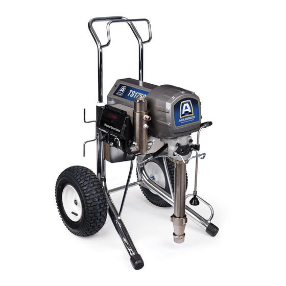
AIRLESSCO SL1250 Operation - Repair - Parts

AIRLESSCO SL1250 Operation - Repair - Parts

Electric airless sprayers

Advertisement

Operation/Repair/Parts
SL1250, TS1750, Mustang 11500
Electric Airless Sprayers
For professional use only.
Not approved for use in explosive atmospheres or hazardous locations.
For portable spray application of architectural paints and coatings.
3300 psi (22.7 MPa, 227 bar) Maximum Working Pressure

Important Safety Instructions

Read all warnings and instructions in this manual and in related manuals.
Be familiar with the controls and the proper usage of the equipment.
Save these instructions.
Related Manuals:
Gun
Pump
SL1250 / Mustang 11500
3A4133
333028
3A4147B
TS1750
3A0413
333028
EN
ti29385a

Advertisement

Table of Contents
loading
Need help?

Need help?

Do you have a question about the SL1250 and is the answer not in the manual?

Questions and answers

Subscribe to Our Youtube Channel

Summary of Contents for AIRLESSCO SL1250

  • Page 1: Important Safety Instructions

    Operation/Repair/Parts SL1250, TS1750, Mustang 11500 3A4147B Electric Airless Sprayers For professional use only. Not approved for use in explosive atmospheres or hazardous locations. For portable spray application of architectural paints and coatings. 3300 psi (22.7 MPa, 227 bar) Maximum Working Pressure Important Safety Instructions Read all warnings and instructions in this manual and in related manuals.
  • Page 2 Voltage SL1250 -NA 17M140* TS1750 -NA 17M145 120V TS1750 Hose Reel - NA 17M147 AllPro Mustang 11500 Hiboy - NA 17M155* SL1250 - AP/SCA 17M243 TS1750 - AP/SCA 17M244 240V TS1750 Hose Reel - AP/SCA 17M245 * ETL listed 3A4147B...
  • Page 3: Table Of Contents

    SL1250, TS1750, Mustang 11500 Parts ....38 SL1250 and Mustang 11500 ......39 TS1750 .
  • Page 4: Warnings

    Warnings Warnings The following warnings are for the setup, use, grounding, maintenance, and repair of this equipment. The exclamation point symbol alerts you to a general warning and the hazard symbols refer to procedure-specific risks. When these symbols appear in the body of this manual or on warning labels, refer back to these Warnings.
  • Page 5 Check hoses and parts for signs of damage. Replace any damaged hoses or parts. • This system is capable of producing 3300 psi. Use Airlessco replacement parts or accessories that are rated a minimum of 3300 psi. • Always engage the trigger lock when not spraying. Verify the trigger lock is functioning properly.
  • Page 6: Fire And Explosion Hazard

    All parts of the spray system, including pump, hose assembly, spray gun, and objects in and around the spray area shall be properly grounded to protect against static discharge and sparks. Use Airlessco conductive or grounded high-pressure airless paint sprayer hoses.
  • Page 7 Do not kink or over-bend the hose. • Do not expose the hose to temperatures or to pressures in excess of those specified by Airlessco. • Do not use the hose as a strength member to pull or lift the equipment.
  • Page 8 Warnings MOVING PARTS HAZARD Moving parts can pinch, cut or amputate fingers and other body parts. • Keep clear of moving parts. • Do not operate equipment with protective guards or covers removed. • Pressurized equipment can start without warning. Before checking, moving, or servicing equipment, follow the Pressure Relief Procedure and disconnect all power sources.
  • Page 9: Component Identification

    Component Identification Component Identification Standard Models (SL1250 & TS1750) Filter AMP Switch (not available on all units) Strainer ON/OFF Switch Pump Pressure Control Drain Tube Prime / Spray Valve Model/Serial Tag Trigger Lock 3A4147B...
  • Page 10: Component Identification

    Component Identification Component Identification TS1750 Hose Reel ti29387b Filter Display Strainer Amp Switch (not available on all units) Pump ON/OFF Switch Unit / Serial Tag Pressure Control Drain Tube Spray / Prime QuickReel Trigger Lock 3A4147B...
  • Page 11: Grounding

    Grounding Grounding Do not modify plug! If it will not fit in outlet, have grounded outlet installed by a qualified electrician. Do not use an adapter. This equipment must be grounded to Power Requirements reduce the risk of static sparking and electric shock.
  • Page 12 Grounding Pails To maintain grounding continuity when flushing or relieving pressure: hold metal part of spray gun firmly to side of a grounded metal pail. Then trigger gun. Solvent and oil-based fluids: follow local code. Use only conductive metal pails, placed on a grounded surface such as concrete.
  • Page 13: Pressure Relief Procedure

    Pressure Relief Procedure Pressure Relief Procedure Remove guard and SwitchTip. Follow the Pressure Relief Procedure whenever you see this symbol. ti29389a Turn pressure to lowest setting. Trigger This equipment stays pressurized until gun to relieve pressure. pressure is manually relieved. To help prevent serious injury from pressurized fluid, such as skin injection, splashing fluid and moving parts, follow the Pressure...
  • Page 14: Setup

    Setup Setup Connect swivel (TS1750) and gun to other end of hose. Tighten securely. All sprayers except hose reel: Connect ti18195a airless hose to sprayer. Tighten securely. Engage trigger lock. ti28776b Remove tip guard. ti29664a If using the optional hopper, remove the nipple fitting from the filter.
  • Page 15 Setup Fill throat packing nut with Throat Seal Turn prime valve down to DRAIN position. Oil to prevent premature packing wear. Do this each time you spray. ti14842a ti29665a 10. Place pump in grounded metal pail Turn power OFF. partially filled with flushing fluid. Attach ground wire to pail and to true earth ground.
  • Page 16: Startup

    Startup Startup Increase pressure 1/2 turn to start motor and allow fluid to circulate through drain tube for 15 seconds; turn pressure down. 15sec Perform Pressure Relief Procedure, page 13. Turn pressure control to lowest pressure. Turn prime valve forward to SPRAY position.
  • Page 17 Startup Trigger gun again into flushing pail until paint appears. Move gun to paint pail and trigger for 20 seconds. High-pressure spray is able to inject toxins into the body and cause serious bodily injury. Do not stop leaks with hand or rag. Inspect for leaks.
  • Page 18: Switch Tip Installation

    Switch Tip Installation Switch Tip Installation Hold gun perpendicular, 10-12 in. (25-30 cm) from surface. Spray back and forth. Overlap by 50%. Trigger gun after moving and release before stopping. Perform Pressure Relief Procedure, page 13. ™ Use spray tip (A) to insert OneSeal into guard (C).
  • Page 19: Hose Reel

    Hose Reel Hose Reel Pull reel handle up and turn clockwise to reel in hose. ti13502b ti13503b Moving parts can pinch, cut or amputate fingers and other body parts. To avoid injury from moving parts, be sure to keep your head clear of hose reel while winding up hose.
  • Page 20: Digital Tracking System

    Digital Tracking System Digital Tracking System Change Display Units Press and hold button for 5 seconds to Operation Main Menu change pressure units (psi, bar, MPa) to desired units. Selection of bar or MPa Short press to move to next display. Press changes gallons to liters x 10.
  • Page 21: Secondary Menu - Stored Data

    RESISTOR scrolls by and model code Short press button and MOTOR HOURS number (see below). scrolls past and then total motor run hours are displayed. Motor ID Models Number SL1250 / Mustang 11500 TS1750 (230 V) TS1750 (120 V) 3A4147B...
  • Page 22: Cleanup

    Cleanup Cleanup Turn prime valve down to DRAIN position and allow flushing fluid to circulate until flushing fluid appears clear. Perform Pressure Relief Procedure, page 13, steps 1 - 4. Remove tip guard from gun. ti22945a NOTE: Use water for water-base material, Turn prime valve forward to SPRAY mineral spirits for oil-base material, or other position.
  • Page 23 Cleanup Remove filters from gun and sprayer, if 11. Wipe sprayer, hose and gun with a rag soaked in water or mineral spirits. installed. Clean and inspect. Install filters. ti13454a ti2776a ti15018a 10. If flushing with water, flush again with mineral spirits, or Pump Life, to leave a protective coating to prevent freezing or corrosion.
  • Page 24: Troubleshooting

    Troubleshooting Troubleshooting Perform Pressure Relief Procedure, page 13. PROBLEM CAUSE SOLUTION For units with display: Fault condition exists Determine fault correction from CODE XX is displayed. table, page 27. Pump output is low Spray tip worn Follow Pressure Relief Procedure on page 13, then replace tip.
  • Page 25 Troubleshooting PROBLEM CAUSE SOLUTION Pump output is low Pump rod damage Repair pump. See pump manual. Low stall pressure Turn pressure knob fully clockwise. Make sure pressure control knob is properly installed to allow full clockwise position. If problem persists, replace pressure transducer.
  • Page 26 Troubleshooting PROBLEM CAUSE SOLUTION Air in pump or hose Check and tighten all fluid Pump is difficult to prime connections. Cycle pump as slowly as possible during priming. Intake valve is leaking Clean intake valve. Be sure ball seat is not nicked or worn and that ball seats well.
  • Page 27 Troubleshooting Electrical Control Board Status Light Symptom: Sprayer does not run, stops running, or will not shut off. Perform Pressure Relief Procedure; page 13. Plug sprayer into correct voltage, grounded outlet. To determine error code for units without display, refer to the control board status Set power switch OFF for 30 seconds light.
  • Page 28 Troubleshooting PROBLEM CAUSE SOLUTION Sprayer does not run at all Check transducer or Make sure there is no pressure in transducer connections the system (see Pressure Relief Display shows CODE 02 Procedure, page 13). Check fluid path for clogs, such as clogged filter.
  • Page 29 Troubleshooting PROBLEM CAUSE SOLUTION Sprayer does not run at all Check transducer or Set sprayer to OFF and disconnect transducer connections power to sprayer. Display shows CODE 03 (control board is not detecting Check transducer and connections a pressure signal). to control board.
  • Page 30 Troubleshooting PROBLEM CAUSE SOLUTION Sprayer does not run at all Control is commanding motor Remove pump and try to run sprayer. to run but motor shaft does not If motor runs, check for locked or Display shows CODE 05 rotate. Possibly locked rotor frozen pump or drive train.
  • Page 31 Unplug thermal wires. Set meter to ohms. Meter should read the proper resistance for each unit (see table Control board status light below). blinks 5 times repeatedly Resistance Table: SL1250 / 11500 0 ohms TS1750 (240V) 3.9k ohms TS1750 (120V) 6.2k ohms 3A4147B...
  • Page 32 Check Motor Thermal Switch: Unplug thermal wires. Set meter to ohms. Meter should read the proper resistance for each unit (see table below). Resistance Table: SL1250 / 11500 0 ohms TS1750 (240V) 3.9k ohms TS1750 (120V) 6.2k ohms Reconnect thermal device connector to control board socket.
  • Page 33 Troubleshooting PROBLEM CAUSE SOLUTION Sprayer does not run at all Check voltage supply to the Set sprayer to OFF and disconnect sprayer (incoming voltage too power to sprayer. Display shows CODE 08 low for sprayer operation) Remove other equipment that uses the same circuit.
  • Page 34 Troubleshooting PROBLEM CAUSE SOLUTION Sprayer does not run at all Check the connections. Turn power OFF. Control is not receiving a Disconnect motor position sensor Digital display shows motor position sensor signal and inspect for damage at CODE 16 connectors. Control board status light ti18685a blinks 16 times repeatedly...
  • Page 35 Troubleshooting Sprayer Will Not Run (See following page for steps) Remove control box cover. Turn See step 1. Do See step 2. Do Repair or sprayer ON. Observe control you have over you have over replace power board status light on control 100 VAC (220 100 VAC (220 cord...
  • Page 36 Troubleshooting STEP 1: STEP 2: Plug power cord in and Plug power cord in and 200-240V 200-240V turn switch ON. Connect turn switch ON. Connect probes to on/off switch. probes to on/off switch. Turn meter to AC volts. Turn meter to AC volts. STEP 3: Check motor thermal switch.
  • Page 37: Sprayer Will Not Run

    Sprayer Will Not Run Sprayer Will Not Run Perform Pressure Relief Procedure, Remove control box cover so the control page 13. Leave prime valve open and board status light can be viewed if power switch OFF. available. Troubleshooting procedure: Plumb pressure gauge into paint Mechanical problem: See the proper hose, plug sprayer in, and turn fluid pump manual for the sprayer...
  • Page 38: Sl1250, Ts1750, Mustang 11500 Parts

    SL1250, TS1750, Mustang 11500 Parts SL1250, TS1750, Mustang 11500 Parts ti29385a 3A4147B...
  • Page 39: Sl1250 And Mustang 11500

    SL1250 and Mustang 11500 SL1250 and Mustang 11500 Ref. Torque Ref. Torque 25-30 ft-lb (33.8 - 40.6 N•m) 40-45 in-lb (4.5 - 5.0 N•m) 70-80 ft-lb (94.9 - 108.4 N•m) 9-11 in-lb (1.0 - 1.2 N•m) 15-20 in-lb (1.7 - 2.3 N•m) 200-230 in-lb (22.6 - 25.9 N•m)
  • Page 40 Parts List - SL1250 and Mustang 11500 Parts List - SL1250 and Mustang 11500 Ref. Part Description Ref. Part Description 248214 TUBE, intake, includes 109 15C753 SCREW, mach torx, hex 278204 CLIP, spring 15E891 CLIP, retaining 17B215 HOUSING, bearing, 156306...
  • Page 41: Ts1750

    TS1750 TS1750 Ref. Torque Ref. Torque 25-30 ft-lb (33.8 - 40.6 N•m) 40-45 in-lb (4.5 - 5.0 N•m) 70-80 ft-lb (94.9 - 108.4 N•m) 9-11 in-lb (1.0 - 1.2 N•m) 15-20 in-lb (1.7 - 2.3 N•m) 200-230 in-lb (22.6 - 25.9 N•m) 65-85 in-lb (7.3 - 9.6 N•m) 190-210 in-lb (21.4 - 23.7 N•m) 22-28 in-lb (2.4 - 3.1 N•m)
  • Page 42 16C457 HANGER, pail shown) 193031 NUT, retaining HSE3850 HOSE, cpld 17M498 BRACKET, motor shroud 24E382 GUN 17M499 SHIELD, motor (grey) Airlessco Mastic, ARV631 24Y428 FRAME, cart 1095 15Y118 LABEL, made in USA 17M701 LABEL 159841 FITTING, hose 17M687 LABEL 239663...
  • Page 43: Ts1750 Hose Reel

    TS1750 Hose Reel TS1750 Hose Reel Ref. Torque Ref. Torque 130-150 in-lb (14.6 - 16.9 N•m) 40-45 in-lb (4.5 - 5.0 N•m) 15-20 in-lb (1.7 - 2.3 N•m) 9-11 in-lb (1.0 - 1.2 N•m) 65-85 in-lb (7.3 - 9.6 N•m) 200-230 in-lb (22.6 - 25.9 N•m) 70-80 ft-lb (94.9 - 108.4 N•m) 190-210 in-lb (21.4 - 23.7 N•m)
  • Page 44 Parts List - TS1750 Hose Reel Parts List - TS1750 Hose Reel Ref. Part Description Ref. Part Description MOTOR, electric, includes 15C753 SCREW, mach, hex wash 126, 127 257187 240V AP 15E891 CLIP, retaining 257188 120V NA 156306 WASHER, flat 24V021 ROD, connecting, includes 119509 WHEEL, pneumatic...
  • Page 45: Control Box Sl1250 / Mustang 11500 / Ts1750

    Control Box SL1250 / Mustang 11500 / Control Box SL1250 / Mustang 11500 / TS1750 Ref. Torque 10-15 in-lb (1.1 - 1.7 N•m) 40-45 in-lb (4.5 - 5.0 N•m) 9-11 in-lb (1.0 - 1.2 N•m) 200-230 in-lb (22.6 - 25.9 N•m) 30-35 in-lb (3.3 - 3.9 N•m)
  • Page 46: Filter Sl1250 / Mustang 11500

    Filter SL1250 / Mustang 11500 Filter SL1250 / Mustang 11500 Ref. Torque 40-45 in-lb (4.5 - 5.1 N•m) 35-45 ft-lb (47.4 - 61.0 N•m) 100-120 in-lb (11.2 - 13.5 N•m) 130-150 in-lb (14.6 - 16.9 N•m) ti29433a Ref. Part Description Ref.
  • Page 47: Control Box Ts1750 Hose Reel

    Control Box TS1750 Hose Reel Control Box TS1750 Hose Reel Ref. Torque 10-15 in-lb (1.1 - 1.7 N•m) 40-45 in-lb (4.5 - 5.0 N•m) 9-11 in-lb (1.0 - 1.2 N•m) 200-230 in-lb (22.6 - 25.9 N•m) 30-35 in-lb (3.3 - 3.9 N•m) 15-20 in-lb (1.7 - 2.2 N•m) 2-3 in-lb (0.23 - 0.34 N•m) 75ref...
  • Page 48 Parts List - Control Box TS1750 Hose Reel Parts List - Control Box TS1750 Hose Reel Ref. Part Description Ref. Part Description 256219 POTENTIOMETER, assembly 117791 SCREW, cap, flange head 16Y496 DISPLAY, includes 32 114391 SCREW, grounding 17A516 COVER, control, includes 32, 115522 SCREW, mach, pnh 38, 63, 68, 88, 177...
  • Page 49: Ts1750 Filter

    TS1750 Filter TS1750 Filter Ref. Torque 130-150 in-lb (14.6 - 16.9 N•m) 25-35 ft-lb (33.8 - 47.4 N•m) 120-130 in-lb (13.5 - 14.6 N•m) 100-120 in-lb (11.2 - 13.5 N•m) 38-42 ft-lb (51.5 - 56.9 N•m) ref 94 (See chart) ti29431a Ref.
  • Page 50: Ts1750 Hose Reel & Gun

    SPRING 24B691 REEL, hose 122607 WASHER, flat HSE3850 HOSE, coupled 239663 SWIVEL GUN, spray 159841 BUSHING 24E382 Airlessco Mastic, ARV631 122669 WASHER 24B248 CAP, swivel, complete 122787 122347 RING, retaining, external 24E016 TUBE, hose reel, pivot, 122534 SPRING, wave includes 16...
  • Page 51: Technical Data

    Technical Data Technical Data SL1250 and Mustang 11500 Sprayers Metric Sprayer Maximum Working Pressure 3300 psi 227 bar Maximum Delivery 0.95 gpm 3.6 lpm Maximum Tip Size 0.031 in. 0.031 in. Fluid Outlet npsm 1/4 in. 1/4 in. Cycles 226 per gallon...
  • Page 52: Ts1750 Sprayers

    Technical Data TS1750 Sprayers Metric Sprayer Maximum Working Pressure 3300 psi 227 bar Maximum Delivery North America Models 1.35 gpm 5.1 lpm International Models 1.2 gpm 4.5 lpm Maximum Tip Size North America Models 0.039 in. 0.039 in. International Models 0.035 in.
  • Page 53: Wiring Diagram

    Wiring Diagram Wiring Diagram 120V AMP SWITCH LED DISPLAY POTENTIOMETER PRESSURE TRANSDUCER GREEN/GROUND MOTOR ON/OFF LEADS SWITCH THERMAL GREEN/GROUND SWITCH MOTOR BLACK POWER PLUG WHITE ti29805a 3A4147B...
  • Page 54 Wiring Diagram 240V LED DISPLAY POTENTIOMETER PRESSURE TRANSDUCER BLUE BLACK WIRE JUMPER MOTOR SENSOR ON/OFF THERMAL LEADS SWITCH SWITCH MOTOR LEADS MOTOR BLUE POWER PLUG BROWN ti29806a 3A4147B...
  • Page 55: Airlessco Standard Warranty

    With the exception of any special, extended, or limited warranty published by Airlessco, Airlessco will, for a period of twelve months from the date of sale, repair or replace any part of the equipment determined by Airlessco to be defective. This warranty applies only when the equipment is installed, operated and maintained in accordance with Airlessco’s written recommendations.
  • Page 56 All written and visual data contained in this document reflects the latest product information available at the time of publication. Airlessco reserves the right to make changes at any time without notice. Original Instructions. This manual contains English. MM 3A4147 GRACO INC.

This manual is also suitable for:

Ts1750Mustang 11500

Table of Contents