
Related Manuals for AIRLESSCO SL810


Summary of Contents for AIRLESSCO SL810
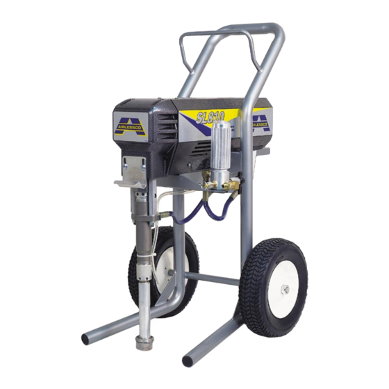
- Page 1 ® IRLESS AINT PRAYER ERVICE PERATION ANUAL AIRLESSCO - SL810 & 1100 ALLPRO - 910E & 1110E 001-493 FEB09...
-
Page 2: Table Of Contents
Replacement of Electrical Components ......26 28. Suction Assembly (55gal) ......... 22 Notes ................27 29. Electrical System............25 Airlessco Accessories ............. 30 30. Liquid Crystal Display..........26 Airlessco 5397 N. Commerce Ave, Moorpark, CA 93021 www.airlessco.com • (805) 523-0211... -
Page 3: Introduction
NOTE - Identifies essential procedures or extra information. All Service Procedures to be performed by an Authorized Airlessco Service Center ONLY. NO MODIFICATIONS or alterations of any AIRLESSCO Equipment or part is allowed. -
Page 4: Safety Warnings
WARNINGS NOTE TO PHYSICIAN: Injection in the skin is a traumatic MEDICAL ALERT - Airless Spray Wounds injury. It is important to treat the injury surgically as soon as If any fluid appears to penetrate your skin, get EMERGENCY possible. DO NOT DELAY treatment to research toxicity. Tox- MEDICAL CARE AT ONCE. - Page 5 WARNINGS - CONTINUED HOSES GROUNDING Tighten all fluid connections securely before each use. High Ground the sprayer and other components in the system pressure fluid can dislodge a loose coupling or allow high to reduce the risk of static sparking, fire or explosion which pressure spray to be emitted from the coupling and result in can result in serious bodily injury and property damage.
- Page 6 WARNINGS - CONTINUED AVOID COMPONENT RUPTURE PREVENT STATIC SPARKED FIRE/ EXPLOSIONS This sprayer operates at 3000 psi (205 bar). ALWAYS be ALWAYS be sure all equipment and objects being sprayed sure that all components and accessories have a maximum are properly grounded. working pressure of at least 3000 psi to avoid rupture ALWAYS ground sprayer, paint bucket and object being which can result in serious bodily injury including injection...
-
Page 7: Flushing
FLUSHING 1. NEW SPRAYER 5. STORAGE Your unit was factory tested in an oil solution which was left Oil-base paint: Flush with mineral spirits. in the pump. Before using oil-base paint, flush with mineral spirits only. Water-base paint: Flush with water, then mineral spirits and Before using water-base paint flush with mineral spirits, leave the pump, hose and gun filled with mineral spirits. -
Page 8: Setting Up
Fill the Packing Nut/Wet Cup with 5 drops of 5. FLUSH THE SPRAYER Airlessco Throat Seal Follow “Flushing Procedure” on page 5 of this manual. Oil (TSO). STARTING UP 1. LEARN THE FUNCTIONS OF THE (Prime/PR Valve) Used to relieve pressure CONTROLS. - Page 9 WARNING Be sure to relieve pressure in the pump after filling with 4. ADJUSTING THE PRESSURE Airlessco Pump Conditioner. a. Turn the Pressure Control Knob Clockwise to increase pressure and counterclockwise to decrease pressure. b. Always use the lowest pressure necessary to completely AVOIDING TIP CLOGS atomize the material.
-
Page 10: Pressure Relief Procedure
Airlessco Service Center. DAILY MAINTENANCE 1. Keep the displacement pump packing nut/wet cup lubricated with Airlessco TSO (Throat Seal Oil) at all times. The TSO helps protect the rod and the packings. 2. Inspect the packing nut daily. Your pump has a patented Triple Life Packing System. Packing life will be extended a minimum of three times if the following "Packing Adjustment"... -
Page 11: Airless Spray Gun Operation
AIRLESS SPRAY GUN OPERATION SPRAY FIG. 7 Attach spray gun to airless unit and tighten fittings securely. GUN SAFETY LATCH GUN SAFETY IN LOCKED POSITION LATCH Set the gun safety latch. (Also may be called gun safety lock, or trigger lock) * The gun safety latch should always be set when the gun is not being triggered. -
Page 12: Airless Spray Gun
AIRLESS SPRAY GUN FIG. 11 PARTS LIST FIGURE 11 Item No. Part No. Description 120-530* Gun Seat Assembly 120-535* Gasket-Seat 120-520* Needle Assembly 120-529 Gun Seat Adapter 120-562 Trigger Guard 120-539 Pivot Trigger Pin (008 Gun) 119-055 Bolt (Prolight Gun) 119-054 Nut (Prolight Gun) 120-509... -
Page 13: Airless Spray Troubleshooting
AIRLESS SPRAY TROUBLESHOOTING DEFECTS CAUSE CORRECTION Coarse spray Low pressure Increase the pressure Excessive fogging High pressure Reduce the pressure to satisfactory pattern distrabution (overspray) Material too thin Use less thinner Patten too wide Spray angle too large Use smaller spray angle tip Pattern too narrow Spray angle too small Use larger spray angle tip (if coverage is OK, try tip in same... -
Page 14: Spray Tip Selection Guide
TIP SELECTION GUIDE Spray tip selection is based on paint viscosity, paint type, & job needs. For light viscosities (thin paints), use a smaller tip; heavier (thicker paints), use a larger tip size. Spray tip size is based on how many gallons of paint per minute can be sprayed through the tip. -
Page 15: Regular Maintenance
2. Keep the displacement pump packing nut/wet cup 1/3 full of Airlessco Throat Seal Oil at all times. The TSO helps protect the packings and rod. 3. Lubricate Connecting Rod Pin every 3 months. -
Page 16: Field Troubleshooting
FIELD TROUBLESHOOTING PROBLEM CAUSE SOLUTION Unit doesn’t prime Airleak due to: •Loose suction nut • tighten suction nut • Worn o-rings • replace o-ring (106-018) on suction seat & o-ring (106-017) below suction seat Stuck or fouled balls • service inlet and outlet valves Prime/Pressure Relief valve •... -
Page 17: Servicing The Fluid Pump
SERVICING THE FLUID PUMP NOTE: CHECK EVERYTHING IN THE TROUBLESHOOTING CHART BEFORE DISASSEMBLING THE SPRAYER. FIG. 15 FLUID PUMP REINSTALL FLUID PUMP DISCONNECT 1. Loosen the packing nut & extend piston rod to fully up position. 1. Flush out the material you are Slip sleeve over the piston rod. -
Page 18: Servicing Inlet And Outlet Valves
SERVICING INLET NUT & OUTLET VALVE FIG. 20 INLET VALVE 1. Using the rod collar tool (189-211), unscrew the suction nut, containing suction seat support, off of the fluid body. 2. Remove the suction seat, O-ring, suction ball and suction ball guide with O-ring. 3. -
Page 19: Packing Replacement Procedures
PACKING REPLACEMENT PROCEDURES 11. Take the upper female gland & place on top of your DISASSEMBLY OF THE FLUID PUMP assembled upper packings with the inverted side 1. Unscrew & remove the packing nut. down. 2. Push the piston rod down through the packings & out of 12. -
Page 20: V-Packings
PACKING REPLACEMENT PROCEDURES FIG. 22 FIG. 23 PARTS LIST FIGURE 22 & 23 PARTS LIST FIGURE 22 & 23 Item No. Part No. Description Item No. Part No. Description 187-330-99 Piston Rod 187-059 Packing Leather 187-046 Packing Nut 187-037 Male Gland 187-313 Fluid Body 187-029... -
Page 21: Paint System
PAINT SYSTEM FIG. 24 PARTS LIST FIGURE 24 PARTS LIST FIGURE 24 Item No. Item No. Part No. Description Part No. Description 100-180 Prime Valve 100-109 Nipple (3/8”-1/4”) 301-348 Bypass Tube 169-013 Elbow 301-318-99 Pressure Control Assy (110V) 111-200 Manifold Filter 301-364-99 Pressure Control Assy (230V) 331-249-99 Sensor... -
Page 22: Complete Sprayer Assembly
COMPLETE SPRAYER FIG. 26 12,13 36, 37, 38, 39, 41... -
Page 23: Complete Sprayer Parts List
Suction Nut 140-035 Lock Washer (2) 187-001 Suction Fitting 140-051 Nut (2) 301-004 Suction Tube 301-134 Stopper (2) Replacement Label Kits Part No. Description 301-430 Airlessco SL810 301-435 Allpro 910E 301-431 Airlessco SL1100 301-436 Allpro 1110E 101-232 Decal, Center Stripe... -
Page 24: Suction Assembly 5 Gal
SUCTION ASSY - 5 GAL. - (301-090-99) FIG. 27 PARTS LIST FIGURE 27 Item No. Part No. Description FLUID PUMP 301-517-99 Suction Hose Assy (includes items 1-5) 141-008 Inlet Strainer 301-514 Suction Tube 301-516 Hose Clamps (2) 301-513A Hose 100-165 Elbow 188-377 Return Pipe... -
Page 25: Troubleshooting - Machine Does Not Start
If the motor is still hot to the touch, allow it to cool and then retest. If the motor is cool and there is not continuity on the red leads, contact Airlessco Technical Support to repair/replace the thermal coupler. Continuity shows that the motor's thermal coupler has not tripped. Proceed to step six. -
Page 26: Pressure Control Assembley Calibration
PRESSURE CONTOL ASS'Y CALIBRATION NOTE: ANYTIME A SENSOR OR PRESSURE CONTROL ASSEMBLY (BOARD) OR BOTH ARE REPLACED, THE FOLLOWING CALIBRATIONS MUST BE PERFORMED. NOTE: PRESSURE CONTROL ASSEMBLIES (BOARDS) ARE NOW BEING EQUIPPED WITH A GREEN GROUNDING WIRE ATTACHED. CONTECT THE GROUNDING WIRE TO TERMINAL BOX USING THE SAME SCREW THAT HOLDS THE GROUNDING WIRE FROM THE POWER CORD. -
Page 27: Electrical System
ELECTRICAL SYSTEM FIG. 29 BLACK GREEN & A2 A1 INHIBIT SWITCH S1 S2 LCD ZERO PRESSURE LCD SET ON-SL PHASE LIMIT P-ZR DISPLAY SENSOR ZERO PARTS LIST FIGURE 29 POWER YELLOW LIGHT LIGHT Item No. Part No. Description 331-168 Electrical Cord 110V 301-101 Electrical Cord 230V 331-185... -
Page 28: Replacement Of Electrical Components
REPLACEMENT OF ELECTRICAL COMPONENTS WARNING: ALWAYS UNPLUG THE ELECTRICAL CORD BEFORE SERVICING MACHINE! NOTE: ANYTIME THE PRESSURE CONTROL ASSEMBLY, SENSOR, OR BOTH ARE REPLACED, PERFORM THE CALIBRATIONS. PRESSURE CONTROL ASSEMBLY LIQUID CRYSTAL DISPLAY (LCD) (ELECTRICAL CONTROL BOARD) 1. Ensure that the power switch is OFF and that the machine is unplugged. -
Page 29: Notes
NOTES... - Page 30 NOTES...
- Page 31 NOTES...
-
Page 32: Airlessco Accessories
®...
Need help?
Do you have a question about the SL810 and is the answer not in the manual?
Questions and answers