Xerox 7750DXF - Phaser Color Laser Printer Service Manual
Phaser 7750 series
Hide thumbs
Also See for 7750DXF - Phaser Color Laser Printer:
- User manual (35 pages) ,
- Supplementary manual (5 pages) ,
- Manuallines (5 pages)
Table of Contents
Advertisement
Quick Links
Advertisement
Table of Contents
Troubleshooting

Related Manuals for Xerox 7750DXF - Phaser Color Laser Printer


Summary of Contents for Xerox 7750DXF - Phaser Color Laser Printer
- Page 1 7750 P h a s e r ® C o l o r L a s e r P r i n t e r Service Manual...
- Page 3 Phaser 7750 Color Laser Printer Service Manual Warning The following servicing instructions are for use by qualified service personnel only. To avoid personal injury, do not perform any servicing other than that contained in the operating instructions, unless you are qualified to do so.
- Page 4 Copyright © 2004, Xerox Corporation. All Rights Reserved. Unpublished rights reserved under the copyright laws of the United States. Contents of this publication may not be reproduced in any form without permission of Xerox Corporation. Copyright protection claimed includes all forms of matters of copyrightable materials and information now...
-
Page 5: Service Terms
Service Terms Manual Terms Various terms are used throughout this manual to either provide additional information on a specific topic or to warn of possible danger present during a procedure or action. Be aware of all symbols and terms when they are used, and always read NOTE, CAUTION, and WARNING statements. -
Page 6: Symbols Marked On The Product
Symbols Marked on the Product DANGER high voltage. Protective ground (earth) symbol. Hot surface on or in the printer. Use caution to avoid personal injury. The surface is hot while the printer is running. After turning off the power, wait 30 minutes. 30 min. -
Page 7: Power Safety Precautions
Power Safety Precautions Power Source For 110 VAC printers, do not apply more than 140 volts RMS between the supply conductors or between either supply conductor and ground. Use only the specified power cord and connector. For 220 VAC printers, do not apply more than 264 volts RMS between the supply conductors or between either supply conductor and ground. -
Page 8: Electrostatic Discharge (Esd) Precautions
Electrostatic Discharge (ESD) Precautions Some semiconductor components, and the respective sub-assemblies that contain them, are vulnerable to damage by Electrostatic discharge (ESD). These components include Integrated Circuits (ICs), Large-Scale Integrated circuits (LSIs), field-effect transistors and other semiconductor chip components. The following techniques will reduce the occurrence of component damage caused by static electricity. -
Page 9: Service Safety Summary
Service Safety Summary General Guidelines For qualified service personnel only: Refer also to the preceding Power Safety Precautions. Avoid servicing alone: Do not perform internal service or adjustment of this product unless another person capable of rendering first aid or resuscitation is present. Use care when servicing with power: Dangerous voltages may exist at several points in this product. -
Page 10: Servicing Electrical Components
Servicing Electrical Components Before starting any service procedure, switch off the printer power and unplug the power cord from the wall outlet. If you must service the printer with power applied, be aware of the potential for electrical shock. Warning Turning the power off by using the On/Off switch does not completely de- energize the printer. -
Page 11: Regulatory Specifications
The equipment described in this manual generates and uses radio frequency energy. If it is not installed properly in strict accordance with Xerox’ instructions, it may cause interference with radio and television reception or may not function properly due to interference from another device. -
Page 12: European Union
European Union Xerox Corporation declares, under our sole responsibility, that the printer to which this declaration relates is in conformity with the following standards and other normative documents: Following the provisions of the Low Voltage Directive 73/23/EEC and its amendments: EN 60950 (IEC 60950) "Safety of Information Technology Equipment including... - Page 13 @ 50 Hz This product, if used properly in accordance with the user’s instructions, is neither dangerous for the consumer nor for the environment. A signed copy of the Declaration of Conformity for this product can be obtained from Xerox. Service Manual...
- Page 14 Phaser 7750 Color Laser Printer...
-
Page 15: Table Of Contents
Contents Service Terms ..........iii Symbols Marked on the Product . - Page 16 #4 Skew (Rough) Setup....... 2-19 View the RegiCon Patterns......2-20 Sensors .
- Page 17 Engine Logic Board NVRAM Failure, Code 83 ....3-40 Controller to Engine Logic Board Time Failure, Code 84 ..3-40 Engine Logic Board Micro Pitch Failure, Code 85... . 3-40 High-Voltage Power Supply Failure, Code 86 .
- Page 18 Windows 98 and Windows Me Troubleshooting ... . 4-25 Macintosh Troubleshooting ......4-27 Novell NetWare Troubleshooting .
- Page 19 8 Service Parts Disassembly Overview ..........8-2 Standard Orientation of the Printer for Disassembly .
- Page 20 Part List 16.13 Left Cover Assembly (LTD) ....9-45 Part List 16.14 Tray 4/5 Lift Gear Assembly ....9-46 Part List 16.15 Electrical Components and Caster .
- Page 21 PL 17.5 Covers........11-48 PL 17.6 Top Cover and Eject Roll .
- Page 22 Phaser 7750 Printer...
-
Page 23: General Information
General Information In this chapter... Phaser 7750 Printer Configurations Parts of the Printer Phaser 7750 Front Panel Configuration Image Processor Board and Rear Panel Host Interface Routine Maintenance Items and Consumables Printer Specifications Chapter... -
Page 24: Printer Introduction And Overview
Printer Introduction and Overview The Xerox Phaser 7750 Color Laser Printer Service Manual is the primary document used for repairing, maintaining, and troubleshooting the printer. To ensure understanding of this product, complete the Xerox Phaser 7750 Printer Multi-Media Service Training and Self-Study Guide. -
Page 25: Phaser 7750 Printer Configurations
Phaser 7750 Printer Configurations A replaceable “Configuration Chip” holds configuration information that enables or disables built-in features as described below. Printer Configurations Features 7750B 7750DN 7750GX 7750DXF Processor and Clock Rate (Mhz) Max Print Speed (Letter/A4) 35/35 35/35 35/35 35/35 Maximum Memory (GB) Memory Configuration (MB) Resolutions (dpi) -
Page 26: Parts Of The Printer
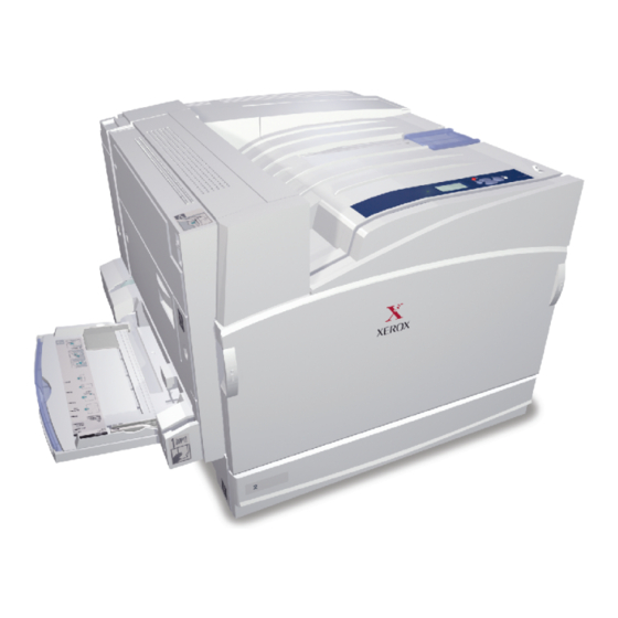
Parts of the Printer Exterior - Front View 7750-445 Face Down Tray Finisher Top Door H Release Front Door Finisher Output Tray Tray 1 (MPT) Finisher Door J 2500-Sheet High-Capacity Feeder Front Door right side release (release (1500-Sheet Lower Tray Deck not on left side not shown shown) Power Switch... -
Page 27: Exterior - Rear View
Exterior - Rear View 7750-446 USB Connection AC Power Cord Connection Ethernet 10/100 Base-T Connection Latch for Left Door A GFI Reset Button Tray 1 (MPT) in closed position General Information... -
Page 28: Phaser 7750 Front Panel Configuration
Phaser 7750 Front Panel Configuration The printer’s front panel consists of one LED, a display window, and six buttons. These buttons are used to navigate the menu system, perform functions, and select modes of operation for the printer. LED Indicators: Green = Ready to Print Flashing Green = Receiving, Processing Data, Printing or Power Saver Mode... -
Page 29: Image Processor Board And Rear Panel Host Interface
Image Processor Board and Rear Panel Host Interface The components on the image processor board are illustrated in the following figure. 7750-170 RAM (SODIMM) Processor Fan RAM (SODIMM) NVRAM USB Connector Ethernet Connector Health LEDs Hard Drive General Information... -
Page 30: Routine Maintenance Items And Consumables
Routine Maintenance Items and Consumables 7750-449 Routine Maintenance Items Consumables Transfer Roller Toner Cartridges Fuser Belt Cleaner Assembly Service Parts Imaging Units Accumulator Belt Waste Cartridge Consumable capacity is based on 5% per color on A4/Letter paper. Routine Maintenance Item capacity is based on A4 @ 5%. Routine Maintenance: Consumables: Transfer Roller... -
Page 31: Printer Specifications
Printer Specifications Physical Dimensions and Clearances Print Engine Dimensions Value Height: 493 mm (19.4 in.) Width: 644 mm (25.4 in.) Depth: 715 mm (28.15 in.) Weight: 91 kg (200 lbs.) 2500-Sheet High-Capacity Feeder Dimensions Value Height: 364 mm (14.3 in.) Width: 644 mm (25.4 in.) Depth:... -
Page 32: Mounting Surface Specification
Mounting Surface Specification These specifications apply to any Phaser 7750 printer used as a table-top printer, without a lower tray assembly or cart. There are 4 feet on the bottom of the printer. The right hand side of the printer is more susceptible to problems due to foot placement. - Page 33 The printer must not be tipped or tilted more than is shown in the following figure. 5mm Max 7750-341 Failure to adhere to these mounting specifications will void all guarantees of print quality and/or performance. Known problems that can occur as a result of exceeding the mounting surface specifications are: Color-to-Color mis-registration, primarily in the horizontal (laser scan) direction.
-
Page 34: Functional Specifications
Functional Specifications Characteristic Specification Printing process The Phaser 7750 printer uses lasers with an electrophotographic four-color (CMYK) single pass print process. Color medium Four color toner cartridges: Cyan, Yellow, Magenta, and Black EAHG Toner Resolution / Print Standard: 1200 x 600 dpi Modes OHP: 1200 x 600 dpi Enhanced: 1200 x 1200 dpi... -
Page 35: Environmental Specifications
Environmental Specifications Characteristic Specification Temperature: Operating: 10 to 32 Storage: -20 to 50 Humidity Normal operating: 10 to 85% relative humidity Optimum operating: 25 - 75% Altitude 0 to 2500 m (8000 ft.) Acoustic Noise Idle: 29 dB(A) Printing: 52 - 53 dB(A) Media and Tray Specifications For information on approved Phaser 7750 media and paper types, print the “Paper Tips Page”... - Page 36 1-14 Phaser 7750 Printer Service Manual...
-
Page 37: Theory Of Operation
Theory of Operation In this chapter... Summary of the Phaser 7750 Print Process Paper Path of the Printer EAHG Toner Technology Overview ROS and Regicon Technology Overview RegiCon Overview Sensors Chapter... -
Page 38: Summary Of The Phaser 7750 Print Process
Summary of the Phaser 7750 Print Process The Phaser 7750 Color Laser Printer is a ‘full-color laser printer’, that utilizes electrophotographic recording principles to place a full color image onto the print media. The system contains a drum and developing unit for each color (yellow, magenta, cyan and black (YMCK), and places the toner image of each color onto print media via an intermediate transfer belt, producing full-color prints. - Page 39 6. Secondary Transfer: The image on the accumulator belt is transferred onto the print media using the voltage supplied by the transfer roller. The conductive transfer roller receives a high positive voltage from the HVPS that puts it at a higher potential than the accumulator belt.
-
Page 40: Paper Path Of The Printer
Paper Path of the Printer The Phaser 7750 printer has a C-shaped paper-handling path. The design helps it achieve high production outputs. The paper paths available for the paper exiting the fuser are: Straight to the Output Tray in the Top Cover (facedown). Straight to the optional Finisher. -
Page 41: Paper Size Sensing
Paper Size Sensing Trays 2 through 5 automatically sense the standard size media loaded in the printer by using the paper size sensors mounted on the back inside of the printer. When paper is loaded in the tray and the paper guides are adjusted, the levers on the bottom of the trays change the size sensor actuator locations. - Page 42 Stack Height Sensing The pick roller feeds the paper to the paper path. As paper continues to feed, the stack height drops. When it reaches a certain level an actuator unblocks the stack height sensor. The control logic then stops paper feed and raises the paper tray. This causes the actuator flag to block the stack height sensor again which signals the control logic to resume feeding paper.
-
Page 43: Sided Printing
2-Sided Printing Inverter Forward Exit Roll Full Paper Inverter Reverse Clutch Stack Sensor Clutch Face Down Tray Fuser Exit Exit Gate Switch Fuser Assy Fuser Exit Roll FUSER ACCUMULATOR BELT Regi. Roll Regi. Clutch Registration Regi. Main Motor Sensor Duplex Motor 7750-450 Paper leaving the fuser can be directed to the top output tray or the finisher. -
Page 44: Fuser
Fuser The fuser receives its drive from the main motor. After the toner images are applied to the paper, the paper is then passed through the fuser. The fuser belt is pressed against the heat roller to melt the toner and bond it to the paper. The fuser belt is always spring loaded against the heat roller, but can be released for jam clearance. -
Page 45: Eahg Toner
EAHG Toner EA (Emulsion Aggreate High Gloss) toner is a relatively new type of toner with particles that are more spherical and uniform in size. This toner will be used for all Phaser 7750 Printer applications. The image below shows the EA toner particles. The small bumps are particles of additives that produce some of the characteristics of the new toner. -
Page 46: Technology Overview
Technology Overview Standby Power There are two types of standby power in this machine: switched AC and switched DC. Switched power requires that both the circuit breaker and the printer’s main power switch be in the ON position. Switched AC Power - This is the control signal whose power off transition is delayed to allow the second bias transfer roller to retract. -
Page 47: Drive Power
Drive Power The Drive Power subsystem includes five motors and their driven assemblies. Main Motor - The main motor provides the drive for paper feed, black developer housing, and the fuser. The main motor gets 24 VDC power from the +24 Volt power supply by way of the interface board. - Page 48 Imaging Unit Motors - There are two imaging unit motors providing drive to the four imaging units: one drives the Y, M, and C drums, and the other drives the K (black) drum. Like the main motor, the drum motors get 5 and 24 volt DC power from 5 and 24 volt power supplies via the interface board.
-
Page 49: System Power Supplies
System Power Supplies The System Power Supplies consist of: the T1, T2, and T3 HVPS, the 24 Volt LVPS, 3.3 VDC LVPS, and the (2) 5VDC LVPS. Engine Control Interface Board High Voltage Power Supply/ T1 Board High Voltage Power Supply/ T3 Board High Voltage Power Supply/ T2 Board AC Drive Board Noise Filter Board... - Page 50 24 V Low Voltage Power Supply 24 V Low Voltage Power Supply Fan AC Power Chassis 3.3 V Low Voltage Power Supply 5 V Low Voltage Power Supply 7750-448 2-14 Phaser 7750 Printer Service Manual...
-
Page 51: Ros And Regicon Technology Overview
ROS and Regicon Technology Overview The locations of the ROS and the ROS shutter solenoid are shown in the following figure. There are four ROS shutters (not shown). The ROS module is field replaceable and contains four laser diodes, one polygon motor/mirror, and several lenses and mirrors. - Page 52 In the Write Black process for the Phaser 7750 printer, the four individual images, one in each color, are transferred to the surface of the accumulator belt.The second transfer roller puts a positive charge on the copy paper. Then the four-color image is transferred to the sheet of paper in one pass.
-
Page 53: Regicon Overview
RegiCon Overview The RegiCon procedure is used to ensure that the four lasers in the ROS are correctly aligned to provide correct registration for each color. The Mark On Belt (MOB) sensors are used in this procedure to determine the relative position of chevrons developed onto the accumulator belt. - Page 54 The chevron patterns used for the RegiCon setup are shown in the following figure. The components of the RegiCon adjustment include: Skew (Fine) Setup (Pattern 1) IN/OUT Setup (Pattern 1) Center Setup (Pattern 1) Coarse Skew Setup (Pattern 2) 2-18 Phaser 7750 Printer Service Manual...
-
Page 55: Skew (Fine) Setup
#1 Skew (Fine) Setup The Skew (Fine) Setup is performed to ensure that images on the accumulator belt are not skewed. To complete this part of the procedure, a series of chevron images are developed on the belt, using all four colors. (Pattern 1 on the previous figure shows the chevron patterns). -
Page 56: View The Regicon Patterns
View the RegiCon Patterns It is possible to see the patterns that are developed on the accumulator belt for the RegiCon calibration by performing the following steps: If there is a finisher present on the machine, slide it to the right so that the right hand access door to the accumulator belt can be opened. - Page 57 Reinsert the accumulator belt assembly into the Phaser 7750 printer without the Stand Plate. The area that was covered by the Stand Plate will be the area in which you see the images on the accumulator belt. With the right hand door interlock activated, turn the printer on. Note For machines with finishers, unplug the finisher from the Phaser 7750 printer prior to powering up.
-
Page 58: Sensors
Sensors Looking at the imaging path illustration below, note that there are two kinds of sensors that play an important role in the control of image quality for the printer. Output Fuser Internal I/P Board Toner Test Cartridge Patterns Transfer Sensor Roller Transfer... - Page 59 Environment Accumulator Belt Sensor Edge Sensor Automatic Density Accumulator Belt Control Sensor Home Sensor Automatic Toner Concentration Sensor Duplex K, C, M, Y Wait Sensor Tray 1 Paper Size Sensor Mark On Belt Sensor Waste Cartridge Full Sensor 7750-461 Theory of Operation 2-23...
-
Page 60: Atc Sensors
ATC Sensors The ATC sensor is a part of the developer housing. It provides an indication of the concentration of toner relative to the carrier beads contained in the developer housing. Generally speaking, higher concentrations of toner are more easily developed, because they have less triboelectric bond to the carrier beads. -
Page 61: Adc Sensor
There is a developer problem either with the housing or the amount of beads in the developer. Tone Up/Down Messages Front Panel Message Typical Values [CMYK] Sens Warn Pages = XX Number of pages since last check ATC Control = XXX ATC Corr = XXX 604-606 Ave ATC = XXX... -
Page 62: Adc Output Check
Determine toner cartridge empty (triggered by ATC sensor). 2 patches per color are printed and ADC control is initiated at: Power-on, return from E , after interlock close. NERGY End of each job. Within a job (every 80 pages at full speed, every 40 pages at half speed. - Page 63 If the ADC Shutter Fail test detects a problem, check the connector and the shutter for a binding or out of position condition. If these actions do not resolve the problem, replace the MOB Assembly. If the following values all equal none, the test has detected no problems LD Illum Warn = None ADC Patch Fail = None VBCR Warn = None...
-
Page 64: Lower Tray Feeders Sensor And Board Locations
Lower Tray Feeders Sensor and Board Locations LTD Board (3T) HCF Board (TT) 7750-459 2-28 Phaser 7750 Printer Service Manual... - Page 65 Paper-Size Switch Assembly -Tray 3 Tray 5 Take-Away Sensor -Tray 4 Tray 4 Take-Away Sensor -Tray 5 Take-Away Sensor Paper-Size Switch Assembly -Tray 3 No-Paper Sensor/Level Sensor Paper-Size Switch Assembly Tray 3 Tray 4 -Tray 4 -Tray 5 Tray 5 Tray 4 Take-Away Sensor Tray 5 Take-Away Sensor 7750-462...
- Page 66 Left hand cover interlock switch actuator Paper feed sensor actuator tray 4 Paper detect One way sensor actuator clutch tray 3 tray 3 tray 4 tray 4 tray 5 tray 5 Friction clutch Paper feed tray 3 sensor actuator tray 5 tray 4 tray 5 Friction...
-
Page 67: Error Messages And Codes
Error Messages and Codes In this chapter... Introduction Overview for Troubleshooting Error Codes System Startup and POST Error Messages and Codes Index Table Error Messages and Codes Procedures Chapter... -
Page 68: Introduction
Introduction This section covers troubleshooting procedures for the Phaser 7750 printer front panel error messages and codes. Only jams and fatal errors will produce an associated numeric code. Error messages and codes are generally specific, making it important that service personnel and users record errors when reporting problems with the printer. -
Page 69: Service Checklist
Service Checklist This checklist is an overview of the path a service technician should take to service the Phaser 7750 printer and it’s options. Step 1: Identify the Problem: Verify the problem reported by the customer. Check for any error codes and write them down. If the printer is capable of printing, print normal customer prints and service test prints to: Make note of any print-quality problems in the test prints. -
Page 70: Service Rip (Every Call) Procedures
Service RIP (Every Call) Procedures These procedures are to be used for every service call. Print an error log then diagnose and repair any problems as indicated. Print a “Usage Profile” report, then diagnose and repair any problems as indicated. Check the cleanliness of the interior and exterior of the printer including fans. -
Page 71: Overview For Troubleshooting Error Codes
Overview for Troubleshooting Error Codes Definition of the Chain-Link Codes A chain-link is a numeric code represented as a pair with the chain first and the link second. The “chain” is a 2-digit identifier representing a major or higher level sub- assembly. - Page 72 General Notes on Troubleshooting Unless indicated otherwise, the instruction “turn ON printer power” means for you to switch ON the printer power and let the printer proceed through POST to a ‘Ready’ condition. When instructed to take resistance readings between “P/J 232 <=> P/J 210” (without specified pin numbers), check all pins.
-
Page 73: System Startup And Post
System Startup and POST System Boot Sequence When the main power switch is turned on, the ‘health’ LED on the image processor board turns on immediately. The boot loader checks for RAM present and functional. If not, it posts a very large “RAM ERROR”... -
Page 74: Post Faults
If any tests fail, the front panel screen freezes with the name of the test displayed and the line posted is “Call Customer Service”. After the POST tests have finished running, the Xerox ‘splash screen’ is posted to the front panel and PostScript begins initialization. -
Page 75: Post Diagnostic Test Descriptions
POST Diagnostic Test Descriptions Fault Fault Test Type Code Description This test fails if the boot loader finds no RAM present or faulty RAM. SDRAM Hard Boot loader posts the message “RAM error” to the front panel and blinks the front panel LED and IP Board health LED. -
Page 76: Error Messages And Codes Index Table
Error Messages and Codes Index Table Code Error Message Chain-Link Page Laser Unit Failure 06-380 pg. 3-12 06-381 06-382 06-383 06-385 Laser Unit Polygon Motor Failure 06-372 pg. 3-12 Yellow ATC Sensor Failure 09-380 pg. 3-13 Magenta ATC Sensor Failure 09-381 pg. - Page 77 Code Error Message Chain-Link Page Black Imaging Unit Motor Failure 04-363 pg. 3-37 Waste Cartridge Full Detection Sensor Failure 09-358 pg. 3-38 Engine Logic Board Failure 04-341 pg. 3-39 04-343 Controller To Engine Communication Failure 04-358 pg. 3-39 Engine Logic Board RAM/ROM Failure 04-340 pg.
-
Page 78: Error Messages And Codes Procedures
Error Messages and Codes Procedures Laser Unit Failure, Code 10 Laser Unit Polygon Motor Failure, Code 11 Note If this failure reoccurs three times successively, an Engine NVRAM value is set preventing further printer use until the Clear Tech Rep Fault (see pg. 6-20) is performed. - Page 79 Yellow ATC Sensor Failure, Code 12 Magenta ATC Sensor Failure, Code 13 Cyan ATC Sensor Failure, Code 14 The ATC Sensor detects an insufficient amount of developer. Note If this failure reoccurs three times successively, an Engine NVRAM value is set preventing further printer use until the Clear Tech Rep Fault (see pg.
- Page 80 Troubleshooting Procedure (Continued) Step Actions and Questions Measure the voltage at... Replace the Go to step 7. Yellow = P405B2 engine control Magenta = P405B9 board. Cyan = P405A9 on the engine control board. Is the voltage 0 VDC? Remove the Imaging Unit Plate cover. Replace the wiring Replace the ATC harness.
-
Page 81: Black Atc Sensor Failure, Code 15
Black ATC Sensor Failure, Code 15 The ATC Sensor detects an insufficient amount of developer. Note If this failure reoccurs three times successively, an Engine NVRAM value is set preventing further printer use until the Clear Tech Rep Fault (see pg. 6-20) is performed. - Page 82 Troubleshooting Procedure (Continued) Step Actions and Questions Remove the imaging unit plate cover. Replace the wiring Replace the ATC harness. sensor. Inspect the wiring harness between the engine control board and the developer housing assembly. Is the wiring harness defective? Run approximately 10 pages of the solid fill full-page prints for this color to ensure the error is cleared.
-
Page 83: Transfer Roller Contact Failure, Code 20
Transfer Roller Contact Failure, Code 20 Transfer Roller Retract Failure, Code 21 The Transfer Roller did not meet the contact position, or the Transfer Roller did not reach the retract position. Troubleshooting References Applicable Parts Wiring and Plug/Jack Map References Left Door Retract Home Sensor Engine Control Board... -
Page 84: 1St Btr Contact Or Retract Failure
1st BTR Contact or Retract Failure Troubleshooting References Applicable Parts Wiring and Plug/Jack Map References Retract Sensor and Harness Accumulator Belt Assembly Troubleshooting Procedure Step Actions and Questions Is the retract sensor or actuator damaged Repair or reseat Go to step 2. or out of position? the sensor. -
Page 85: Accumulator Belt Home Position Took Too Long, Code
Accumulator Belt Home Position Took Too Long, Code 30 Accumulator Belt Home Position Failure, Code 31 The accumulator belt home sensor did not detect the belt home signal. Note If this failure reoccurs three times successively, an Engine NVRAM value is set preventing further printer use until the Clear Tech Rep Fault (see pg. - Page 86 Troubleshooting Procedure (Continued) Step Actions and Questions Enter service diagnostics and run the Go to step 3. Go to step 6. Clear Tech Rep Fault (see pg. 6-20) 04-346 procedure. Enter the Adjustments/Calibrations menu and run the Belt Edge Learn Test with the right hand door open and the door interlock held actuated.
- Page 87 Troubleshooting Procedure (Continued) Step Actions and Questions Using a Type II Toner Vacuum, vacuum Replace the belt Go to step 9. out the belt cleaner and waste auger. cleaner assembly. Is the actuating lever broken off of the belt cleaner toner gate? Remove the waste toner cartridge.
-
Page 88: Accumulator Belt Edge Sensor Failure, Code 32
Accumulator Belt Edge Sensor Failure, Code 32 Accumulator Belt Drive Logic Failure, Code 34 Troubleshooting References Applicable Parts Wiring and Plug/Jack Map References Accumulator Belt Assembly Engine Interface Board Engine Control Board Caution If the Accumulator Belt is damaged, determine the cause of the damage before installing a new assembly. - Page 89 Troubleshooting Procedure (Continued) Step Actions and Questions Measure the voltage between the Go to step 7. Replace in the engine control interface board and following order: J533A-9 and frame ground. engine control interface board Does the voltage measure +5 VDC? engine control board Measure the voltage between the...
-
Page 90: Unexpected Accumulator Belt Home Sensor Signal, Code 33
Unexpected Accumulator Belt Home Sensor Signal, Code 33 Troubleshooting References Applicable Parts Wiring and Plug/Jack Map References Accumulator Belt Assembly Engine Control Interface Board Engine Control Board Caution If the Accumulator Belt is damaged, determine the cause of the damage before installing a new assembly. -
Page 91: Fuser Main Lamp Failure, Code 35
Fuser Main Lamp Failure, Code 35 The lamp control circuit has failed resulting in the front thermistor detecting an overheat condition. Note If this failure reoccurs three times successively, an Engine NVRAM value is set preventing further printer use until the Clear Tech Rep Fault (see pg. 6-20) is performed. -
Page 92: Install Or Reseat Fuser, Code 41
Install or Reseat Fuser, Code 41 Front thermistor open error. This is a cold condition. Note If this failure reoccurs three times successively, an Engine NVRAM value is set preventing further printer use until the Clear Tech Rep Fault (see pg. 6-20) is performed. -
Page 93: Fuser Sts (Front) Warm Time Failure, Code 42
Fuser STS (Front) Warm Time Failure, Code 42 Main heater warm-up error. The temperature did not reach the “Ready” temperature within the specified time. Fuser SSR1 On Time Failure, Code 43 The main heater remained ON for more than the specified time. Troubleshooting References Applicable Parts Wiring and Plug/Jack Map References... - Page 94 Troubleshooting Procedure (Continued) Step Actions and Questions Is the line voltage present at FS41 on the Go to step 6. Go to step 7. AC Drive Board? Check the wiring harness between Replace the fuser Replace the AC FS41 and J600-1 for an open circuit or assembly.
-
Page 95: Fuser Sub Lamp Overheat Failure, Code 44
Fuser Sub Lamp Overheat Failure, Code 44 The front thermistor has detected an overheat condition. Note If this failure reoccurs three times successively, an Engine NVRAM value is set preventing further printer use until the Clear Tech Rep Fault (see pg. 6-20) is performed. -
Page 96: Fuser Sts (Rear) Failure, Code 45
Fuser STS (Rear) Failure, Code 45 Rear Thermistor open error. The machine logic detected an open circuit in the rear thermistor. Troubleshooting References Applicable Parts Wiring and Plug/Jack Map References Fuser Engine Control Board Troubleshooting Procedure Step Actions and Questions Turn OFF power, remove the fuser Go to step 2. -
Page 97: Fuser Sts (Rear) Warm Time Failure, Code 46
Fuser STS (Rear) Warm Time Failure, Code 46 Sub-heater warm-up error. The temperature did not reach “Ready” temperature within the specified time. Fuser SSR2 On Time Failure, Code 47 The Sub-heater remained ON for more than the specified time. Troubleshooting References Applicable Parts Wiring and Plug/Jack Map References Fuser... - Page 98 Troubleshooting Procedure (Continued) Step Actions and Questions Is line voltage present at FS47 on the Go to step 6. Go to step 7. AC drive board? Check the wiring harness between Replace the fuser Replace the AC FS47 and J600-1 for an open circuit or assembly.
-
Page 99: Fan Failure, Code 48
Fan Failure, Code 48 The machine logic detected a failure of the Fuser fan, LVPS fan, or rear fan. Troubleshooting References Applicable Parts Wiring and Plug/Jack Map References Fuser Fan LVPS Fan Rear Fan Troubleshooting Procedure Step Actions and Questions Enter service diagnostics and run the Go to step 4. - Page 100 Troubleshooting Procedure (Continued) Step Actions and Questions Does the front panel indicate the fans are Replace the rear Check the wiring fan. tot he rear fan, if the wiring is OK, replace the engine control board. Does the LVPS fan revolve at high speed? The fans are Go to step 8.
-
Page 101: Imaging Unit Motor Failure, Code 60
Imaging Unit Motor Failure, Code 60 Troubleshooting References Applicable Parts Wiring and Plug/Jack Map References Imaging Unit Drive Motor Engine Control Board Troubleshooting Procedure Step Actions and Questions Enter service diagnostics and run the Go to step 7. Go to step 2. Imaging Unit Motor test. -
Page 102: Imaging Unit [1] [2] [3] [4] Communications Failure, Code 70, 71, 72, 73
Imaging Unit [1] [2] [3] [4] Communications Failure, Code 70, 71, 72, 73 Troubleshooting References Applicable Parts Wiring and Plug/Jack Map References Imaging Unit Imaging Unit Plate Assembly Troubleshooting Procedure Step Actions and Questions Replace the imaging unit reporting the Go to step 2. -
Page 103: Black Imaging Unit Motor Failure
Black Imaging Unit Motor Failure Troubleshooting References Applicable Parts Wiring and Plug/Jack Map References Imaging Unit Motor Engine Control Interface Board Engine Control Board Troubleshooting Procedure Step Actions and Questions Run the Black Imaging Unit Motor test from Go to step 7. Go to step 2. -
Page 104: Waste Cartridge Full Detection Sensor Failure, Code 78
Waste Cartridge Full Detection Sensor Failure, Code 78 Troubleshooting References Applicable Parts Wiring and Plug/Jack Map References Waste Cartridge Waste Cartridge Full Sensor Engine Control Board Troubleshooting Procedure Step Actions and Questions Remove the waste cartridge sensor Go to step 5. Go to step 2. -
Page 105: Engine Logic Board Failure, Code 80
Engine Logic Board Failure, Code 80 Troubleshooting Procedure Step Actions and Questions Cycle power to the printer to clear the Complete Replace the error. engine control board or the Did this clear the error? image processor board. Controller to Engine Communications Failure, Code 81 Troubleshooting Procedure Step Actions and Questions... -
Page 106: Engine Logic Board Nvram Failure, Code 83
Engine Logic Board NVRAM Failure, Code 83 Troubleshooting Procedure Step Actions and Questions Cycle power to the printer to clear the Complete. Replace in the error. following order: Did this clear the error? engine control board image processor board Controller to Engine Logic Board Time Failure, Code 84 Troubleshooting Procedure Step Actions and Questions... -
Page 107: Tray Lift Failure, Code 87
Tray Lift Failure, Code 87 The tray level sensor does not detect that the tray has lifted. Examine the trays and paper feed assemblies for any physical damage before starting the troubleshooting procedure. Troubleshooting References Applicable Parts Wiring and Plug/Jack Map References Tray Level Sensor Paper Select Switch Assembly Paper Feed Motor... - Page 108 Troubleshooting Procedure Step Actions and Questions Reseat the paper tray. Replace the paper Replace in order feed motor. until resolved: Does SW1-4: indicate H in any position? paper-select switch assembly engine interface board engine control board Pull out and then reseat the problem Go to step 8.
-
Page 109: Tray 1/Mpt Size Sensor (7-274), Code
Tray 1/MPT Size Sensor (7-274), Code? An open circuit has been detected in the Paper Size Senor Troubleshooting References Applicable Parts Wiring and Plug/Jack Map References Tray 1/MPT Assembly Engine Control Interface Board. Engine Control Board Troubleshooting Procedure Step Actions and Questions Is J610-2 between +0.15 and +3.1 VDC? Go to step 2. -
Page 110: Lower Tray Communication Failure, Code 88
Lower Tray Communication Failure, Code 88 Troubleshooting References Applicable Parts Wiring and Plug/Jack Map References Engine Control Interface Board Tray module board Engine Control board Troubleshooting Procedure Step Actions and Questions Is J668-1 on the tray module board Go to step 2. Use the wirenets +5 VDC? to troubleshoot... -
Page 111: Reflective Sensor Procedure
Reflective Sensor Procedure Troubleshooting References Applicable Parts Wiring and Plug/Jack Map References Reflective Sensor Engine Control Board Refer to the figure below during this procedure.. DOUBLE PLUG SENSOR DC ROM DC ROM J121 +5VDC +5VDC CONTROL LOGIC 7750-343 Troubleshooting Procedure Step Actions and Questions Enter service diagnostics and run the... -
Page 112: Transmissive Sensor Procedure
Transmissive Sensor Procedure Troubleshooting References Applicable Parts Wiring and Plug/Jack Map References Transmissive Sensor Engine Control Board Refer to the following figure during this procedure. DOUBLE PLUG SENSOR DC ROM DC ROM +5VDC +5VDC CONTROL LOGIC 7750-342 Troubleshooting Procedure Step Actions and Questions Enter service diagnostics and run the Replace the... -
Page 113: Finisher Stapler Move Sensor On Failure, Code 111
Finisher Stapler Move Sensor On Failure, Code 111 Finisher Stapler Move Sensor Off Failure, Code 112 Error Code 111: The staple move sensor did not turn ON within 2 seconds after the system has started to move to the staple position and the staple move sensor has turned off. - Page 114 Troubleshooting Procedure (Continued) Step Actions and Questions Is +24 VDC present at P847-4? Replace the Troubleshoot the finisher control +24 VDC board. interlock circuit, using the "Troubleshooting the 24 VDC LVPS" on page 4-18. 3-48 Phaser 7750 Printer Service Manual...
-
Page 115: Finisher Stapler Failure, Code 113
Finisher Stapler Failure, Code 113 The staple home sensor doesn’t turn ON within 2 seconds after the stapler motor started to turn backwards. Troubleshooting References Applicable Parts Wiring and Plug/Jack Map References Finisher Control Board Staple Unit Assembly Troubleshooting Procedure Step Actions and Questions Enter service diagnostics. - Page 116 Troubleshooting Procedure (Continued) Step Actions and Questions With the Stapler Close Motor test running Replace in the Troubleshoot and is +24 VDC present at J847-7? following order: repair the +24 VDC stapler head assembly interlock circuit. finisher control board 3-50 Phaser 7750 Printer Service Manual...
-
Page 117: Front Tamper Home Sensor Failure, Code 114
Front Tamper Home Sensor Failure, Code 114 With the Front Tamper Home Sensor OFF the Front Tamper Home Sensor did not turn ON within 800 ms after the move to the Front Tamper Home position has begun. With the Front Tamper Home Sensor on the Front Tamper Sensor did not turn Off when the Front Tamper Home Sensor is deactuated. -
Page 118: Rear Tamper Home Sensor Failure, Code 115
Rear Tamper Home Sensor Failure, Code 115 With the Rear Tamper Home Sensor OFF the Rear Tamper Home Sensor did not turn On within 800 ms after the move to the Rear Tamper Home position has begun. With the Rear Tamper Home Sensor on the Rear Tamper Sensor did not turn Off when the Rear Tamper Home Sensor is deactuated. -
Page 119: Finisher Stacker Height Sensor Off Failure, Code 116
Finisher Stacker Height Sensor Off Failure, Code 116 The Stack Height Sensor did not detect that the tray went down within 5 seconds after the Stacker Tray had been signaled to lower down at initialization. Or, the Stack Height Sensor did not detect the tray moving up within 5 seconds after the Stacker Tray had been signaled to lift. - Page 120 Troubleshooting Procedure Step Actions and Questions Is +24 VDC present at P/J 847-11 with the Replace the Replace the Finisher Stacker Motor Down test running in stacker motor. finisher control diagnostics? board. 3-54 Phaser 7750 Printer Service Manual...
-
Page 121: Finisher Stacker Tray Failure, Code 117
Finisher Stacker Tray Failure, Code 117 The system detected that the Stacker Tray Upper Limit Sensor was turned ON after the Stacker Tray began lifting up. Or the Stacker Tray Upper Limit Sensor remained on after the lowering down of the Stacker Tray was completed. Troubleshooting References Applicable Parts Wiring and Plug/Jack Map References... - Page 122 Troubleshooting Procedure (Continued) Step Actions and Questions Is +24 VDC present at P/J 847-11 with the Replace the Replace the Finisher Stacker Motor Down test running in stacker motor. finisher control diagnostics? board. 3-56 Phaser 7750 Printer Service Manual...
-
Page 123: Finisher Stapler Front Corner On Failure, Code 118
Finisher Stapler Front Corner On Failure, Code 118 Finisher Stapler Front Corner Off Failure, Code 119 Error Code 118: The Staple Front Corner Sensor did not turn ON within 2 seconds after the system started to move to the Front Corner. Or the Staple Front Corner Sensor remained ON when starting the move to the Front Corner. -
Page 124: Finisher Eject Clamp Home Sensor On Failure, Code
Finisher Eject Clamp Home Sensor On Failure, Code 120 Finisher Eject Clamp Home Sensor Off Failure, Code 121 Error Code 120: The Eject Clamp Home Sensor did not turn ON within 5 seconds after the Eject Clamp Up was started. Error Code 121: The Eject Clamp Home Sensor did not turn OFF within 2 seconds after the Eject Clamp Down was started. -
Page 125: Finisher Decurler Failure, Code 122
Finisher Decurler Failure, Code 122 The level of the Decurler Cam Home Sensor did not change 4 seconds after the Decurler Cam Clutch has turned on. Troubleshooting References Applicable Parts Wiring and Plug/Jack Map References Decurler Cam Clutch Stacker Motor Finisher Control Board Troubleshooting Procedure Step... -
Page 126: Finisher Set Clamp Failure, Code 123
Finisher Set Clamp Failure, Code 123 The set clamp home sensor did not turn on within 2 seconds after the set clamp started operation. Troubleshooting References Applicable Parts Wiring and Plug/Jack Map References Set Clamp Solenoid Finisher Control Board Troubleshooting Procedure Step Actions and Questions Check the Set Clamp home sensor in... -
Page 127: Finisher Communication Failure, Code 124
Finisher Communication Failure, Code 124 There are no diagnostic routines for problems involving serial communications. It is recommended that you address the following assemblies in this order: Finisher Control Board Engine Control Board Perform continuity checks on any wiring harnesses involved. Finisher Staple Mode Logic Failure, Code 125 There are no diagnostic routines for problems involving serial communications. - Page 128 3-62 Phaser 7750 Printer Service Manual...
-
Page 129: General Troubleshooting
General Troubleshooting In this chapter... Introduction Service Diagnostics Front Panel Troubleshooting Inoperable Printer Troubleshooting Troubleshooting Power Supplies and Interlocks Media Jams and the Paper Path Operating System and Application Problems Chapter... -
Page 130: Introduction
Introduction This chapter covers the general startup, PostScript, and power supply operations of the printer to aid in troubleshooting problems not associated with an error code or front panel error message. For troubleshooting problems associated with an error code or front panel error message, see "Error Messages and Codes"... -
Page 131: Service Diagnostic Front Panel Button Descriptions
Service Diagnostic Front Panel Button Descriptions Button Function BACK Returns to the prior higher level menu structure, if available. If help text is displayed on the front panel, pressing BACK restores the current menu item and remove the help text. CANCEL Terminates the current test. - Page 132 Test Front Panel Display Test Operation Definition Jam Info No Static Jam Detected Location of Jam <Press Back or Cancel to exit.> Static Jam: area name Fault History <nnn> text: mmm <nnn>: is a service defined numeric code, see "Service Usage Profile Status Codes"...
- Page 133 Test Front Panel Display Test Operation Definition Print Laser Check Fuser warming up This is a quick test for all four laser Laser Init colors, including developer and Startup | Imaging | Delivering | toner. Finishing All four primaries are present on Laser Done the page.
- Page 134 Test Front Panel Display Test Operation Definition Jam Sensors LH Low Cover Area is L H = Paper present LH Cover Area is L L = Paper not present LH Fuser Area is L Duplex Cover Area is L Tray Left Cover Area is L Tray #3 Area is L Tray #4 Area is L Tray #5 Area is L...
- Page 135 Test Front Panel Display Test Operation Definition BTR Sensors BTR Y is L H = Error BTR M is L L = No error BTR C is L BTR K is L 1st BTR is L 2nd BTR is L ADC Sensor ADC is XXX ADC = Automatic Density...
- Page 136 Test Front Panel Display Test Operation Definition Finisher Sensors Interlocks Optional - only if Finisher is Left-Hand Cover is L installed Top Cover is L Docking is H Horiz. Transport is L H = Open, actuated or paper Horizontal Transport present Entry is L L = Closed, deactuated or no paper...
- Page 137 Test Front Panel Display Test Operation Definition Steering Motor Do you wish to continue? CAUTION To avoid damaging the Accumulator Belt, it is recommended that you leave the belt installed and perform the Belt Motor On Edge Learn test instead, See "Belt Edge Motor Off Learn"...
- Page 138 Test Front Panel Display Test Operation Definition Offset Motor Direction: Forward Press Up/Down to change setting. Backward Color Developer Developer Motor is On Motor Turn Motor Off Developer Motor All Motors Off Dispensor Motor Disp. Motor: Yellow NOTE Only run this test once per power cycle to avoid Magenta excessive toner being...
- Page 139 Test Front Panel Display Test Operation Definition Clutch Tests Tests functionality of clutches by activating one clutch at a time. Take-Away Clutch Clutch On Clutch Off Developer Clutch Clutch On Clutch Off All tests are activated by pressing Registration Clutch Clutch On Listen for the clutch.
- Page 140 Test Front Panel Display Test Operation Definition ADC Output Check Measuring: This tests the Automatic Density Result = 0 Correction sensor. Stop Status = 0 ADC Sensor Fail = 0 ADC shutter Fail - 0 Tone Up/Down Measuring: This tests the Automatic Toner Result = 0 Status = 0 Calibration sensor.
- Page 141 Test Front Panel Display Test Operation Definition Store Engine NVRAM **Writes data to HD** This takes data from engine Are you sure? NVRAM and stores it onto the drive. See "Store Engine NVRAM" on page 6-21. Exit Exits to PostScript without running POST. General Troubleshooting 4-13...
-
Page 142: Front Panel Troubleshooting
Replace the internal hard drive (see page 8-39). Replace the image processor board (see page 8-38). Front Panel Continually Displays “Xerox Phaser 7750” Splash Screen Enter service diagnostics mode and watch the front panel during the "initializing" period for messages indicating any printer faults. -
Page 143: Inoperable Printer Troubleshooting
Front Panel Displays "Fatal Fault Encountered" Message See the procedure for "Controller to Engine Communications Failure, Code 81" on page 3-39. Inoperable Printer Troubleshooting False LH Door, RH Door, Front Door Open, or Imaging Units Missing Messages See the "Troubleshooting Power Supplies and Interlocks" on page 4-16. For all of the Following Problems go to the Error Code Procedure "Tray Lift Failure, Code 87"... -
Page 144: Troubleshooting Power Supplies And Interlocks
Troubleshooting Power Supplies and Interlocks Troubleshooting AC Power Note The GFI, Noise Filter, and AC Drive Board are all part of the AC Electrical Chassis. Actions Check the AC input voltage at the outlet. Reconnect AC power. If the GFI trips immediately with the power switch OFF, disconnect AC power, remove the rear cover and metal shields. -
Page 145: Troubleshooting The Low-Voltage Power Supplies
Troubleshooting the Low-Voltage Power Supplies 3.3 VDC, 5 VDC and 24 VDC voltages are supplied by individual low-voltage power supply boards. The 24 VDC LVPS requires the presence of a 5 VDC enabling signal to operate. Note Before troubleshooting power supply problems, disconnect the lower tray deck or finisher, if installed, and restart the printer. -
Page 146: Troubleshooting The +3.3 Vdc And (2) +5 Vdc Low-Voltage Power Supplies
Troubleshooting the +3.3 VDC and (2) +5 VDC Low- Voltage Power Supplies Note Switch off power and disconnect the power cord. Actions Remove the rear cover and rear shield. Disconnect the harnesses to connectors P505, P510, P511 and 2nd BTR on the T1 HVPS, remove 3 screws and lower the T1 HVPS. -
Page 147: Interlock Circuit Diagram
Interlock Circuit Diagram PRINT CARTRIDGE CRUM CONNECTORS J631 P536 INTERFACE LVPS BOARD WASTE CARTRIDGE P537 INTLK SW LVPS POWER RELAY FRONT COVER INTLK SW R/H COVER INTLK SW LH COVER INTLK SW S7700-432 The +24 VDC Interlock Circuit The 24 VDC interlock circuit runs from the 24 VDC LVPS to the L/H door interlock switch, the R/H door interlock switch, and the front door interlock switch back to the engine control interface board, then into the engine control board. - Page 148 The +5 VDC Interlock Circuit The 5 VDC interlock circuit runs from the 5 VDC LVPS to the L/H door switch, then to the engine control interface board, out to the R/H door switch, back to the engine control interface board, out to the front door, through the coil of the LD power relay and back to the 5 VDC LVPS.
-
Page 149: Media Jams And The Paper Path
Media Jams and the Paper Path Media-Based Problems Print the Paper Tips page from the printer’s front panel for a list of the supported media types and weights. The customer should be using a quality laser printer paper. The printer may have trouble picking smooth-finish paper. - Page 150 Feed paper through the printer from each of the available trays, including Tray 1/MPT. Is the paper damaged when fed out of one tray but not when fed out of the others? If so, inspect the tray for damage, ensure that the media guides are set correctly and verify that the proper media is being used.
-
Page 151: Operating System And Application Problems
Operating System and Application Problems Windows 2000, Windows XP, Windows Server 2003 Troubleshooting (TCP/IP) Note For Windows XP, select Classic Look or the Windows XP procedures will not match the steps below. To select Classic Look, click Start, then Settings, then Taskbar and Start Menu. -
Page 152: Windows Nt 4.X Troubleshooting (Tcp/Ip)
Click Print Test Page. If the printer does not print, do one of the following: Select PhaserSMART Technical Support on the Troubleshooting tab of your Windows printer driver to access PhaserSMART Technical Support. Go to www.xerox.com/office/support. Windows NT 4.x Troubleshooting (TCP/IP) This troubleshooting section assumes you have completed the following tasks: Loaded a Phaser printer PCL or PostScript printer driver. -
Page 153: Windows 98 And Windows Me Troubleshooting
Click Print Test Page. If the printer does not print, do one of the following: Select PhaserSMART Technical Support on the Troubleshooting tab of your Windows printer driver to access PhaserSMART Technical Support. Go to www.xerox.com/office/support. Windows 98 and Windows Me Troubleshooting This troubleshooting section assumes you have completed the following tasks: Verified that the printer is plugged in, turned on, and connected to an active network. - Page 154 Click the Configuration tab. A list of installed network components appears for the following items: Client for Microsoft networks Xerox TCP/IP Port Monitor If you are running CentreWare DP verify the following: Novell Networks: You are required to load Novell IntraNetWare Client or Microsoft Client for IPX networks.
-
Page 155: Macintosh Troubleshooting
From the “Configuration Page”, verify the Zone. If you have multiple zones on your network, verify that your printer appears in the desired zone. If you are still unable to print, go to www.xerox.com/office/support or access PhaserSMART Technical Support through CentreWare Internet Services: Launch your web browser. -
Page 156: Novell Netware Troubleshooting
From the “Configuration Page”, verify the Zone. If you have multiple zones on your network, verify that your printer appears in the desired zone. If you are still unable to print, go to www.xerox.com/office/support or access PhaserSMART Technical Support through CentreWare Internet Services: Launch your web browser. - Page 157 DP. If it is not set, use CentreWare DP to set it, then reset the printer. Note Setting the Primary Server is extremely important on large networks. Go to www.xerox.com/office/support if the above steps fail to resolve the printing problem. Novell NetWare Troubleshooting Step-By-Step These procedures eliminate cabling, communication, and connection problems associated with network connected printers.
- Page 158 Novell NetWare Hardware Step-By-Step Note the LED activity on the printer. The green link LED is ON whenever it is connected to an active network. The amber traffic LED is flickering when data is being received. Verify the following: The cable connections: Use a new cable or connectors if possible Which port your printer is attached to.
- Page 159 Verify that the printer is enabled and the connector and frame type are correct. If changes are made, reset the printer from the front panel. Re-print a test page. If the test print does not print, go to www.xerox.com/office/ support. General Troubleshooting...
- Page 160 4-32 Phaser 7750 Printer Service Manual...
-
Page 161: Print-Quality Troubleshooting
Print-Quality Troubleshooting In this chapter... Print-Quality Problems Overview Front Panel Test Prints Service Test Prints Print Engine Only Test Print Print-Quality Troubleshooting Chapter... -
Page 162: Print-Quality Problems Overview
The paper should be from an unopened ream that has been acclimated to room temperature and you should ensure that genuine Xerox toner is installed in the printer. Print the “Paper Tips Page” for media that has been tested and approved for use in the Phaser 7750 Printer. - Page 163 The Imaging Units Potential Defects (usually single color): Spots Deletions Bands Repeating defects - 44 mm (1.7 in.) or 94 mm (3.7 in.) The Developer Housings Potential Defects (usually single color): Bead Carryout (grit on copy) Spots Deletions Mottle Uneven density front to rear Repeating defects - 28.3 mm (1.1 in.) The Accumulator Belt Assembly Potential Defects (usually all colors):...
-
Page 164: Front Panel Test Prints
Paper and Paper Trays Potential Defects (all colors): Mottled Image (low quality or damp paper) Creases and folds Front Panel Test Prints A variety of test prints are available from the front panel’s Troubleshooting Menu to aid in determining the quality of output from the printer and to assist in troubleshooting problems. -
Page 165: Color Test Pages
Color Test Pages Selecting “Color Test Pages” causes a group of seven pages to print as shown in the following two figures. This group includes a full page each of 25% CMYK, a page of 80% solid fill red, a page consisting of 25% tint vertical CMYK bands with each band labeled, and finally the test pattern shown in the second figure below. -
Page 166: Analyzing The Test Pattern
Analyzing the Test Pattern Color Registration (Horizontal): The colored lines should match up as shown below. If necessary see the registration procedures in Chapter 6. Good Good 6250-501 Color Registration (Vertical): The colored lines should match up as shown below. If necessary see the registration procedures in Chapter 6. -
Page 167: Solid Fill Pages
Solid Fill Pages Selecting “Solid Fill Pages” causes a group of six pages, as shown below, to print that consist of 80% solid fill on individual pages of CMYK for primary colors and BG for secondary. 7750-182 Print-Quality Troubleshooting... -
Page 168: Repeating Defects Page
Repeating Defects Page The “Repeating Defects Page” provides a measurement tool that allows you to match the spacing between repeated defects on the printed pages with the component that would cause such spacing to occur. Instructions for using the Repeating Defects Page are printed on the page. -
Page 169: Engine Test Prints
Engine Test Prints Service Diagnostics/Built-In Test Prints These features are available from the menu. If the “Engine Test Prints” are rendered correctly and other test prints are defective, the problem is not on the engine board. Paper Path Options Selecting Paper Path Options allows the printer to be configured as desired for printing any of the following Test Prints. -
Page 170: Print Halftones
Print Halftones Selecting “Print Halftones” causes a group of six pages to print that consist of 80% solid fill on individual pages of CMYK for primary colors and RG for secondary. Colors should be uniform from top to bottom of the page with no mottling and the density for each color should be approximately equal. -
Page 171: Print Fast Scan 8 Tone
Print Fast Scan 8 Tone Prints one sheet each of YMCK six distinct graduated bands of the color forming a block in the center of the page and a seventh band, with density that falls between the two lightest in the block, located at the bottom of the page. The variation between bands should be distinct and the color in each band should be uniform. -
Page 172: Initial Actions Before Troubleshooting Any Print-Quality Problems
Initial Actions Before troubleshooting any Print-Quality Problems: Print a “Paper Tips Page” to verify the media being used is supported by the printer and the tray being used. Verify the media settings are correct in both the printer driver software and at the printer’s front panel. - Page 173 Light or Undertone Prints in All Colors The overall image density is too light in all colors. Verify the transfer roller has not reached its end-of-life. Calibrate for Paper Run the routine. Check the accumulator belt assembly for mis-alignment Replace the transfer roller. Replace the high-voltage power supply.
- Page 174 Blank Prints The entire image area is blank. Generate a 100% “Solid Fill Test” print from the front panel. Open the door in the middle of the print job. Is there toner on the Accumulator Belt? Enter service diagnostics and test the shutter motor.
- Page 175 Is the toner low or near empty? Remove the toner cartridge and inspect the top of the feed tube. Replace the toner cartridge if necessary. Ensure that genuine Xerox toner is installed. Calibrate for Paper Run the routine.
- Page 176 Missing Band in Direction of Paper Travel, All Colors There are areas of the image that are Leading Edge extremely light or are missing entirely. These missing areas form wide bands from leading edge to trailing edge (B-size print shown). The printer displays no error code.
- Page 177 Streaks in Direction of Paper Travel There are dark lines running along the Leading Edge page in the direction of paper travel from the leading edge to the trailing edge (B-size print shown). The printer displays no error code. Note A-size prints are processed through the printer with the short edge of the print parallel to the...
- Page 178 Streaks Parallel With the Leading Edge There are dark lines running parallel Leading Edge with the leading edge of the print, perpendicular to direction of paper travel (B-size print shown). The printer displays no error code. Note A-size prints are processed through the printer with the short edge of the print parallel to the direction of the paper path, making...
- Page 179 Banding 3041-44 Print the “Repeating Defects Pages”. Replace the unit of the affected color, using the repeating defects page. If the defect still appears in the same color, the problem is the developer. If all colors, the problem is with the accumulator belt, belt cleaner, transfer roller, or fuser.
- Page 180 Repetitive Mark Appears on Each Print 3041- An identical mark or image appears on each, or every other, printed image. From the front panel’s Troubleshooting Menu, select Print Quality Problems, Remove Print Smears. This function passes several blank sheets of then select paper through the printer to clean the fuser rollers.
- Page 181 Random Missing Spots There are small areas of the image that are extremely light or are missing entirely. These missing areas form spots that are localized to small areas of the page. The printer displays no error code. A small number of occasional missing spots is normal.
- Page 182 Background Contamination There is toner contamination on all or most of the page. The contamination appears as a very light gray dusting. The printer displays no error code. Ensure that the loaded media matches the front panel settings. In some cases, switching the paper type setting, for example from Heavy Laser Paper Thin...
- Page 183 Unfused Image or Image Easily Rubs Off of Page The toner image is not completely fused to the paper. The image easily rubs off. The printer displays no error code. Make sure that the paper you are using is the correct type for the printer and is correctly loaded in the printer in the correct tray.
- Page 184 Toner on Back of Print There is toner on the back of the printed sheet of paper. Clean the printer interior. Inspect the paper that is loaded in the paper trays. Is the paper clean and free of toner? Try printing from supported media. Ensure that the loaded media matches the front panel settings.
- Page 185 Print Is Mottled The printed image has a mottled appearance. Ensure that the paper is in good condition and appropriate for a laser printer. Ensure that the loaded media matches the front panel settings. Also check the media selected in the printer driver.
- Page 186 Image Mis-Registered on Paper The image area is not centered on the page or the image is bleeding off of the page. The printer displays no error code. Run the “Configuration Page” or “Startup Page” to verify the hard drive, application, and driver settings.
- Page 187 Make sure that the paper loaded in the tray matches the paper type selected on the printer’s front panel. Ensure that genuine Xerox toner is installed in the printer. If the problem continues, set the paper type in the front panel to the...
- Page 188 5-28 Phaser 7750 Printer Service Manual...
-
Page 189: Adjustments And Calibrations
Adjustments and Calibrations The engine firmware has several built-in diagnostic routines that perform various alignment and calibration procedures. The printer is shipped aligned, registered and calibrated. In this chapter... Registration Control (RegiCon) Adjustment Overview RegiCon Adjustment Procedures ATC Sensor Setup Resetting NVRAM Service Diagnostics PostScript NVRAM Resets Clear Tech Rep Faults... -
Page 190: Registration Control (Regicon) Adjustment Overview
Registration Control (RegiCon) Adjustment Overview The RegiCon tests are the means by which registration is accomplished. Registration establishes the alignment of the four primary colors in the process and scan directions, tilt or skew, length of lines and linearity. When the registration process is completed, all color planes are positioned properly. -
Page 191: Coarse And Fine Skew Adjustments
Coarse and Fine Skew Adjustments Skew error is the misalignment of one or more of the four scan lines (C, M, Y & K). During the RegiCon #4 (Coarse) and RegiCon #1 (Fine) adjustments, the front side of each line is adjusted to be level with the rear end. Figure 2: Skew Adjustment Reference Line S7700-461... -
Page 192: Center Skew Adjustment
Center Skew Adjustment The Center Skew Adjustment (Magnification Balance) adjusts the linearity of the scan lines. During RegiCon #3, the printer measures a specific midpoint of each scan line and adjusts it to a horizontal reference midpoint. Figure 4: Magnification Balance Center Reference S7700-463 Phaser 7750 Printer Service Manual... -
Page 193: Regicon Adjustment Procedures
RegiCon Adjustment Procedures Note For the following procedures, you must perform certain steps prior to, during, and after the tests are run. The following information is vital to the process and must be followed in order for each procedure to function properly. RegiCon fails if there are any print-quality problems. - Page 194 Troubleshooting Procedure Step Actions and Questions Perform the "RegiCon #2 In/Out Perform skew Go to step 8. Skew Adjustment" on page 6-8. correction adjustments as Do the results indicate the test has indicated in the passed? panel data until less that +/- 5 clicks are required for each color.
-
Page 195: Regicon #1 Fine Skew Adjustment
RegiCon #1 Fine Skew Adjustment This process uses sensors to examine the RegiCon image on the belt and report what adjustments need to be made. A side effect of this test is that horizontal and vertical alignments are automatically done (if the test passed). The data output presents the skew screw adjustment values (some number of "clicks"... -
Page 196: Regicon #2 In/Out Skew Adjustment
After 2 minutes, the test selection menu will re-appear. To examine the test results after this occurs, highlight the appropriate test and press the Information Do #1: Fine button. The display results are the same as previously except that Skew Setup appears as the first text below the line. -
Page 197: Regicon #3 Center Skew Adjustment
If an adjustment is needed, adjust by the amounts displayed on the front panel. After 2 minutes, the test selection menu will re-appear. To examine the test results after this occurs, highlight the appropriate test and press the Information button. The display is the same as previously except that Do #2: In/Out Skew Setup appears as the first text below the line. -
Page 198: Regicon #4 Coarse Skew Adjustment
Wait until the test results are displayed as follows: Center Skew Setup Passed Min A Blocks: 24 Max B Blocks: 4 Yellow 0 Click CW Magenta 0 Clicks CCW Cyan 0 Clicks CW Black 0 Clicks CCW Note If the block counts are not the same number as presented here, the printer has a print-quality problem. - Page 199 Wait until the test results are displayed as follows: Course Skew Setup Passed Min A Blocks: 0 Min B Blocks: 4 Yellow 40 Click CW Magenta 47 Clicks CW Cyan 47 Clicks CW Black 46 Clicks CW Note If the block counts are not the same number as presented here, the printer has a print-quality problem.
-
Page 200: Coarse Regicon Initialization
Coarse RegiCon Initialization Hidden Service Run Service Diagnostics From the menu, highlight press OK. Wait for the printer to initialize in the Service Diagnostics mode. Adjustments/Calibrations Highlight the menu and press OK. From the select Adjustments/Calibrations menu select the Coarse RegiCon Init test and press OK. - Page 201 direction of scan from left to right as the “FAST ” direction. The direction from the bottom of the print to the top is referred to as the “SLOW” direction. (Leading edge into (Leading edge into output tray) output tray) Left Left Fast...
-
Page 202: Atc Sensor Setup
ATC Sensor Setup The automatic toner concentration (ATC) sensor measures the toner to bead ratio in each developer. These sensors have an intrinsic gain and output value that are stored in printer NVRAM. New values must be entered when a new developer housing is installed. -
Page 203: Additional Information
Additional Information For information on the following topics, see, "Service Diagnostics" on page 4-2. TRC Adjust ADC Output Check - Check ADC Sensor Fail = 0 Tone Up/Down - Check ATC Sensor Fail = None Laser Power Check PWM Mapping - For Engineering Use Only Storing NVRAM Values on the Hard Drive The Phaser 7750 printer has a hard drive installed in every printer. -
Page 204: Resetting Nvram
Resetting NVRAM Resetting NVRAM returns all the image processor’s NVRAM-stored parameters to their factory defaults except the print counts and the Adobe firmware serial number. You can reset both the PostScript and engine NVRAM using the PostScript Menu or the Service Diagnostics Menu. PostScript NVRAM Resets Restore Factory Settings (Color) You can reset settings for density and color balance to the factory-default values. - Page 205 Restore Factory Settings (Margins) You can reset margin settings to the factory-default values. Caution Use caution when resetting margins to the factory-default settings. Changing these settings back to factory defaults may not be the last-saved settings if you have previously calibrated your margins. From the Main Menu, highlight Printer Setup and press OK.
- Page 206 Resetting Paper Handling Defaults Resetting the paper handling defaults resets the paper source, paper destination, job offset, stapling options, print-quality mode, 2-sided printing, image smoothing and TekColor corrections to their default values. From the Main Menu, highlight Printer Setup and press OK. Highlight Paper Handling Setup and press OK.
-
Page 207: Service Diagnostics Nvram Resets
The printer prompts the user to reset the life counts if the assembly is replaced after receiving a Replace Transfer Roller or Replace Transfer Roller Soon message. From the Main Menu, highlight Information and press OK. Highlight Supplies Info and press OK Highlight Reset Transfer Roller Life and press OK. -
Page 208: Clear Tech Rep Faults
Clear Tech Rep Faults The following printer faults can occur during normal operation, and the normal procedure is to isolate and repair the problem. However, with these particular faults, an additional step is required. A value has been written in the engine NVRAM that requires clearing before the printer can be used. - Page 209 Highlight Reset Engine NVRAM and press OK. Select the specific entry desired (Yes or No) and press OK. Store Engine NVRAM This function reads values from the engine NVRAM and writes values to the hard drive. It overwrites NVRAM values stored on the hard drive. You must store values to the hard drive before replacing the engine control board.
- Page 210 6-22 Phaser 7750 Printer Service Manual...
-
Page 211: Cleaning And Maintenance
Cleaning and Maintenance In this chapter... Service Preventive Maintenance Procedure Recommended Tools Cleaning Chapter... -
Page 212: Service Preventive Maintenance Procedure
Service Preventive Maintenance Procedure Perform the following procedures whenever you check, service, or repair a printer. Cleaning the printer, as outlined in the following steps, assures proper operation of the printer and reduces the probability of having to service the printer in the future. The frequency of use and the type of paper a customer prints on determines how critical and how often cleaning the machine is necessary. -
Page 213: Service Parts Disassembly
Service Parts Disassembly In this chapter... Overview General Notes on Disassembly Disassembly Procedures Chapter... -
Page 214: Overview
Overview This section contains the removal and replacement procedures for selected parts of the printer according to the Service Parts List. Not all replacement procedures are included in this Service Manual. In most cases, to reinstall a part, simply reverse the removal procedure shown. -
Page 215: General Notes On Disassembly
General Notes on Disassembly Before You Begin Any Disassembly Procedure: Switch OFF the printer power and disconnect the power cord from the wall outlet. Remove the Imaging Units and protect them from exposure to light by covering with a light proof bag or by placing in a light-tight container. Disconnect all computer interface cables from the printer. - Page 216 Covers Right Side Cover Open the front cover. Remove 3 screws; 1 screw is located behind the right-hand door. Lightly press downward to release the four hidden tabs behind the right side cover, then pull the cover away from the printer. Right-Hand Door Tabs (4x) Finisher...
- Page 217 Top Cover and Front Panel Remove the right side cover, see page 8-4. Remove 2 screws visible on the right side of the top cover. Open the front cover and remove 1 front screw holding the top cover. Remove the plastic access cover, then remove the image processor board metal cover and disconnect the front panel cable from the Relay Board P564.
- Page 218 Rear Cover If an auxiliary feeder has been installed, open the auxiliary feeder connection cover and disconnect the auxiliary feeder wiring harness before removing the rear cover. Remove 4 screws securing the rear cover to the printer. Pull the top edge of the rear cover assembly about one inch away from the printer, and push down to release the cover.
- Page 219 Top Rear Cover Remove the rear cover, see page 8-6. Open the Left-Hand Door A. Loosen 1 screw from the top rear cover. There is a hidden captive tab on the front and side of this cover that resists the upward pull.
- Page 220 Left-Hand Lower Cover Assembly Open the Left-Hand Lower Cover. Disconnect the wiring harness and free from the clamp near the rear pivot. Note Note the positioning of the wiring harness for reinstallation. With a flat tip screwdriver, pry out the pivot pin, then pry out the pivot pin expansion sleeve.
- Page 221 Tray 1 / Multi-Purpose Tray (MPT) Remove the Rear and Mid Covers, see page 8-6. Open the Left-Hand Cover. Note Note the routing of the wiring harness. The wiring harness feeds through the access hole at the pivot point and up to the connector. When reassembling, be sure the wire harness is behind the mounting tab.
- Page 222 Tray 1 / MPT Paper Pick Rollers Open the Left Hand Door A and locate the pick rollers near the duplex chute. Lift the tab and slide the white retainers away from the pick rollers. Slide the pick rollers off the retaining pins. Lift and remove the pick rollers.
- Page 223 Left Cover Assembly (Left Hand Door A) Remove the rear cover, see page 8-6. Remove the Left Hand Rear Mid Cover, see page 8-7. Remove Tray 1 /(MPT), see page 8-9. Remove the fuser front cover. Open the left cover. Remove 1 screw from the plastic harness cover and remove the cover.
-
Page 224: Replacement Procedure
Replacement Procedure Note Reinstall the door on the hinge pins and manually align the marks on the motion damper before completing the installation. Failure to align the gears can result in binding and gear damage. WHEN REASSEMBLING, ALIGN THE MARKS ON THE FRICTION DAMPER. - Page 225 Duplex Chute Remove Tray 1/(MPT), see page 8-9. Open the Left Hand Door A. Rotate the duplex chute downward until the keyed pivot shaft can be removed from the pivot bracket. Remove the duplex chute. Note The duplex chute must be in the up position to install Tray 1. Open Door A, position the chute in the proper position, and then close the door.
- Page 226 Inverter Transport Assembly Open the Left-Hand Cover Assembly (Left Door). Remove the e-clip and remove the roller assembly. Remove 2 screws securing the inverter transport assembly to the Left-Hand Door and remove the inverter transport assembly. E-clip 7750-135 8-14 Phaser 7750 Printer Service Manual...
- Page 227 Registration Transport Assembly Note Do not remove the 2 inside screws. Remove Left Hand Door A, see page 8-11. Remove the 2 screws from the plastic flanges that secure the transport assembly in the printer frame. Note Note the wiring harness position for reinstalling and make certain the wires are routed behind the black plastic cover on the Registration Transport Assembly.
-
Page 228: Replacement Procedures
Shutter Solenoid Assembly Remove Tray 1/ (MPT), see page 8-9. Remove the registration transport assembly, see page 8-15. For easier access you can remove the duplex chute, see page 8-13. Disconnect the wiring harness from the front frame connector. Note Note the locating pin position, then loosen the one screw that secures the assembly to the frame and remove the shutter motor assembly. - Page 229 Tray 1 Feeder Assembly and Paper Lift Motor Remove the Left-Hand Lower Cover Assembly. Open Tray 1 halfway. Disconnect the wiring harness. Remove the 2 screws holding the Tray 1 feeder assembly, not the screws securing the lower tray bracket. Remove the Tray 1 feeder assembly.
- Page 230 Waste Cartridge Sensor Holder Open the front door. Open the waste cartridge cover. Note To avoid a toner spill, use care in removing the waste cartridge. Remove the waste cartridge. Remove 1 screw securing the waste cartridge pivot hinge and remove the hinge and cover.
- Page 231 Imaging Unit Plate Cover Open the front door. Remove fuser front cover. Lower the main lever. Slide imaging units 1 and 3 out slightly. Remove 4 black screws. Remove the plastic imaging unit plate cover. 7750-244 Service Parts Disassembly 8-19...
-
Page 232: Dispense Assembly
Dispense Assembly Note Use only a type II toner vacuum to clean up toner spills. Have a drop cloth available to place the removed assemblies on. Caution The dispense assemblies overlap and must be removed in the following order: Y - M - C - K, then reinstalled K - C - M - Y. Use a piece of wide tape to cover the toner access hole. - Page 233 Pull the shut off gate of each toner cartridge toward you approximately 3/4” (or 20mm) to shut off the toner supply for each toner tube (see Figure 8-26, “Dispense Assembly,” on page 8-29). Caution Be careful when moving the stops, they are easily broken and may come out completely.
- Page 234 Imaging Unit Plate Assembly Caution The imaging units are very light sensitive. Store away from light. Do not touch the surface of the imaging units. Remove the imaging units. Leave the main lever down. Remove the waste cartridge sensor holder, see page 8-18. Fix this picture.
- Page 235 Remove the 6 chrome plated screws that secure the plate to the frame. Note Complete removal of the imaging unit plate assembly is not required for removal of the Developer(s). Tilt the imaging unit plate assembly forward enough to allow the developer(s) to be removed. Do not disconnect the imaging unit plate harnesses.
- Page 236 Replacement Procedure Note Ensure the developer assemblies are fully and evenly seated when reinstalling the imaging unit plate assembly. There is a locating pin at the back of each developer housing assembly. Lightly tug the wires to ensure that they are not pinched by the plate or developers while reinstalling.
- Page 237 Developer Housing Assembly Note Complete removal of the imaging unit plate assembly is not required for removal of the developer(s). Tilt the imaging unit plate assembly forward enough to allow the developer(s) to be removed. Do not disconnect the imaging unit plate harnesses. 7750-020 Partially remove the imaging unit plate assembly.
- Page 238 Recharging a Developer Housing Assembly Caution If replacing a developer housing assembly, write down the new ATC tag number. Remove the tear-off ATC tag number label, and adhere it near the appropriate Imaging Unit connector on the Imaging Unit plate assembly, then perform the procedure.
- Page 239 Place the developer housing assembly (new or used) to be recharged on a drop cloth. Caution During this procedure, the developer housing assembly must be kept level at all times. To prevent toner spillage, it is recommended that the developer housing assembly be fully supported level by laying it on something like a large piece of cloth, paper towels or styrofoam hollowed out for the developer housing assembly to lie on.
- Page 240 Toner Dispense Motor Assembly Remove the right cover, see page 8-4. Remove the top cover assembly, see page 8-5. Remove the dispense housing assemblies, see page 8-20. Remove the 2 screws that secure the toner dispense motor assembly to the printer frame.
- Page 241 Steering Drive Assembly Remove the Imaging Units and Imaging Unit Plate Cover, see page 8-22. Disconnect the wiring harness. Remove the 3 screws securing the Steering Drive Assembly and remove the assembly from the printer. 7750-127 Replacement Procedures Note You may have to rotate the CAM gear to reinstall the steering drive assembly. Service Parts Disassembly 8-29...
- Page 242 Mark-On-Belt (MOB) Sensor Remove the waste cartridge assembly. Remove the imaging unit plate cover, see page 8-19. Remove the waste toner agitator motor. Remove the left-hand inner cover. Remove the waste cartridge sensor holder, see page 8-18. Disconnect the purple harnesses. Remove the wiring harness from three clips.
- Page 243 Exit Transport Assembly Remove the rear cover, see page 8-6. Remove the left-hand top cover, see page 8-8. Remove the fuser front cover. Open left-hand cover. Remove the 1 screw securing the transport assembly cover and remove the cover. Disconnect the harnesses to the transport assembly and the left-hand cover interlock connector.
- Page 244 Fuser Fan Assembly Remove the rear cover, see page 8-6. Remove the top cover, see page 8-5. Remove the right side cover. Note the routing of the wiring harness. Note It is easier to re-install the wire harness if the fuser fan and plastic mounting bracket are removed from the printer.
- Page 245 Accumulator Belt Mounting Frame Remove the accumulator belt assembly. Remove the imaging units and protect from light. Remove the imaging unit plate cover. Remove the steering drive assembly. Remove the fuser. Remove the registration assembly. Remove the mounting screws from the main drive assembly and push it 1/4 inch to the rear of the printer.
- Page 246 Belt Cleaner Open the right-hand door. Open the front cover and lower the main lever. Lift the accumulator belt locking lever and pull the assembly out a few inches. Using a 2.5 mm hex driver remove the 2 screws on the left side of the belt cleaner assembly.
- Page 247 Waste Auger Assembly Remove the right side cover, see page 8-4. Remove the waste cartridge and lower the main lever. Remove accumulator belt assembly, see page 8-34. Return the main lever to its upright position. Remove 2 screws securing the Waste Auger Assembly. Shift the waste auger assembly to remove the drive shaft from the bearing and remove the waste auger assembly.
- Page 248 Laser Unit (ROS) Remove the rear cover, see page 8-6. Remove the right side cover, see page 8-4. Disconnect the wiring harnesses at engine board P400 and 401. Undo the retainers and undo the wiring harness. Note Observe the routing of the laser unit wiring harness up to the engine control board, the information will be needed during reassembly.
- Page 249 Replacement Procedures Note You must perform the RegiCon adjustment procedures after replacing the Laser Unit, see "RegiCon Adjustment Procedures" on page 6-5. Note Store the NVRAM values to the hard drive after calibration. See "Store Engine NVRAM" on page 6-21. Service Parts Disassembly 8-37...
- Page 250 Image Processor Board Turn the power OFF and unplug the printer. Caution The image processor board is susceptible to ESD damage. Observe proper ESD precautions. Disconnect all communication cables. Remove 4 screws securing the image processor board and remove the board. The following should be transferred to a the new board if the image processor board is being replaced.
- Page 251 Internal Hard Drive Caution The internal hard drive is susceptible to ESD damage. Observe proper ESD precautions. Remove the image processor board. Using a T-10 torx bit, remove 4 screws from the bottom side of the image processor board holding the Internal Hard Drive. Slide the internal hard drive away from the connector.
- Page 252 Electrical Chassis (Card Cage) Assembly Note Before removing the electrical chassis assembly, it is recommended you store the Engine NVRAM data to the hard drive. See "Store Engine NVRAM" on page 6-21. Remove the right cover, see page 8-4. Remove the top cover, see page 8-5. Remove the rear cover, see page 8-6.
- Page 253 Lift and tilt the cage assembly to release it from the engine control interface board connector below the cage assembly and remove the assembly. Replacement Procedures Note Before re-installing the assembly, widen the gap in each of the two white nylon retainers to ensure that they successfully engage the interface board bracket.
- Page 254 Engine Control Board Store the engine board NVRAM values to the hard drive. See "Store Engine NVRAM" on page 6-21. Remove the electrical (card cage) assembly, see page 8-40. Disconnect the orange ribbon cable at the engine board. Remove the 8 screws securing the engine control board metal shield and remove the shield.
- Page 255 Engine Control Interface Board Caution Two connectors have locks to release before pulling on the harnesses. Method #1 After removing the engine control board, see page 8-42. Disconnect the 8 wiring harnesses. Loosen the 2 mounting bracket screws and remove the interface board from the white plastic mounting posts.
- Page 256 3.3 VDC and 5 VDC Low-Voltage Power Supplies Note If removing only one of the low-voltage power supplies, disconnect the associated wiring harness from the printer, and remove the 4 screws that secure the low-voltage power supply to the mounting bracket. Move the T1 and T3 power supplies out of the way.
- Page 257 LD Power Relay Remove the rear cover and shield. Disconnect the wiring harness. Remove 2 screws securing the LD power assembly. Remove the LD power assembly. Fig. 1 Fig. 2 7750-232 Service Parts Disassembly 8-45...
- Page 258 24 VDC Low-Voltage Power Supply, Fan and Bracket Remove the rear cover and 24 VDC shield. Remove the top rear cover and left-hand rear mid covers, see page 8-7. Note If only the power supply needs to be removed, disconnect the wiring harness and loosen the 2 screws that secure the power supply to the PS mounting bracket.
- Page 259 T2 High-Voltage Power Supply Remove the 24 VDC Power Supply and Bracket, see page 8-46. Disconnect the high-voltage wires from the KCMY connectors. Disconnect the wiring harness from J575 and J576. Remove the 2 screws that secure the T2 power supply to the printer frame. Remove the T2 high-voltage power supply.
- Page 260 Chassis AC Power Assembly Note AC power (consists of the AC drive, noise filter and GFI assemblies and mounting bracket. Remove the T2 high-voltage power supply. Remove T1 and T3 power supply assembly. Disconnect the wiring harnesses P15 and P16, the AC drive wiring harness P43 and the individual wires at J39- J40, J41 and J47 of the AC drive board.
-
Page 261: Main Drive Assembly
Main Drive Assembly Remove the fuser. Remove Tray 1 /(MPT), see page 8-9. Remove the T2 high-voltage power supply, see page 8-47. Disconnect the wiring harness. Caution There are 5 brass screws that hold the main drive assembly together. DO NOT REMOVE these screws. - Page 262 Accumulator Belt Drive Assembly Remove the rear cover and shield. Move the T1 and T3 power supplies out of the way. Remove any components covering the motor which is mounted to the frame at the rear, top, left corner. Remove the 3 screws that secures the motor and bracket assembly to the frame and remove the assembly.
- Page 263 Developer Drive Assembly Remove the 3.3 VDC and 5 VDC power supply and bracket assembly, see page 8-44. Disconnect the wiring harness from the developer drive assembly. Clear the high-voltage lines. Remove the 2 black screws securing the developer drive assembly to the printer frame and remove from the printer.
-
Page 264: Print Engine
Imaging Unit Drive Assembly Remove the rear cover, see page 8-6. Remove the right side cover, see page 8-4. Remove the 3.3 VDC and 5 VDC Low-voltage power supply, see page 8-44. Remove the 24 VDC Low-voltage power supply, see page 8-46. Remove the T2 High-Voltage power supply, see page 8-47. - Page 265 Tray 2 Paper-Select Switches Remove the T1 and T3 high-voltage power supply. Remove the 3.3 VDC and 5 VDC low-voltage power supplies, see page 8-44. Disconnect the wiring harness from the Tray 1 paper-select switches. Remove the 2 screws that secure the mounting bracket to the printer frame and remove the switch.
- Page 266 Main Lever Assembly 7750-249 Reinstallation Procedures Note Slide the main lever gears under the lift jack assembly racks and lift into position. Verify that the timing marks on the main lever and the lift jack assemblies align. The main lever assembly requires extra pressure approximately 1”...
- Page 267 Right-Hand Lift Jack Assembly Ensure that the lift frame assembly is fully lifted and the main lever is in the down position. Remove the accumulator belt assembly. Remove RH cover assembly. Remove the pivot pin and partially remove the main lever on the right hand side. Remove the e-clips and washers from the RH lift jack assembly roller guides.
- Page 268 Remove the e-clips, washers, and bearings from the LH lift jack assembly roller guides. Partially remove the left hand side of the main lever assembly. Remove the LH lever hinge. Remove the 4 screws that hold the LH lift jack bracket and remove the bracket. Remove the 4 screws holding the LH lift jack assembly and remove from the printer.
-
Page 269: Optional Lower Trays
Optional Lower Trays Right Side Door Remove the 4 screws securing the right-hand cover and remove. Rear Cover Remove the 4 screws securing the cover. Remove the rear cover. 7750-238 Service Parts Disassembly 8-57... - Page 270 LTD/HCF Cover Assembly Open Door C. Remove 1 screw from each of the support straps. Remove 1 screw from the cover’s front pivot bracket. Remove the cover assembly from the rear pivot. Rear Cover Interlock Switch Front Pivot Bracket 7750-164 8-58 Phaser 7750 Printer Service Manual...
- Page 271 High-Capacity Feeder (HCF) Tray 4 On the left side of the High-Capacity Feeder, remove one screw from the Tray 4 stopper bracket and remove the bracket. Pull Tray 4 out of the printer. TRAY 4 STOPPER BRACKET 7750-028 High-Capacity Feeder (HCF) Tray 5 and Paper Transport Open Tray 5.
- Page 272 LTD/HCF Feeder Paper-Select Switches Remove the paper tray. Reach inside the cabinet and disconnect the wire harness. Reach inside the cabinet and remove the 1 screw that secures the paper-select switch. Universal Tray Paper Select Switch (3X) Universal Tray Assembly 7750-154 8-60 Phaser 7750 Printer Service Manual...
- Page 273 LTD/HCF Feeder Paper Feed Motor Assembly Remove the left-hand cover. Open the tray halfway. Disconnect the wiring harness. Remove the 2 screws holding the Tray 2 feeder assembly, not the screws securing the lower tray bracket. Remove the tray feeder assembly. Some manipulation may be required to disengage the gears.
- Page 274 Bracket Assembly, Left-Hand and Right-Hand Gear (HCF) Remove the rear cover. Remove the 2 screws securing the bracket assembly (Gear RH (2) or Gear LH (1)) to the frame. Remove the bracket assembly. Replacement Procedures Note There are locating pins for each bracket. 7750-221 8-62 Phaser 7750 Printer Service Manual...
-
Page 275: Service Parts Lists
Service Parts Lists In this chapter... Serial Number Format Using the Parts List Hardware Kits Recommended Service Tools Chapter... -
Page 276: Serial Number Format
Serial Number Format Changes to Xerox products are made to accommodate improved components as they become available. It is important when ordering parts to include the following information: Component’s part number Product type or model number Serial number of the printer Serial numbering. -
Page 277: Using The Parts List
Using the Parts List 1. No.: The callout number from the exploded part diagram. 2. Part Number: The material part number used to order specific parts. 3. Qty: This number represents the parts per printer, not the number of parts supplied in the actual part order. -
Page 278: Parts List 1.1 Drive Unit
Parts List 1.1 Drive Unit s4500-345 Phaser 7750 Printer Service Manual... - Page 279 Drive Unit PL 1.1 Part number Part Description and (part name) 116-1752-00 Drum Drive Assembly (DRIVE ASSY DRUM) 116-1753-00 Accumulator Belt Drive (DRIVE ASSY IBT) 116-1754-00 Developer Drive Assembly (DRIVE ASSY-DEVE) 116-1755-00 Main Drive Assembly (DRIVE ASSY-MAIN) 116-1756-00 Developer Gear Assembly (GEAR ASSY-DEVE) Service Parts Lists...
-
Page 280: Part List 1.2 Main Drive Motor Assembly
Part List 1.2 Main Drive Motor Assembly s7750-346 Main Drive Motor Assembly PL 1.2 Part number Part Description and (part name) 116-1539-00 Developer Clutch Assembly (CLUTCH ASSY DEVE) Phaser 7750 Printer Service Manual... -
Page 281: Part List 1.3 Steering Motor And Mob
Part List 1.3 Steering Motor and MOB s7750-347 Steering Motor and Mark-On-Belt PL 1.3 Part number Part Description and (part name) 116-1104-00 Belt Steering Drive Assembly (DRIVE ASSY STEERING) 116-1124-00 Mark On Belt Sensor Assembly (SENSOR ASSY-MOB) Service Parts Lists... -
Page 282: Part List 2.1 Tray 2
Part List 2.1 Tray 2 s7750-348 Tray 2 PL 2.1 Part number Part Description and (part name) 116-1093-00 Tray Stopper (STOPPER TRAY) Spacer N/S 116-1126-00 Paper Supply Switch Assembly (SWITCH ASSY-P.S) 119-6504-00 Tray 2 (Universal Tray) Phaser 7750 Printer Service Manual... -
Page 283: Part List 2.3 Tray Feeder And Left Lower Cover Assy
Part List 2.3 Tray Feeder and Left Lower Cover Assy s7750-350 Tray 2 Feeder and Left Lower Cover Assembly PL 2.3 Part number Part Description and (part name) 116-1160-00 Tray 2 Feeder Assembly (FEEDER ASSY) 116-1181-00 Lower LH Cover Assembly (COVER ASSY LH LOW) 116-1757-00 Lower Chute Service Parts Lists... -
Page 284: Part List 2.4 Tray 2 Feeder
Part List 2.4 Tray 2 Feeder s7750-351 Tray 2 Feeder PL 2.4 Part number Part Description and (part name) 116-1109-00 Motor Assembly (MOTOR ASSY) 116-1211-00 Roller Kit 9-10 Phaser 7750 Printer Service Manual... -
Page 285: Part List 2.6 Registration Transport
Part List 2.6 Registration Transport s7750-353 Registration Transport PL 2.6 Part number Part Description and (part name) 116-1758-00 Registration Transport Assembly (TRNSPORT ASSY- REGI) Service Parts Lists 9-11... -
Page 286: Part List 2.7 Left Cover Unit
Part List 2.7 Left Cover Unit s7750-354 Left Cover Unit PL 2.7 Part number Part Description and (part name) 116-1540-00 11/23T Tooth Damper Gear (GEAR DAMPER 11T/23T) 116-1541-00 Left Hand Damper Gear (White) (DAMPER-LH) 116-1182-00 Left Hand Cover Assembly (COVER ASSY-L/H OPB) 9-12 Phaser 7750 Printer Service Manual... -
Page 287: Part List 2.8 Left Cover Assembly: 1 Of 2
Part List 2.8 Left Cover Assembly: 1 of 2 s7750-355 Left Cover Assembly: 1 of 2 PL 2.8 Part number Part Description and (part name) 108R00579 2nd BTR/Transfer Roller Assembly (2NDBTR ASSEMBLY) 116-1543-00 Exit Switch Assembly (SWITCH ASSY-EXIT 116-1098-00 Duplex Chute Assembly (CHUTE ASSY-DUP) 116-1182-00 Left Cover Assembly 116-1759-00... -
Page 288: Part List 2.9 Left Cover Assembly: 2Of 2
Part List 2.9 Left Cover Assembly: 2of 2 s7750-356 Left Cover Assembly: 2 of 2 PL 2.9 Part number Part Description and (part name) 116-1760-00 Second Motor Assembly (MOTOR ASSY-2ND) 116-1544-00 Paper on Belt (POB) Sensor 114-1542-00 Damper Gear (45Tooth) (GEAR ASSY-DAMPER 45T) 9-14 Phaser 7750 Printer Service Manual... -
Page 289: Part List 2.10 Exit Transport Assembly
Part List 2.10 Exit Transport Assembly s7750-357 Exit Transport Assembly PL 2.10 Part number Part Description and (part name) 116-1762-00 Exit Transport 116-1196-00 Exit Transport Cover Service Parts Lists 9-15... -
Page 290: Part List 2.12 Tray 1: 1 Of 2
Part List 2.12 Tray 1: 1 of 2 s7750-359 Tray 1: 1 of 2 PL 2.12 Part number Part Description and (part name) 116-1763-00 Tray 1/MPT (FEEDER ASSY-MSI) 9-16 Phaser 7750 Printer Service Manual... -
Page 291: Part List 2.13 Tray 1: 2 Of 2
Part List 2.13 Tray 1: 2 of 2 s7750-360 Tray 1 PL 2.13 Part number Part Description and (part name) 116-1763-00 Tray 1/MPT Extension Service Parts Lists 9-17... -
Page 292: Part List 2.14 Tray 1 Feed Assembly
Part List 2.14 Tray 1 Feed Assembly s7750-361 Tray 1 Feed Assembly PL 2.14 Part number Part Description and (part name) 116-1765-00 Feed Roller Assembly (ROLLER ASSY-FEED) 116-1820-00 Feed Roller Kit 116-1166-00 Retard Pad (PAD ASSY-RETARD) 116-1766-00 Spring Middle 116-1767-00 Spring Front and Rear 9-18 Phaser 7750 Printer Service Manual... -
Page 293: Part List 3.1 Laser (Ros) Assembly
Part List 3.1 Laser (ROS) Assembly s7750-36 Laser ROS Assembly PL 3.1 Part number Part Description and (part name) 116-1768-00 Laser Assembly (ROS ASSEMBLY) Service Parts Lists 9-19... -
Page 294: Part List 4.1 Xerographic Module: 1 Of 2
Part List 4.1 Xerographic Module: 1 of 2 s7750-364 Xerographic Module 1 of 2 PL 4.1 Part number Part Description and (part name) 108-R005-75 Waste Toner Cartridge 116-1138-00 Sensor Holder Assembly (HOLDER ASSY-SNS) 108-R005-81 Imaging Unit 116-1101-00 Agitator Motor Assembly (MOTOR ASSY-AGT) 9-20 Phaser 7750 Printer Service Manual... -
Page 295: Part List 4.2 Xerographic Module: 2 Of 2
Part List 4.2 Xerographic Module: 2 of 2 s7750-365 Xerographic Module 2 of 2 PL 4.2 Part number Part Description and (part name) 116-1769-00 Xerographic Plate Assembly (PLATE ASSY-XERO OPB) 116-1770-00 Image Unit Mounting Rail Y, M, C (ERASE ASST YMC) 116-1771-00 Image Unit Mounting Rail K (ERASE ASST) Service Parts Lists... -
Page 296: Part List 5.1 Lift Unit
Part List 5.1 Lift Unit s7750-366 9-22 Phaser 7750 Printer Service Manual... - Page 297 Lift Unit PL 5.1 Part number Part Description and (part name) 116-1198-00 LH Frame Lift Assembly (FRAME ASSY-LIFT LH) 116-1199-00 RH Frame Lift Assembly (FRAME ASSY-LIFT RH) 116-1772-00 Bearing 116-1773-00 Washer Plate N/S 116-1202-00 Lift Arm Latch Assembly (LATCH ASSY-AST) 116-1200-00 LH Handle Hinge (HINGE-HANDLE LH) 116-1201-00...
-
Page 298: Part List 5.2 Accumulator Belt Assembly
Part List 5.2 Accumulator Belt Assembly s7750-367 Accumulator Belt Assembly PL 5.2 Part number Part Description and (part name) 116-1774-00 Accumulator Belt Assembly (KIT IBT-UNIT OPB) 116-1180-00 Waste Toner Auger Assembly (AUGER ASSY) 108-R005-80 Accumulator Belt Cleaner Assembly 9-24 Phaser 7750 Printer Service Manual... -
Page 299: Part List 5.6 Accumulator Belt Elevator
Part List 5.6 Accumulator Belt Elevator s7750-371 Accumulator Belt Elevator PL 5.6 Part number Part Description and (part name) 116-1777-00 Accumulator Belt Elevator (IBT ELEVATOR FRAME) includes items 1 - 4 Service Parts Lists 9-25... -
Page 300: Part List 6.1 Developer Unit: 1 Of 2
Part List 6.1 Developer Unit: 1 of 2 s7750-372 9-26 Phaser 7750 Printer Service Manual... - Page 301 Developer Unit: 1 of 2 PL 6.1 Part number Part Description and (part name) 116-1778-00 Yellow Toner Dispenser (DISP ASSY Y) 106-R006-51 Yellow Toner Cartridge 116-1779-00 Magenta Toner Dispenser (DISP ASSY M) 106-R006-50 Magenta Toner Cartridge 116-1780-00 Cyan Toner Dispenser (DISP ASSY C) 106-R006-49 Cyan Toner Cartridge 116-1781-00...
-
Page 302: Part List 6.2 Developer Unit: 2 Of 2
Part List 6.2 Developer Unit: 2 of 2 s7750-373 Developer Unit: 2 of 2 PL 6.2 Part number Part Description and (part name) 116-1783-00 Developer Housing (HSG ASSY DEVE) 116-1784-00 Black Developer Beads (Developer K) 116-1785-00 Yellow Developer Beads (Developer Y) 116-1786-00 Magenta Developer Beads (Developer M) 116-1787-00... -
Page 303: Part List 7.1 Fuser Assembly
Part List 7.1 Fuser Assembly s7750-374 Fuser Assembly PL 7.1 Part number Part Description and (part name) 115-R000-25 Fuser Assembly (110V) 115-R000-26 Fuser Assembly (220V) Service Parts Lists 9-29... -
Page 304: Part List 8.1 Air System
Part List 8.1 Air System s7750-376 Air System PL 8.1 Part number Part Description and (part name) 116-1788-00 Laser Shutter Motor 116-1789-00 LH Lower Inner Cover (COVER-INNER, L/H, LOW) 116-1176-00 Fuser Fan Assembly (FAN ASSY FUSER) 116-1790-00 Laser Fan (FAN ASSY (ROS)) 116-1831-00 Developer Cooling Fan (Not Shown) Location: Inside Rear Cover... - Page 305 Air System PL 8.1 Part number Part Description and (part name) 116-1834-00 Bottom Fan Duct (Not Shown) Location: Underneath Power Supplies Service Parts Lists 9-31...
-
Page 306: Part List 9.1 Electrical Components: 1 Of 3
Part List 9.1 Electrical Components: 1 of 3 s7750-377 9-32 Phaser 7750 Printer Service Manual... - Page 307 Electrical Components: 1 of 3 PL 9.1 Part number Part Description and (part name) 116-1791-00 HVPS (T1) 116-1792-00 HVPS (T3) 116-1793-00 3.3 LVPS (110V) 116-1150-00 3.3 LVPS (220V) 116-1151-00 5V LVPS (110V) 116-1152-00 5V LVPS (220V) 116-1829-00 Interface Engine Control Board 116-1153-00 24V LVPS (110V) 116-1154-00...
-
Page 308: Part List 9.2 Electrical Components: 2 Of 3
Part List 9.2 Electrical Components: 2 of 3 s7750-378 Electrical Components: 2 of 3 PL 9.2 Part number Part Description and (part name) 116-1796-00 AC Power Chassis Assembly (110V) 116-1797-00 AC Power Chassis Assembly (220V) 116-1801-00 Outlet Panel 116-1798-00 Power Cord 9-34 Phaser 7750 Printer Service Manual... -
Page 309: Part List 9.3 Electrical Components: 3 Of 3
Part List 9.3 Electrical Components: 3 of 3 s7750-379 Electrical Components: 3 of 3 PL 9.3 Part number Part Description and (part name) 116-1223-00 Developer Block 116-1312-00 Wire Harness 116-1307-00 Wire Harness Y, M 116-1308-00 Wire Harness C, K 116-1913-00 2nd Wire Harness 116-1306-00 DTS Connector... -
Page 310: Part List 10.1 Front Cover
Part List 10.1 Front Cover s7750-380 Front Cover PL 10.1 Part number Part Description and (part name) 116-1800-00 Front Cover Assembly (COVER ASSY FRONT MN) 116-1187-00 Strap 116-1116-00 ROS Window Cleaning Wand (CLEANER ASSY) 116-1117-00 ROS Window Cleaning Wand Base (CLEANER ASSY BASE) 116-1095-00 Right Hand Cover (COVER ASSY RIGHT MN) -
Page 311: Part List 10.2 Top Cover And Front Panel
Part List 10.2 Top Cover and Front Panel s7750-381 Top Cover and Front Panel PL 10.2 Part number Part Description and (part name) 116-1802-00 Top Cover Assembly (TOP COVER) 116-1803-00 Front Panel (CONTROL PANEL) 116-1805-00 Front Fuser Cover (COVER AY-F FRONT MN) 116-1806-00 Link Assembly (LINK ASSEMBLY) 116-1807-00... -
Page 312: Part List 10.3 Rear Cover
Part List 10.3 Rear Cover s7750-382 Rear Cover PL 10.3 Part number Part Description and (part name) Data plate N/S Blind Cover 116-1954-00 Rear Cover Assembly (COVER ASSY REAR) Rear Cover {p/o item 3} 116-1188-00 Lower Tray Unit Harness Cover (COVER BLIND TM) 116-1189-00 Left Hand Rear Middle Cover (COVER-L/H R,MID) 116-1191-00... -
Page 313: Part List 11.1 Inverter Transport
Part List 11.1 Inverter Transport s7750-383 Inverter Transport PL 11.1 Part number Part Description and (part name) 116-1809-00 Inverter Transport Assembly (TRANSPORT ASSY-INV) Service Parts Lists 9-39... -
Page 314: Part List 12.1 Duplex Unit Assembly
Part List 12.1 Duplex Unit Assembly s7750-385 Duplex Unit Assembly PL 12.1 Part number Part Description and (part name) 116-1810-00 Duplex Transport Assembly (TRANSPORT ASSY DUP) 9-40 Phaser 7750 Printer Service Manual... -
Page 315: Part List 13.1 Image Processor And Engine Control Boards
Part List 13.1 Image Processor and Engine Control Boards 7750-470 Boards PL 13.1 Part number Part Description and (part name) 116-1812-00 Chassis Assembly (w/o Engine Board) 116-1811-00 Engine Control Board (PWB MCU) 650-4306-00 Image Processor Board 671-5316-80 156-4837-00 128 MB RAM SODIMM 156-4663-00 256 MB RAM SODIMM 156-4857-00... -
Page 316: Part List 16.1 Lower Trays 3/4/5 Assembly
Part List 16.1 Lower Trays 3/4/5 Assembly s7750-388 Lower Trays 3/4/5 Assembly PL 16.1 Part number Part Description and (part name) 119-6504-00 Tray 3 116-1090-00 Tray 4 116-1089-00 Tray 5 116-1126-00 Tray 3 Paper Size Switch 116-1127-00 Tray 4/5 Paper Size Switch 9-42 Phaser 7750 Printer Service Manual... -
Page 317: Part List 16.5 Lower Trays Paper Feeder: 1 Of 2
Part List 16.5 Lower Trays Paper Feeder: 1 of 2 s7750-392 Lower Trays Paper Feeder: 1 of 2 PL 16.5 Part number Part Description and (part name) 116-1838-00 Tray 5 Transport Assembly 116-1816-00 Tray 5 Feeder 116-1218-00 Tray 5 Feed out Sensor 116-1169-00 Upper Chute 116-1168-00... -
Page 318: Part List 16.6 Lower Trays Paper Feeder: 2 Of 2
Part List 16.6 Lower Trays Paper Feeder: 2 of 2 s7750-393 Lower Trays Paper Feeder: 2 of 2 PL 16.6 Part number Part Description and (part name) 116-1815-00 Takeaway Roller 116-1173-00 Chute Assembly Chute 116-1167-00 Lower Chute 9-44 Phaser 7750 Printer Service Manual... -
Page 319: Part List 16.13 Left Cover Assembly (Ltd)
Part List 16.13 Left Cover Assembly (LTD) s7750-400 Left Cover Assembly (LTA) PL 16.13 Part number Part Description and (part name) 116-1185-00 Left Cover Assembly Service Parts Lists 9-45... -
Page 320: Part List 16.14 Tray 4/5 Lift Gear Assembly
Part List 16.14 Tray 4/5 Lift Gear Assembly s7750-401 Left Cover Assembly (LTA) PL 16.14 Part number Part Description and (part name) 116-1171-00 Gear Assembly Tray 4 116-1170-00 Gear Assembly Tray 5 9-46 Phaser 7750 Printer Service Manual... -
Page 321: Part List 16.15 Electrical Components And Caster
Part List 16.15 Electrical Components and Caster s7750-402 Electrical Components LTA PL 16.15 Part number Part Description and (part name) 116-1099-00 Takeaway Motor 2 116-1814-00 Takeaway Motor 1 116-1818-00 Tray Module Control Board Service Parts Lists 9-47... -
Page 322: Part List 16.16 Lower Tray Deck
Part List 16.16 Lower Tray Deck 7750-472 Lower Tray Deck PL 16.16 Part number Part Description and (part name) 116-1814-00 Tray 3 Module Motor Assembly (MOTOR ASSY-3TM 116-1813-00 LTD Circuit (control) Board (TRAY MODULE PWB) 116-1206-00 Caster, Locking (CASTER ASSY-S) 116-1221-00 Caster (CASTER ASSY) Paper Select Switch... -
Page 323: Hardware Kits
Internal repackaging kit Recommended Service Tools The following service are recommended as a start for servicing the printer. As additional tools are needed visit the following URL for help: http:// cpid.office.xerox.com/hardwaretools.html. Part Number Description 003-0293-00 Driver, Magnetic 0.25” drive (no bits), 8” shank 003-0335-00 Tip, #1 Philips Bit, 0.25”... - Page 324 9-50 Phaser 7750 Printer Service Manual...
-
Page 325: Wiring Diagrams
Wiring Diagrams In this chapter... Plug/Jack Locations Table Plug/Jack Locator Maps Wiring Diagrams Wiring Schematics Chapter... -
Page 326: Plug/Jack Locations
Plug/Jack Locations Plug/ Title Jack No. Map Number Item No. Map 12 HVPS T1, T3, +24V LVPS Map 16 I/F PWB, MAIN Motor, LVPS T2 Map 16 I/F PWB, MAIN Motor, LVPS T2 Map 18 AC Drive PWB, Noise Filter PWB, Delay PWB Map 18 AC Drive PWB, Noise Filter PWB, Delay PWB Map 18... - Page 327 Plug/ Title Jack No. Map Number Item No. Map 3 Inverter Transport Assembly Map 2 MOB Sensor Assembly Map 19 Left Lower Assembly, Tray 2 Feeder Map 1 Xerographic Map 1 Xerographic Map 1 Xerographic Map 1 Xerographic Map 5 Registration Transport Assembly Map 9 Toner Dispense Motor, Main Switch...
- Page 328 Plug/ Title Jack No. Map Number Item No. Map 9 Toner Dispense Motor, Main Switch Map 9 Toner Dispense Motor, Main Switch Map 9 Toner Dispense Motor, Main Switch Map 9 Toner Dispense Motor, Main Switch Map 5 Registration Transport Assembly Map 17 Developer Motor, Tray 2 Size Switch Map 1...
- Page 329 Plug/ Title Jack No. Map Number Item No. Map 15 MCU-MF PWB Map 12 HVPS T1, T3, +24V LVPS Map 12 HVPS T1, T3, +24V LVPS Map 12 HVPS T1, T3, +24V LVPS Map 16 I/F PWB, MAIN Motor, LVPS T2 510B Map 16 I/F PWB, MAIN Motor, LVPS T2...
- Page 330 Plug/ Title Jack No. Map Number Item No. Map 16 I/F PWB, MAIN Motor, LVPS T2 Map 23 TT Module (rear) Map 16 I/F PWB, MAIN Motor, LVPS T2 Map 23 TT Module (rear) Map 23 TT Module (rear) Map 23 TT Module (rear) Map 23 TT Module (rear)
- Page 331 Plug/ Title Jack No. Map Number Item No. P612 Map 17 Developer Motor, Tray 2 Size Switch J613 Map 3 Inverter Transport Assembly P613 Map 17 Developer Motor, Tray 2 Size Switch Map 1 Xerographic Map 19 Left Lower Assembly, Tray 2 Feeder Map 1 Xerographic Map 5...
- Page 332 Plug/ Title Jack No. Map Number Item No. Map 20 TT Module (Tray 3,4 feeder) Map 22 TT Module (Tray 3,4,5 Paper Size Switch) Map 20 TT Module (Tray 3,4 feeder) Map 21 TT Module (Tray 3,4 feeder) Map 21 TT Module (Tray 3,4 feeder) Map 22 TT Module (Tray 3,4,5 Paper Size Switch)
- Page 333 Plug/ Title Jack No. Map Number Item No. FS90 Map 18 AC Drive PWB, Noise Filter PWB, Delay PWB FS134 Map 1 Xerographic FS135 Map 1 Xerographic FS180 Map 9 Toner Dispense Motor (Y,M,C,K), Main Switch FS181 Map 9 Toner Dispense Motor (Y,M,C,K), Main Switch FS182 Map 9 Toner Dispense Motor (Y,M,C,K), Main Switch...
-
Page 334: Plug/Jack Locator Maps
Plug/Jack Locator Maps Map 1 - P/J223 P/J224 P/J171 P/J233 P/J225 P/J131 P/J619 P/J132 P/J129 P/J130 P/J207 P/J608 P/J602 P/J631 P/J622 P/J624 P/J226 P/J614 P/J154 P/J133 P/J135 P/J152 P/J151 P/J134 7750-062 10-10 Phaser 7750 Printer Service Manual... - Page 335 Map 2 - MOB Sensor Assembly P/J144 P/J117 P/J116 P/J255 7750-063 10-11...
- Page 336 Map 3- Inverter Transport INVERTER TRANSPORT ASSEMBLY P/J102 P/J218 P/J251 P/J215 P/J217 J633 P633 P/J216 P/J113 J612 P/J111 J613 P626 J640 P/J140 7750-064 10-12 Phaser 7750 Printer Service Manual...
- Page 337 Map 4 - Duplex Transport P/J538 P/J136 J626 P/J135 P/J540 P/J539 DUPLEX TRANSPORT ASSEMBLY 7750-065 10-13...
- Page 338 Map 5 - Fuser 7.2.6 FUSER ASSEMBLY J600 P/J240 ROS SHUTTER MOTOR P/J155 P/J109 P/J620 P/J231 REGISTRATION TRANSPORT ASSEMBLY 7750-066 10-14 Phaser 7750 Printer Service Manual...
- Page 339 Map 6 - Fuser FS38 FS37 P/J261 P/J260 (RED) (BLU) P/J262 P/J263 P/J212 P600 (BLK) P/J211 P/J264 (WHT) FUSER REAR 7750-067 10-15...
- Page 340 Map 7 - Exit Transport P/J172 P/J104 P/J222 P/J220 P/J611 7750-068 10-16 Phaser 7750 Printer Service Manual...
- Page 341 Map 8 - Tray 1 P/J219 P/J265 J610 P/J103 7750-069 Map 9 - Toner Dispense Motor (YMCK) Switch FS185 FS184 FS186 FS183 FS187 FS182 FS181 P/J165 P/J230 FS180 P/J288 P/J229 P/J227 P/J163 FS69 P/J228 FS68 FS56 FS57 7750-070 10-17...
- Page 342 Map 10 - ROS (Laser) Assembly P/J515 P/J514 P/J527 P/J529 P/J526 P/J528 P/J518 P/J517 P/J516 7750-071 Map 11 - Accumulator Belt P/J122 P/J605 P/J119 P/J121 P/J237 7750-072 10-18 Phaser 7750 Printer Service Manual...
- Page 343 Map 12 - HVPS (T1 and T3) and +24V LVPS P/J502 P/J570 P/J801 P/J505 P/J572 P/J581 P/J573 HVPS T3 P/J2 P/J72 P/J501 P/J574 FS51 P/J571 P/J214 J925 J903 P/J580 P/J669 P/J668 7750-073 10-19...
- Page 344 Map 15 - Fuser Fuse Board P460 P/J407 P/J405 P/J498 P/J403 P/J400 P/J406 P/J404 P/J402 J496 P/J401 J410 MCU PWB (BOTTOM VIEW) 7750-076 10-20 Phaser 7750 Printer Service Manual...
- Page 345 Map 16 - I/F Power Board, Main Motor, LVPS and T2 P/J639 P/J536 P/J550 P/J531 P/J641 P410 P/J533 P/J568 P/J534 P/J569 P/J552 P/J203 P/J551 P/J208 P/J576 P/J510 P/J575 P/J210 P/J530 P800 P/J535 P/J15A P/J511 P/J532 P/J553 P/J510B P/J16 7750-077 10-21...
- Page 346 Map 17 - Developer Motor and Tray 2 Size Switch P610 P/J235 P/J234 P612 P613 P640 P/J221 P/J646 P/J232 P/J115 7750-078 10-22 Phaser 7750 Printer Service Manual...
- Page 347 Map 18 - AC Drive, Noise Filter, and Delay Board P/J46 FS40 FS39 FS41 P/J590 P/J43 P/J42 FS48 FS47 FS45 P/J592 AC DRIVE PWB FS76 P/J593 FS77 FS90 FS62 FS61 NOISE FILTER PWB DELAY PWB 7750-079 10-23...
- Page 348 Map 19 - Left Lower Assembly and Tray 2 Feeder TRAY 2 FEEDER P/J108 P/J205 P/J106 P/J125 P/J617 P/J623 P/J150 7750-080 10-24 Phaser 7750 Printer Service Manual...
- Page 349 Map 20 - Tray 3 and 4 Feeders (HCF) TRAY 3,4, FEEDER FS812 TRAY3 : P/J827 TRAY3 : P/J815 TRAY4 : P/J828 TRAY4 : P/J819 TRAY3 : P/J814 TRAY4 : P/J818 FS813 LH COVER INTERLOCK SWITCH P/J670 P/J841 P/J672 TRAY 3 FEEDER TRAY 4/5 FEEDER P/J821 7750-081...
- Page 350 Map 21 - Tray 3 Feeder (HCF) P/J822 P/J823 P/J829 P/J825 TRAY 3 FEEDER 7750-082 10-26 Phaser 7750 Printer Service Manual...
- Page 351 Map 22 - Trays 3, 4, and 5 Paper Size Switches (HCF) P/J816 TRAY 3 PAPER SIZE SWITCH P/J820 P/J824 TRAY 4 PAPER TRAY 5 PAPER SIZE SWITCH SIZE SWITCH 7750-083 10-27...
- Page 352 Map 23 - (HCF) Lower Tray (Rear) P/J826 P/J555 P/J552 P/J564 P/J547 P/J546 P/J557 P/J842 P/J553 P/J674 P/J561 P/J554 P/J541 P/J549 P/J548 7750-084 10-28 Phaser 7750 Printer Service Manual...
-
Page 353: Wiring Diagrams
Wiring Diagrams +24 VDC - 1 of 2 10-29... - Page 354 +24 VDC 2 of 2 10-30 Phaser 7750 Printer Service Manual...
- Page 355 Main Power 10-31...
- Page 356 Main Power 2 of 2 10-32 Phaser 7750 Printer Service Manual...
- Page 357 LVPS Control 10-33...
- Page 358 DC Power Generation 3.3 VDC 10-34 Phaser 7750 Printer Service Manual...
- Page 359 DC Power Generation 5 VDC 10-35...
- Page 360 DC Power Generation +24 VDC 10-36 Phaser 7750 Printer Service Manual...
- Page 361 Power Interlock Switching 10-37...
- Page 362 Tray Module Power Interlock Switching 10-38 Phaser 7750 Printer Service Manual...
- Page 363 Main Motor Drive Control 10-39...
- Page 364 Laser Control Y (As an Example) 10-40 Phaser 7750 Printer Service Manual...
- Page 365 Laser Scan Drive Control 10-41...
- Page 366 Laser Shutter Control 10-42 Phaser 7750 Printer Service Manual...
- Page 367 Color Registration Control 10-43...
- Page 368 Tray 2 Paper Size Sensing 10-44 Phaser 7750 Printer Service Manual...
- Page 369 Tray 3 Paper Size Sensing 10-45...
- Page 370 Tray 4 Paper Size Sensing 10-46 Phaser 7750 Printer Service Manual...
- Page 371 Tray 5 Paper Size Sensing 10-47...
- Page 372 Paper Size Sensing Switch Table Paper size is sensed according to voltage corresponding to combined resistance of the paper size sensor. The table shows paper sizes repective to their ON/OFF patterns and voltages. Voltage Paper Size DC330 DC330 DC330 DC330 J546-8 [007-104] [007-105]...
- Page 373 Tray 2 Paper Stacking 10-49...
- Page 374 Tray 3 Paper Stacking 10-50 Phaser 7750 Printer Service Manual...
- Page 375 Tray 4 Paper Stacking 10-51...
- Page 376 Tray 5 Paper Stacking 10-52 Phaser 7750 Printer Service Manual...
- Page 377 Tray 1/MPT Paper Stacking 10-53...
- Page 378 Paper Feeding 10-54 Phaser 7750 Printer Service Manual...
- Page 379 Paper Transportation 10-55...
- Page 380 Tray Module Paper Transportation 10-56 Phaser 7750 Printer Service Manual...
- Page 381 Tray Module Paper Transport Drive Control 10-57...
- Page 382 Registration 10-58 Phaser 7750 Printer Service Manual...
- Page 383 Drum Drive Control 10-59...
- Page 384 Drum Drive Control K 10-60 Phaser 7750 Printer Service Manual...
- Page 385 Drum Life Control 10-61...
- Page 386 Charge and Exposure (Y as an Example) 10-62 Phaser 7750 Printer Service Manual...
- Page 387 Deve Drive Control 10-63...
- Page 388 Development Y (As an Example) 10-64 Phaser 7750 Printer Service Manual...
- Page 389 Development K 10-65...
- Page 390 Development K (cont’d) 10-66 Phaser 7750 Printer Service Manual...
- Page 391 New Toner Cartridge Detection 10-67...
- Page 392 Toner Dispense Control 10-68 Phaser 7750 Printer Service Manual...
- Page 393 ADC and Environment Sensing 10-69...
- Page 394 Accumulator Belt Assembly Drive Control 10-70 Phaser 7750 Printer Service Manual...
- Page 395 1st BTR Contact Retract Control 10-71...
- Page 396 Accumulator Belt Assembly Positioning 10-72 Phaser 7750 Printer Service Manual...
- Page 397 Image Transfer to Accumulator Belt Y (As an Example) 10-73...
- Page 398 Image Transfer to Paper 10-74 Phaser 7750 Printer Service Manual...
- Page 399 Image Transfer to Paper (cont’d) 10-75...
- Page 400 Stripping 10-76 Phaser 7750 Printer Service Manual...
- Page 401 Drum Cleaning (Y, M as an Example) 10-77...
- Page 402 Waste Toner Disposal 10-78 Phaser 7750 Printer Service Manual...
- Page 403 Rear Fan Control 10-79...
- Page 404 Fusing 10-80 Phaser 7750 Printer Service Manual...
- Page 405 Inverter 10-81...
- Page 406 Inverter (cont’d) 10-82 Phaser 7750 Printer Service Manual...
- Page 407 Duplex Drive Control 10-83...
- Page 408 Duplex Drive 10-84 Phaser 7750 Printer Service Manual...
- Page 409 Duplex Drive 10-84 Phaser 7750 Printer Service Manual...
-
Page 417: Phaser 7750 Finisher
Phaser 7750 Finisher In this chapter... Phaser 7750 Finisher Finisher Specifications Finisher Assemblies Finisher Disassembly Finisher Service Parts List Chapter... -
Page 418: Finisher Overview
Phaser 7750 Finisher Finisher Overview The finisher is a customer installed option that contains a horizontal transport, stapler, compiler, and stacker. The finisher docks with the print engine and finisher stand. The finisher’s built in power supply takes +24 VDC from the printer and provides all the DC voltages required. -
Page 419: Finisher Specifications
Finisher Specifications Category Specification Configuration User installed option. The finisher provides stapling (up to 50 sheets), print job offset and stacking up to 1,000 sheets of paper. The finisher docks with the printer and stand. All finisher operations are controlled by the finisher control board. - Page 420 Category Specification Stacker Capacity 1000 non-stapled sheets (20 lb. paper, letter/A4 or smaller) 500 unstapled sheets (20 lb. paper, over size Letter/A4) 300 unstapled sheets (Mix Stack / loading large on small) 50 stapled sets Staple Cartridge 5000 staples Capacity 11-4 Phaser 7750 Printer Service Manual...
-
Page 421: Finisher Assemblies
Finisher Assemblies Staple Finisher Horizontal Transport Stacker Gate Unit Stand S7700-445 11-5... -
Page 422: Internal Assemblies Of The Finisher
Internal Assemblies of the Finisher Cam Bracket Assembly Exit Assembly Main Motor Finisher Control Board Decurler Stacker Motor Assembly Compiler Tray Staple Assembly Track S7700-372 Staple Unit 11-6 Phaser 7750 Printer Service Manual... -
Page 423: Horizontal Transport Sensor, Interlock And Switch Locations
Horizontal Transport Sensor, Interlock and Switch Locations Gate In Solenoid H-Transport Entrance Sensor H-Transport Interlock Sensor IOT Face Down Tray Full Sensor H-Transport Exit Sensor S7700-447 11-7... -
Page 424: Finisher Sensor, Interlock And Switch Locator Map
Finisher Sensor, Interlock and Switch Locator Map Stack Height Sensor Eject Clamp Home Sensor Decurler Cam Home Sensor Full Stack Sensor Set Clamp Home Sensor Rear Docking Interlock Sensor S7700-449 11-8 Phaser 7750 Printer Service Manual... - Page 425 Finisher Sensor, Interlock and Switch Locator Map 11-9...
-
Page 426: Finisher Disassembly
Finisher Disassembly This section details the removal and replacement procedures for the main assemblies of the Phaser 7750 light finisher. When replacing sensors, actuators, interlocks and/or switches; Refer to the appropriate locator map to identify the sensor. Remove the necessary covers. Press down on the two locking tabs located at the top of the sensor, press up on the two locking tabs at the bottom of the sensor and remove the sensor. -
Page 427: Horizontal Transport Assembly
Horizontal Transport Assembly Unplug the finisher from the printer. Lift the two hooks securing the horizontal transport assembly to the finisher. Remove the horizontal transport assembly. 11-11... -
Page 428: Horizontal Transport Top Open, Front, And Rear Cover
Horizontal Transport Top Open, Front, and Rear Cover S7700-452 Remove the horizontal transport assembly, see page 11-11. Remove 1 screw securing the stopper. Remove 2 screws from the horizontal transport front cover and remove the cover. Remove the hinge screw and remove the top open cover. Remove 2 screws securing the horizontal transport rear cover. -
Page 429: Horizontal Transport Entrance Upper Cover Assembly
Horizontal Transport Entrance Upper Cover Assembly Remove the horizontal transport assembly, see page 11-11. Remove the front cover, see page 11-12. Remove 2 screws securing the rear cover and remove. Remove the gate-in solenoid assembly. Remove 4 screws securing the entrance upper cover assembly. 11-13... -
Page 430: Horizontal Transport Belts
Horizontal Transport Belts Remove the horizontal transport covers, see page 11-12. Remove the KL-clips from the horizontal transport in and out. Remove the bearings from the horizontal transport in and out shafts. Remove one end of each horizontal transport belt roller support. Remove the belts. -
Page 431: Horizontal Transport Entrance Sensor And Top Tray Full Sensor
Horizontal Transport Entrance Sensor and Top Tray Full Sensor Remove the horizontal transport top open and front cover, see page 11-12. Remove the 2 screws securing the horizontal transport entrance upper cover, see page 11-13 Remove the entrance sensor cover, pry up on the locking tab while pressing firmly towards the entrance end of the transport. -
Page 432: Gate-In Solenoid Assembly
Gate-In Solenoid Assembly Remove the Rear Cover. Disconnect the ground wire from the solenoid housing. Remove the 2 screws securing the Gate-In Solenoid Assembly and remove. 11-16 Phaser 7750 Printer Service Manual... -
Page 433: Finisher Covers
Finisher Covers Left Top Cover Rear Cover Left Panel Front Cover Left Cover S7700-396 Remove the Horizontal Transport Assembly, see page 11-11. Remove 1 screw from the Left Panel and remove. Remove 5 screws from the Rear Cover. Clear the gear at the top of the Rear Cover and remove the cover. 11-17... - Page 434 Open the front door. Remove 4 screws securing the front cover and remove. Remove 2 screws from the left cover and lift up and out to remove. Loosen the 4 screws securing the top cover. Remove the left portion of the top cover assembly. Open the top door and remove the front and back screws.
-
Page 435: Stack Height-Sensor Assembly
Stack Height-Sensor Assembly Remove the horizontal transport assembly, see page 11-11. Remove the top cover, see page 11-17. Remove 1 screw from the Stack Height Sensor bracket. Press down on the two locking tabs located at the top of the sensor, press up on the two locking tabs at the bottom of the sensor and remove the sensor. -
Page 436: Stacker Paper-Sensor Assembly
Stacker Paper-Sensor Assembly Loosen the thumb screw and remove the stacker tray. Remove the 4 screws securing the stacker paper sensor assembly to the finisher. Remove 2 screws from the bottom of the assembly. Remove 1 screw on the sensor bracket. Press down on the two locking tabs located at the top of the sensor, press up on the two locking tabs at the bottom of the sensor and remove the sensor. -
Page 437: Set Clamp Clutch And Gear
Set Clamp Clutch and Gear Remove the rear cover, see page 11-17. Remove the set clamp actuator. Remove 1 screw from the set clamp actuator retainer and remove. Remove the clutch collar and clutch. Remove the gear. Note When replacing, after installing the clutch collar you need to depress the clutch solenoid and rotate the set clamp shaft 1/4 revolution Counter-Clockwise. -
Page 438: Eject Roll Assembly
Eject Roll Assembly Remove the rear and left covers, see page 11-17. Remove sack paper sensor assembly, see page 11-20. Undo the intermediate connector. Remove the right cover. Remove the set camp clutch and gear, see page 11-21. Remove both KL-clips from the set clamp shaft. Push the bearings out of the frame assembly and remove the shaft. -
Page 439: Finisher Control Board, Bracket And Shield
Finisher Control Board, Bracket and Shield Remove the rear cover, see page 11-17. Remove 8 screws and loosen the two bottom screws. Remove finisher control board shield. Undo all the connectors. Remove 2 screws on the left. Loosen 1 screw on the right. Undo one connector. - Page 440 Remove the finisher control board cover. Remove the 4 wiring connectors. Remove 6 screws from the control board remove. Note When reinstalling the cover, do not insert screws into the second or fourth holes at the bottom of the cover as these are used to secure the outer cover. 11-24 Phaser 7750 Printer Service Manual...
-
Page 441: Stacker Motor Assembly
Stacker Motor Assembly Remove the finisher control board bracket, and shield, see page 11-23. Remove 1 connector. Remove 3 screws securing the stacker motor assembly and remove. Note When reinstalling, ensure the gear is engaged and the sensor for the stacker is tripped. -
Page 442: Paddle Shaft
Paddle Shaft Remove the rear, left and right covers, see page 11-17. Remove the cam bracket assembly, see page 11-28. Remove the staple unit, see page 11-29. Remove the e-clips from both ends of the shaft. Remove the gear and bushing from the front end of the shaft. Remove the bushing from the front and slide out the shaft. -
Page 443: Paper Transport Motor (Motor Assembly Main)
Paper Transport Motor (Motor Assembly Main) Remove the Rear Cover, see page 11-17. Remove 4 screws. Undo the connector and lift the motor up and then out to free the belt. 11-27... -
Page 444: Cam Bracket Assembly
Cam Bracket Assembly Remove the rear and top covers, see page 11-17. Remove 1 screw securing the decurler cam sensor. Remove 1 screw from the eject clamp home sensor. Disconnect the wiring harness from the set clamp home sensor. Remove the wiring harness from the bracket. Disconnect the wiring harness from the eject motor. -
Page 445: Staple Unit Assembly And Motor
Staple Unit Assembly and Motor S7700-050 Staple Unit Assembly Remove the front cover, see page 11-17. Remove the 2 connectors to the staple unit. Remove 2 screws, note: one screw has a ground wire. Pull the staple unit assembly down, tilt up and pull out towards the front. Staple Motor Remove the staple unit assembly. -
Page 446: Compiler Tray
Compiler Tray Remove all covers, see page 11-17. Remove the finisher control board shield, see page 11-23. Disconnect P848. Remove the set clamp solenoid connector. Remove the staple unit, see page 11-29. Remove 2 screws from the bottom of the tamper assembly, front and rear. Push the wiring harness into the printer frame. -
Page 447: Finisher Wiring Diagrams
Finisher Wiring Diagrams DC Power and Interlock Switches 11-31... - Page 448 Board Communication 11-32 Phaser 7750 Printer Service Manual...
- Page 449 Copy and Drive Delivery 11-33...
- Page 450 Horizontal Transportation 11-34 Phaser 7750 Printer Service Manual...
- Page 451 Decurler and Paper Transportation 11-35...
- Page 452 Tamping and Offset 11-36 Phaser 7750 Printer Service Manual...
- Page 453 Staple Positioning 11-37...
- Page 454 Staple Control 11-38 Phaser 7750 Printer Service Manual...
- Page 455 Set Eject 11-39...
- Page 456 Stacker Tray Control 11-40 Phaser 7750 Printer Service Manual...
- Page 457 Stacker Tray Control (cont’d) 11-41...
-
Page 458: Finisher Service Parts List
Finisher Service Parts List PL 17.1 Finisher 11-42 Phaser 7750 Printer Service Manual... - Page 459 Finisher PL 17.1 Part Number Description 116-1292-00 Gate Cover 116-1280-01 H-Transport Assembly Staple Finisher 116-1821-00 Thumbscrew Rack Assembly 116-1244-00 Right Cover 116-1278-00 Stacker Tray 116-1279-00 Screw Bracket Front Bracket Stud Screw Rear Bracket 11-43...
-
Page 460: Pl 17.2 Gate Assembly
PL 17.2 Gate Assembly s7750-405 Gate Assemblies PL 17.2 Part Number Description 116-1292-00 Gate Cover Bearing 116-1293-00 Gate Assembly {items 4 - 14} In Gate In Gate Lever 116-1294-00 Gate Bracket 11-44 Phaser 7750 Printer Service Manual... -
Page 461: Pl 17.3 Horizontal Transport Assembly: 1 Of 2
PL 17.3 Horizontal Transport Assembly: 1 of 2 s7750-406 H-Transport Assembly: 1 of 2 PL 17.3 Part Number Description 116-1290-00 H-Transport Cover Assembly 116-1291-00 Magnet Screw 116-1246-00 Roll 116-1289-00 Entrance Upper Cover Assembly 116-1821-00 Thumbscrew 116-1259-00 Front Cover 116-1261-00 Upper Rear Cover 116-1263-00 Rear Cover 11-45... -
Page 462: Pl 17.4 Horizontal Transport Assembly: 2 Of 2
PL 17.4 Horizontal Transport Assembly: 2 of 2 s7750-407 Horizontal Transport Assembly: 2 of 2 PL 17.4 Part Number Description H-Transport Roll (in) H-Transport Roll (out) 116-1284-00 H-Transport Belt Roll Support Bearing Harness Guide Cover 116-1644-00 Entrance Sensor 11-46 Phaser 7750 Printer Service Manual... - Page 463 Horizontal Transport Assembly: 2 of 2 PL 17.4 Part Number Description 116-1285-00 Top Tray Full Sensor 116-1247-00 Exit Sensor 116-1286-00 Gate In Solenoid Assembly Gate in Solenoid Spring {p/o item 12} Link Cover Ground Wire Wire Harness Wire Harness Bearing 116-1281-00 Gear (37T) 116-1282-00...
-
Page 464: Pl 17.5 Covers
PL 17.5 Covers s7750-408 11-48 Phaser 7750 Printer Service Manual... - Page 465 Covers PL 17.5 Part Number Description 116-1238-00 Front Cover 116-1239-00 Rear Cover 116-1236-00 Top Cover 116-1237-00 Left Cover 116-1245-00 Front Cover Door Left Panel Hinge N/S 116-1844-00 Magnet 11-49...
-
Page 466: Pl 17.6 Top Cover And Eject Roll
PL 17.6 Top Cover and Eject Roll s7750-409 11-50 Phaser 7750 Printer Service Manual... - Page 467 Top Cover and Eject Roll PL 17.6 Part Number Description 116-1262-00 Top Open Cover Assembly Bearing Bracket Spring Support Bracket Shaft 116-1302-00 Eject Pinch Roll 116-1823-00 Eject Chute 116-1272-00 Stack Height Sensor Assembly Actuator Bracket 116-1253-00 Stack Height Sensor Shaft Link 116-1264-00 Actuator...
-
Page 468: Pl 17.7 Paper Transport: 1 Of 2
PL 17.7 Paper Transport: 1 of 2 s7750-410 11-52 Phaser 7750 Printer Service Manual... - Page 469 Paper Transport: 1 of 2 PL 17.7 Part Number Description 116-1248-00 Actuator Cam 116-1249-00 Clutch Assembly, Decurler Cam Shaft Bearing 116-1250-00 116-1302-00 Decurler Roll 116-1847-00 Gear (40Z / 20T) - part of a kit 116-1847-00 Gear (40Z) - part of a kit 116-1847-00 Gear (18Z / 21T) - part of a kit Shaft...
-
Page 470: Pl 17.8 Paper Transport: 2 Of 2
PL 17.8 Paper Transport: 2 of 2 s7750-411 11-54 Phaser 7750 Printer Service Manual... - Page 471 Paper Transport: 2 of 2 PL 17.8 Part Number Description 116-1266-00 Cam Bracket Assembly 116-1847-00 Pully - part of a kit 116-1847-00 Gear (15Z) - part of a kit 116-1271-00 Belt 116-1847-00 Gear (30Z) - part of a kit Collar 116-1847-00 Gear Pully - part of a kit Eject Motor...
-
Page 472: Pl 17.9 Staple Unit Assembly
PL 17.9 Staple Unit Assembly s7750-412 11-56 Phaser 7750 Printer Service Manual... - Page 473 Staple Unit Assembly PL 17.9 Part Number Description 116-1255-00 Carriage Assembly (Item 2-6) Bracket Assembly 116-1256-00 Staple Move Motor Gear Staple Sensor Roll 116-1259-00 Staple Front Corner Sensor Plate 116-1254-00 Rail (REP 17.9.1) 116-1257-00 Stapler Assembly (Item 11.12) (REP 17.9.2) Stapler Cartridge Bracket...
-
Page 474: Pl 17.10 Compiler Tray Assembly
PL 17.10 Compiler Tray Assembly s7750-413 11-58 Phaser 7750 Printer Service Manual... - Page 475 Compiler Tray Assembly PL 17.10 Part Number Description 116-1251-00 Compiler Tray Assembly (Item 2-15) 116-1252-00 Front/Rear Tamper Motor Assembly Plate 116-1253-00 Front /Rear Tamper Home Sensor Rack Actuator Tamper Finger Spring 116-1234-00 Compiler Paper Sensor Actuator 116-1845-00 Paper Guide 116-1269-00 Spring Wire Harness End Guide...
-
Page 476: Pl 17.11 Stacker Elevator Assembly
PL 17.11 Stacker Elevator Assembly s7750-414 11-60 Phaser 7750 Printer Service Manual... - Page 477 Stacker Elevator Assembly PL 17.11 Part Number Description 116-1287-00 Stacker Motor Assembly 116-1276-00 Front Elevator Bracket Clamp Bearing 116-1274-00 Gear (Rear) Actuator 116-1275-00 Gear (Front) Stacker Tray Bracket Assembly 116-1273-00 Rack Tray Guide 116-1270-00 Paper Stack Assembly (Item 12-16) 116-1253-00 Sensor Actuator Bracket...
-
Page 478: Pl 17.12 Exit Assembly
PL 17.12 Exit Assembly s7750-415 11-62 Phaser 7750 Printer Service Manual... - Page 479 Exit Assembly PL 17.12 Part Number Description Gear (48Z) Bearing 116-1243-00 Exit Shaft Collar Gear (32Z / 18T) Bearing 116-1304-00 Paddle Gear Shaft (REP 17.12.1) Paddle Bearing Lower Exit Chute 116-1302-00 Pinch Roll (Exit 1) Pinch Roll (Exit 2) Pinch Roll (Exit 3) Upper Exit Chute 116-1240-00 Compiler Entrance Sensor...
-
Page 480: Pl 17.13 Electrical Components
PL 17.13 Electrical Components s7750-416 11-64 Phaser 7750 Printer Service Manual... - Page 481 Electrical Components PL 17.13 Part Number Description Board Cover 116-1235-00 Finisher Board 116-1314-00 PWB Bracket 116-1824-00 DC Harness 116-1825-00 Cable 116-1233-00 Top Cover/Front Door Interlock Switch 116-1253-00 Docking Interlock Switch Spring Plate Bracket Plate 11-65...
-
Page 482: Pl 17.14 Finisher Rack (Stand)
PL 17.14 Finisher Rack (Stand) s7750-417 11-66 Phaser 7750 Printer Service Manual... - Page 483 7.14 Finisher Rack (Stand) Part Number Description 116-1315-00 Front Rack Front Cover Knob Screw Screw Bracket Stop Spring Plate Rail Foot Front Rack 116-1316-00 Rear Rack Assembly Rear Cover Rear Rack Bracket Bottom Plate 11-67...
- Page 484 11-68 Phaser 7750 Printer Service Manual...
-
Page 485: A Appendix
Appendix Contents... Menu Map Service Diagnostic Menu Map Service Usage Profile Status Code Definitions Table Chain-Link Code Definitions Paper Weight Equivalence Table Appendix... - Page 486 Menu Map Up Arrow Main Menu: Front Panel Buttons: READY TO PRINT. READY TO PRINT. Information Information Cancel Walk-Up Features Walk-Up Features Printer Setup Printer Setup Back Information Troubleshooting Troubleshooting Down Arrow = prints an information page. Model Help Guide Supplies Usage Page Cyan Toner Life Printer Name...
- Page 487 Paper Source 2-Sided Printing* Tray 1 (MPT) Setup Tray 2 Setup Tray 3, 4, 5 Paper Type** Calibrate for Paper Load Paper Timeout Calibrate Colors Tray Sequence** Calibrate Margins Custom Units Paper Destination*** Printer Setup PostScript Error Info Font Number Job Offset (continued) Print-Quality Mode...
-
Page 488: Service Diagnostic Menu Map
For Authorized Service Personnel Use Only. Service Menu functions are to be Accumulator Belt Motor used by Xerox service personnel and authorized service providers only. The printer can be damaged by improper use of the built-in service tests. Motor Test (-cont’d-) -
Page 489: Service Usage Profile Status Codes
Service Usage Profile Status Codes Code Definition Code Definition Ready Tray 2 missing, not printing from 2 Accumulator near end of life Tray 1 missing, not printing from 1 Fuser near end of life Stapler not ready Belt cleaner near end of life Stapler near empty Transfer roller near end of life Stapler empty... - Page 490 Code Definition Code Definition Stapler not ready No laser paper HC tray 2, Top Cover Interlock open No heavy paper HC tray 2, Finisher Front Door open No laser paper tray 3, printing HT Interlock Sensor open No heavy paper tray 3, printing Docking Interlock open No laser paper HC tray 3, Stapler near empty...
- Page 491 Code Definition Code Definition Tray 4 missing, printing from 4 OHP detected in tray 4, high Tray 3 missing, printing from 3 Front door open Tray 2 missing, printing from 2 Left door open Tray 1 missing, printing from 1 Upper left door open HC trays, tray 4 missing Lower left door open...
- Page 492 Code Definition Code Definition HT Entrance jam AutoSelect Needs Paper Compiler exit sensor off jam AutoSelect Needs Heavy Tray 1 Needs Paper AutoSelect Needs Thin Tray 1 Needs Heavy AutoSelect Needs Thick Tray 1 Needs Thin AutoSelect Needs Trans Tray 1 Needs Trans AutoSelect Needs Envelopes Tray 2 Needs Paper AutoSelect Needs Labels...
- Page 493 Code Definition Code Definition Size Mismatch, Load B4 JIS Fuser Missing Size Mismatch, Load B5 JIS Fuser Life Expired / fuser at end of life Size Mismatch, Load B6 JIS Accumulator Belt Missing Transparency Size Mismatch, System halt, service call required Load Letter Transparency Size Mismatch, Laser Failure...
- Page 494 Code Definition Code Definition Fuser STS Rear Fail Finisher Error 119 Fuser STS Rear Warm Time Finisher Error 120 Fail Fuser SSR2 Fail Finisher Error 121 Fan Fail Finisher Error 122 Waste Toner Sensor Fail Finisher Error 123 Yellow ATC Fail Finisher Error 124 Magenta ATC Fail Finisher Error 125...
-
Page 495: Missing Chain Link Codes Definitions
Missing Chain Link Codes Definitions 04-605 IOT NVM EMPTY 07-270 TRAY 2 PAPER SIZE SENSOR BROKEN 07-271 TRAY 3 PAPER SIZE SENSOR BROKEN 07-272 TRAY 4 PAPER SIZE SENSOR BROKEN (3TM) 07-273 TRAY 5 PAPER SIZE SENSOR BROKEN (3TM) 07-274 MPT PAPER SIZE SENSOR BROKEN 07-276 TRAY 4 PAPER SIZE SENSOR BROKEN (TTM) 07-277 TRAY 5 PAPER SIZE SENSOR BROKEN (TTM) 07-930 TRAY 2 PAPER SIZE MISMATCH... -
Page 496: Paper Weight Equivalence Table
Paper Weight Equivalence Table US Bond US text US tag Metric Postcard Weight book cover Bristol Index weight weight thickness (lbs) weight weight weight weight (lb) (g/m (mm) (lb) (lb) (lb) (lb) 0.18 0.20 0.23 A-12 Phaser 7750 Printer Service Manual... - Page 497 Index Symbols unexpected belt edge sensor failure (code 32) 3-22 (HCF) Tray 3 unexpected home sensor signal (code removal 8-59 3-24 (HCF) Tray 4 and Paper Transport Accumulator Belt Drive disassembly 8-59 disassembly 8-50 +24 VDC - 1 of 2 Accumulator Belt Motor wiring diagram 10-29...
- Page 498 diagnostic test coarse initialization 6-12 magenta failure (code 13) 3-13 Coarse RegiCon initialization setup adjustment 6-14 diagnostics 4-12 theory of 2-24 coarse skew yellow failure (code 12) 3-13 Color Registration Control ATC Sensor Setup wiring diagram 10-43 diagnostic test 4-11 configuration diagnostics consumables...
- Page 499 wiring diagram 10-59 error messages Drum Drive Control K index table 3-10 wiring diagram 10-60 Exit Gate Solenoid Drum Life Control diagnostic test 4-11 wiring diagram 10-61 exit jams Drum Motor troubleshooting 4-22 failure (code 60) 3-35 Exit Transport Duplex Chute disassembly 8-31 disassembly...
- Page 500 failure (code 113) 3-49 HCF Sensor front corner on/off failure (code 118/ diagnostic test 119) 3-57 HCF/LTA Cover mode logic failure (code 125) 3-61 disassembly 8-58 move sensor on/off failure (code 111/ 112) 3-47 front panel Image Processor Board adjust, diagnostics board diagram configuration connections...
- Page 501 wiring diagram 10-40 disassembly 8-49 Laser Power Check Main Lever diagnostic test 4-12 disassembly 8-54 Laser Scan Drive Control Main Motor wiring diagram 10-41 diagnostic test Laser Shutter Control Main Motor Drive Control wiring diagram 10-42 wiring diagram 10-39 Laser Unit Main Power laser unit failure (code 10) 3-12...
- Page 502 summary of print quality Paper Feed Motor LTA/HCF overview disassembly 8-61 print quality defects Paper Feed Motors specific components diagnostic test print speeds 1-12 paper feed sensing printer Paper Feeding configurations wiring diagram 10-54 dimensions and clearances Paper Lift Motor electrical specs 1-12 diagnostic test...
- Page 503 Reset Engine NVRAM Startup diagnostics 4-12 Steering Drive resetting disassembly 8-29 all printer defaults 6-17 Steering Motor clear tech rep faults 6-20 diagnostic test factory settings 6-16 Store Engine NVRAM NVRAM 6-16 diagnostics 4-13 resetting NVRAM, image processor 6-16 storing restore engine NVRAM 6-21...
- Page 504 disassembly 8-28 tray lift failure (code 87) 3-41 Toner Waste Cartridge tray module paper transport drive control diagnostic test wiring diagram 10-57 Top Cover tray module paper transportation disassembly wiring diagram 10-56 Top Rear Cover tray module power interlock switching disassembly wiring diagram 10-38...
- Page 505 071-0864-00 A...
Need help?
Do you have a question about the 7750DXF - Phaser Color Laser Printer and is the answer not in the manual?
Questions and answers