
Subscribe to Our Youtube Channel
Related Manuals for N-Tron NT24k Rack Mount


Summary of Contents for N-Tron NT24k Rack Mount
-
Page 1: Ethernet Switch
NT24k Managed Industrial Ethernet Switch User Manual & Installation Guide (Revised 4-9-2013) -
Page 2: Table Of Contents
Ports – PPP ..................................... 82 RSTP – Bridge ..................................83 RSTP – Ports ................................... 87 SNMP - Configuration ................................89 (Revised 4-9-2013) NT24k Managed Industrial Ethernet Switch User Manual & Installation Guide Page 2 of 132... - Page 3 Help – Overview ............................. 97 Help – Other .................................... 99 Appendix A – XML Configuration File – Factory Defaults................. 103 N-TRON Limited Warranty .......................... 132 (Revised 4-9-2013) NT24k Managed Industrial Ethernet Switch User Manual & Installation Guide Page 3 of 132...
-
Page 4: Nt24K Industrial Ethernet Switch Installation Guide
NT24k Industrial Ethernet Switch Installation Guide The NT24k is available in three configurations and this document addresses all three: NT24k Rack Mount: NT24k-DR24: NT24k-DR16: (Revised 4-9-2013) NT24k Managed Industrial Ethernet Switch User Manual & Installation Guide Page 4 of 132... -
Page 5: Nt24K Series Common Features
N-Ring™ technology restores network communication within ~30ms of fault detection. Robust remote monitoring capabilities make management easy. (Revised 4-9-2013) NT24k Managed Industrial Ethernet Switch User Manual & Installation Guide Page 5 of 132... - Page 6 NT24k Series Common Features, Continued … (Revised 4-9-2013) NT24k Managed Industrial Ethernet Switch User Manual & Installation Guide Page 6 of 132...
- Page 7 NT24k Series Common Features, Continued … (Revised 4-9-2013) NT24k Managed Industrial Ethernet Switch User Manual & Installation Guide Page 7 of 132...
-
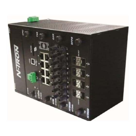
Page 8: Nt24K Rack Mount
Gigabit ports in a rugged 1U 19” rackmount enclosure. Designed to handle the most demanding environments, the NT24k includes dual power inputs, extreme operating temperature range and three slots to accommodate mix-and-match port modules. (Revised 4-9-2013) NT24k Managed Industrial Ethernet Switch User Manual & Installation Guide Page 8 of 132... - Page 9 NT24k Rack Mount, Continued … (Revised 4-9-2013) NT24k Managed Industrial Ethernet Switch User Manual & Installation Guide Page 9 of 132...
-
Page 10: Nt24K-Dr24
NT24k-DR24 The NT24k-DR24 Managed Industrial Ethernet Switch features connectivity for up to 24 Gigabit ports in a rugged DIN-rail enclosure. (Revised 4-9-2013) NT24k Managed Industrial Ethernet Switch User Manual & Installation Guide Page 10 of 132... - Page 11 NT24k-DR24,Continued… (Revised 4-9-2013) NT24k Managed Industrial Ethernet Switch User Manual & Installation Guide Page 11 of 132...
-
Page 12: Nt24K-Dr16
NT24k-DR16 The N-Tron® NT24k-DR16 Managed Industrial Ethernet Switch features connectivity for up to 16 Gigabit ports in a rugged DIN rail enclosure. (Revised 4-9-2013) NT24k Managed Industrial Ethernet Switch User Manual & Installation Guide Page 12 of 132... - Page 13 NT24k-DR16, Continued … (Revised 4-9-2013) NT24k Managed Industrial Ethernet Switch User Manual & Installation Guide Page 13 of 132...
-
Page 14: Nt24K Industrial Ethernet Switch Accessories
NTCD-CFG The configuration device is inserted in the back of the NT24k: The unit could be configured with multiple power supply configuration. (Revised 4-9-2013) NT24k Managed Industrial Ethernet Switch User Manual & Installation Guide Page 14 of 132... - Page 15 In no event shall N-Tron Corporation be liable for any incidental, special, indirect or consequential damages whatsoever included but not limited to lost profits arising out of errors or omissions in this manual or the information contained herein.
-
Page 16: Safety Warnings
See the grounding technique section of this user manual for proper ways to ground the unit. (Revised 4-9-2013) NT24k Managed Industrial Ethernet Switch User Manual & Installation Guide Page 16 of 132... - Page 17 Relay by Panasonic, Part No. TX2SS-3V, or Omron, part G6S2FDC3. (Revised 4-9-2013) NT24k Managed Industrial Ethernet Switch User Manual & Installation Guide Page 17 of 132...
-
Page 18: Installation
19" racks. As an alternative we offer our NT24k Panel Mount Assembly (P/N: NT24k-PM) which may be used to securely mount the NT24k products to a panel or other flat surface. A clearance of 1 inch should be observed on the sides, back, top and bottom to allow proper ventilation. - Page 19 No Link between ports GREEN Data is active between ports. Activity light blink rate indicates activity, not necessarily the volume of activity. Data is inactive between ports (Revised 4-9-2013) NT24k Managed Industrial Ethernet Switch User Manual & Installation Guide Page 19 of 132...
- Page 20 APPLYING POWER AND FAULT CONNECTIONS (Back View) All NT24k can operate with one power supply, either AC or DC. The Rack Mount NT24k can accept up to two power supply units. Each power supply can be AC or DC. Each low voltage DC Power supply includes redundancy (two DC supplies).
- Page 21 NT24k Fault Pins The Fault pins on the back of the NT24k can be used for an alarm contact. The current carrying capacity is 1A at 24VDC. It is normally open and the relay closes when a fault condition occurs, though this can be reversed via configuration.
-
Page 22: Connecting The Unit
Warning: Creating a port to port connection on the same switch (i.e. loop) is an illegal operation and will create a broadcast storm which will crash the network! (Revised 4-9-2013) NT24k Managed Industrial Ethernet Switch User Manual & Installation Guide Page 22 of 132... - Page 23 NT24k/NT24k-AC the power supply is isolated from chassis ground. Therefore the user must not attempt to ground the switch to earth ground via the power supply. In other N-Tron switches it is common to use the V- for the purpose of grounding. This must NOT be attempted in the NT24k or NT24k-AC.
- Page 24 RJ45 CONNECTOR CRIMP SPECIFICATIONS Please reference the illustration below for your Cat5 cable specifications: (Revised 4-9-2013) NT24k Managed Industrial Ethernet Switch User Manual & Installation Guide Page 24 of 132...
- Page 25 USB INTERFACE The NT24k switches provide a USB interface accessed via the USB connector labeled as “USB” on the back of the unit near the center. This is used to access the Command Line Interpreter (CLI) or PPP (Point- to-Point Protocol). PPP allows any configuration and status that the browser does.
-
Page 26: Overview Of Advanced Features
This feature allows grouping of high-speed connectivity and provides redundant connection between switches, so that a trunk can act as a single link between the switches. (Revised 4-9-2013) NT24k Managed Industrial Ethernet Switch User Manual & Installation Guide Page 26 of 132... -
Page 27: Quality Of Service (Qos)
PVIDs properly and configuring for all frames to exit untagged, the switch can achieve a ‘port VLAN’ configuration in which all frames in and out can be untagged, thus not requiring external devices to be VLAN cognizant. (Revised 4-9-2013) NT24k Managed Industrial Ethernet Switch User Manual & Installation Guide Page 27 of 132... -
Page 28: Rapid Spanning Tree Protocol
The NT24k switch also has the ability to allow overlapping VLANs. Overlapping VLANs give the user the ability to have one or more ports share two or more VLAN groups. For more information and examples on how this could be implemented, please see the ‘VLAN Configuration Examples’... -
Page 29: N-Ring
Point to Point Protocol (PPP) allows a browser like interface over the CLI port. Telnet Telnet allows a CLI like interface over the internet. The NT24k supports up to two concurrent Telnet users. DHCP Client The switch will automatically obtain an IP assignment from a DHCP Server, or optionally Fallback to a configured IP assignment if unable to get an IP assignment from a DHCP server. - Page 30 (2) ce dispositif doit accepter n'importe quelle interférence reçue, y compris l'interférence qui peut causer l'opération peu désirée. (Revised 4-9-2013) NT24k Managed Industrial Ethernet Switch User Manual & Installation Guide Page 30 of 132...
-
Page 31: Web Software Configuration
Web Software Configuration Web Management Enter the switch’s IP address in any web browser and login to the web management feature of the NT24k. The DHCP Client is enabled in factory defaults, with 192.168.1.210 as the faillback address. Default: User Name: admin Password: admin Up to 5 concurrent web users are allowed. -
Page 32: Web Management - Product Information Page
Web Management - Product Information Page When the administrator either first logs onto a NT24k switch or selects the page on the left, the Product Information page will be displayed. On the left hand side of the screen there is a list of configurable settings that the NT24k switch will support. - Page 33 The boot loader's software version. Loader: Copyright: The copyright. URL: The company's home page on the internet. Switch Modules The presently installed modules, including SFP transceivers. (Revised 4-9-2013) NT24k Managed Industrial Ethernet Switch User Manual & Installation Guide Page 33 of 132...
-
Page 34: Web Management - Menu Structure
Help text can be accessed from this left hand navigation as below on the right, or by pressing ‘Help’ in the upper right hand corner of each browser page to get context dependent help. Standard Menu: Advanced menu: Help Menu: (Revised 4-9-2013) NT24k Managed Industrial Ethernet Switch User Manual & Installation Guide Page 34 of 132... -
Page 35: Configuration Page
The “Factory” button resets the switch's configuration to factory defaults except for any of the user selectable items below. If a configuration device is installed, Save Configuration is then necessary to update the configuration stored on the configuration device. (Revised 4-9-2013) NT24k Managed Industrial Ethernet Switch User Manual & Installation Guide Page 35 of 132... -
Page 36: Fault Page
Indicates that the temperature of the switch is outside of the configured limits. Configuration Device: Indicates that the configuration on an installed configuration device is invalid. (Revised 4-9-2013) NT24k Managed Industrial Ethernet Switch User Manual & Installation Guide Page 36 of 132... - Page 37 (Right): Indicates a low voltage on the right power supply DC V Note: V1 and V2 Power Faults are disabled in factory defaults on a low voltage DC power supply. (Revised 4-9-2013) NT24k Managed Industrial Ethernet Switch User Manual & Installation Guide Page 37 of 132...
-
Page 38: File Transfer Page
File Transfer gives the administrator the ability to Upgrade Image or Bootloader Firmware, or to import an XML configuration file to the switch or to export a saved XML configuration file from the NT24k switch. This allows administrators to backup their configurations to a server offsite in case they need to reload their custom configurations at a later time. - Page 39 On “Import Configuration to switch” the existing Internet Address, Gateway, and Subnet Mask can be retained. Also, you can retain the current user names and passwords, and/or the currently stored SNMP settings: (Revised 4-9-2013) NT24k Managed Industrial Ethernet Switch User Manual & Installation Guide Page 39 of 132...
- Page 40 On “Export Saved Configuration from switch” pressing the “Configuration Settings” hyperlink brings up the Windows utilities to specify to just open it or where to save it and the filename. (Revised 4-9-2013) NT24k Managed Industrial Ethernet Switch User Manual & Installation Guide Page 40 of 132...
-
Page 41: System Page
The lowest temperature for the switch without causing a fault to occur. The threshold is specified as an integer in C degrees. The range is from -60°C to 100°C, and the default is product dependent. (Revised 4-9-2013) NT24k Managed Industrial Ethernet Switch User Manual & Installation Guide Page 41 of 132... - Page 42 Contains the configured Fallback IP Address of the device. The default is 192.168.1.201. Fallback Subnet Mask: Contains the configured Fallback Subnet Mask of the device. Fallback Gateway: Contains the configured Fallback Gateway of the device. (Revised 4-9-2013) NT24k Managed Industrial Ethernet Switch User Manual & Installation Guide Page 42 of 132...
-
Page 43: User Management
A page should display after the administrator clicks the Add button indicating that the user was successfully added. (Revised 4-9-2013) NT24k Managed Industrial Ethernet Switch User Manual & Installation Guide Page 43 of 132... - Page 44 Following the Remove button on the above example, the administrator can remove a user by entering in the user’s name and clicking the Remove button. A page should follow indicating that the user was successfully removed from the list. (Revised 4-9-2013) NT24k Managed Industrial Ethernet Switch User Manual & Installation Guide Page 44 of 132...
-
Page 45: Bridging - Aging Time
The default aging time is 300 seconds. After selecting the Modify button, the user will be presented with a page that allows the number to be entered and updated. (Revised 4-9-2013) NT24k Managed Industrial Ethernet Switch User Manual & Installation Guide Page 45 of 132... -
Page 46: Bridging - Multicast Addresses
Note: If there are multiple ports on different VLANs, the NT24k will apply the static multicast address to the lowest VLAN-ID that is associated with one of the ports assigned to the static multicast address. - Page 47 Multicast Group Addresses that are configured on the switch. Using the pull-down menu, the administrator should select the desired address to be removed. Then click on the Remove button at the bottom of the page. (Revised 4-9-2013) NT24k Managed Industrial Ethernet Switch User Manual & Installation Guide Page 47 of 132...
-
Page 48: Bridging - Unicast Addresses
Following the Add button on the page above, the administrator must enter a valid MAC address and associate it with a port number on the switch. Once the administrator hits the Add button, the changes will take effect instantly. (Revised 4-9-2013) NT24k Managed Industrial Ethernet Switch User Manual & Installation Guide Page 48 of 132... - Page 49 Following the Remove button on the example above, an administrator can delete a static MAC address from the list by pressing the Delete button on the page to remove the entry (Revised 4-9-2013) NT24k Managed Industrial Ethernet Switch User Manual & Installation Guide Page 49 of 132...
-
Page 50: Igmp - Configuration
Update button at the bottom of the page. (Revised 4-9-2013) NT24k Managed Industrial Ethernet Switch User Manual & Installation Guide Page 50 of 132... - Page 51 The Query Mode pull-down allows the user to set query mode for Automatic (the default), On (always), or Off (never). In Automatic multiple switches will ensure that only one switch is the active querier. (Revised 4-9-2013) NT24k Managed Industrial Ethernet Switch User Manual & Installation Guide Page 51 of 132...
- Page 52 ‘Manual’ allows only for manually set router ports. ‘None’ allows no router ports. On an N-Ring Manager, the ring ports are informatively shown as router ports. The user can specify the manual router ports: (Revised 4-9-2013) NT24k Managed Industrial Ethernet Switch User Manual & Installation Guide Page 52 of 132...
- Page 53 The default is checked. Note that IGMP Groups are not retained through a power cycle. (Revised 4-9-2013) NT24k Managed Industrial Ethernet Switch User Manual & Installation Guide Page 53 of 132...
-
Page 54: Igmp - Groups
Dynamically created Multicast group IP address. The descriptive name of the port. Port Name: VLAN ID: VLAN in which the Group IP is assigned. The range is 1-4094. (Revised 4-9-2013) NT24k Managed Industrial Ethernet Switch User Manual & Installation Guide Page 54 of 132... -
Page 55: Igmp - Rfilter Ports
Rfilter can be set for individual ports: any, all, or none. For each port, rfilter will have an impact only if that port is manually or dynamically chosen as a router port. Default configuration: (Revised 4-9-2013) NT24k Managed Industrial Ethernet Switch User Manual & Installation Guide Page 55 of 132... - Page 56 After pressing ‘Modify’, the administrator can select which ports to identify as RFilter ports or choose all ports. The administrator can view all possible ports (‘Modules’), currently installed ports, or currently linked up ports: (Revised 4-9-2013) NT24k Managed Industrial Ethernet Switch User Manual & Installation Guide Page 56 of 132...
-
Page 57: Igmp - Routers
The Routers tab under the IGMP category will display a list of Auto-detected Router IPs and the port numbers that they are associated with. The Router IP address is auto-detected. (Revised 4-9-2013) NT24k Managed Industrial Ethernet Switch User Manual & Installation Guide Page 57 of 132... -
Page 58: N-Ring - Configuration - Basic
9. Since VLANs are implemented for security reasons as well as traffic flow, N-Ring only makes minimal changes. It is up to the administrator to ensure that VLANs are configured correctly on the N-Ring manager and all N-Ring members. (Revised 4-9-2013) NT24k Managed Industrial Ethernet Switch User Manual & Installation Guide Page 58 of 132... - Page 59 A5/B3) as N-Ring ports. If N-Ring Mode is “Manager”, then VLAN ID can be set to a unique VLAN id (1 ~ 4094). Default is 3333. (Revised 4-9-2013) NT24k Managed Industrial Ethernet Switch User Manual & Installation Guide Page 59 of 132...
-
Page 60: N-Ring - Configuration - Port Sets
Pressing ‘Modify’ on the page above yields this page: To delete a port set, click the checkbox in the desired row and then click the Delete button. (Revised 4-9-2013) NT24k Managed Industrial Ethernet Switch User Manual & Installation Guide Page 60 of 132... - Page 61 Pressing ‘Add’ on the page above yields: The N-Ring ports can be selected by pulldown. In this mode port sets can be deleted from a pulldown. (Revised 4-9-2013) NT24k Managed Industrial Ethernet Switch User Manual & Installation Guide Page 61 of 132...
-
Page 62: N-Ring - Configuration - Advanced
The amount of time to wait in seconds to receive N-Ring frames on any auto member port (at boot up) before assuming the switch is not part of an N-Ring. Detection Timeout: (Revised 4-9-2013) NT24k Managed Industrial Ethernet Switch User Manual & Installation Guide Page 62 of 132... - Page 63 The amount of time, in milliseconds, that must elapse before the ring is allowed to Entering Broken go back into the broken state. The default is 3000. State: (Revised 4-9-2013) NT24k Managed Industrial Ethernet Switch User Manual & Installation Guide Page 63 of 132...
-
Page 64: N-Ring - Status
If N-Ring mode is inactive Auto Member, the following data will be shown: If N-Ring mode is Active Auto Member, the following data will be shown: (Revised 4-9-2013) NT24k Managed Industrial Ethernet Switch User Manual & Installation Guide Page 64 of 132... - Page 65 Subnet Mask: The Subnet Mask of the switch. Name: The name of the switch. (Set on the switch) Ports: The N-Ring ports of the switch. Notes: Information regarding the switch. (Revised 4-9-2013) NT24k Managed Industrial Ethernet Switch User Manual & Installation Guide Page 65 of 132...
- Page 66 Note “Switch order may be incorrect and all switches may not be shown.” in yellow. This is because since the Sign On frames cannot get around the N-Ring the data may not be updated since the last time they did. (Revised 4-9-2013) NT24k Managed Industrial Ethernet Switch User Manual & Installation Guide Page 66 of 132...
-
Page 67: N-View - Configuration
Decreasing the interval will allow N-View to report more frequently. The range is 5 to 500 seconds. Additionally, you may Disable or Enable N-View altogether. (Revised 4-9-2013) NT24k Managed Industrial Ethernet Switch User Manual & Installation Guide Page 67 of 132... -
Page 68: N-View - Ports
N-View – Ports The Ports tab under the N-View category will display a list of all the configured ports on the NT24k unit along with the ports transmitting N-View related multicast packets and MIB stats respectively. (Revised 4-9-2013) NT24k Managed Industrial Ethernet Switch User Manual & Installation Guide Page 68 of 132... - Page 69 N-View related multicast out of the port and if MIB stats are sent out for those ports. The administrator can view ports that are possible to install (Modules), currently installed, or currently linked up. (Revised 4-9-2013) NT24k Managed Industrial Ethernet Switch User Manual & Installation Guide Page 69 of 132...
-
Page 70: Ports - Configuration
The Configuration tab under the Ports category will show a detailed overview of all the ports on the switch. The administrator can view ports that are possible to install (Modules), currently installed, or currently linked up. The following information is displayed.: (Revised 4-9-2013) NT24k Managed Industrial Ethernet Switch User Manual & Installation Guide Page 70 of 132... - Page 71 Admin Status Speed and Duplex Flow Control Cross Over PVID Usage Alarm Low Usage Alarm High (Revised 4-9-2013) NT24k Managed Industrial Ethernet Switch User Manual & Installation Guide Page 71 of 132...
-
Page 72: Ports - Mirroring
‘Mirrored Data Only’ can be selected for mirrored data only to be transmitted to the destination port, as opposed to mirrored data and whatever other data is otherwise destined for the destination Port. (Revised 4-9-2013) NT24k Managed Industrial Ethernet Switch User Manual & Installation Guide Page 72 of 132... -
Page 73: Ports - Qos
(0-7, 7=highest priority). If the ingress frame is an IP packet, the RFC 2474 DSCP field in the packet will be passed unchanged to the egress frame. (Revised 4-9-2013) NT24k Managed Industrial Ethernet Switch User Manual & Installation Guide Page 73 of 132... - Page 74 IEEE802.1p User Priority value if not otherwise assigned by DSCP or IEEE802.1p processing. The range is 0-7, highest priority=7. The default value is 1. (Revised 4-9-2013) NT24k Managed Industrial Ethernet Switch User Manual & Installation Guide Page 74 of 132...
-
Page 75: Ports - Rate Limiting
Ports – Rate Limiting The Rate Limiting/link will display all the ports tht are installed in the NT24k unit and will list the Pass Rate Percentage for each port for each of: Broadcast, Multicast, Unknown Unicast, and Known Unicast. A packet type will be affected when the checkbox is selected if it exceeds the total number of packets subject to the ingress rate limit percentage within an assigned time period. - Page 76 The following information is displayed.: Note: Unicast packets with destinations not in the ARL table can be rate limited rather than all being Flooded. That is ‘Unknown Unicast’. (Revised 4-9-2013) NT24k Managed Industrial Ethernet Switch User Manual & Installation Guide Page 76 of 132...
-
Page 77: Ports - Status - Statistics
The Clear All Ports button will reset all counters for all ports, including the selected port. (Revised 4-9-2013) NT24k Managed Industrial Ethernet Switch User Manual & Installation Guide Page 77 of 132... -
Page 78: Ports - Status - Utilization
Ports – Status - Utilization Shows a bandwidth percentage graph of all the ports. The graph is scaled based on the Scale pull-down menu selection. (Revised 4-9-2013) NT24k Managed Industrial Ethernet Switch User Manual & Installation Guide Page 78 of 132... -
Page 79: Ports - Trunking
3. If a port is both a RSTP port and an enabled trunk group member, then the port will be disabled for RSTP. The RSTP port status can be seen under advanced RSTP ports. (Revised 4-9-2013) NT24k Managed Industrial Ethernet Switch User Manual & Installation Guide Page 79 of 132... - Page 80 By selecting ‘Add’ you can first decide to view ports that are possible to install (Modules), currently installed, or currently linked up. Then you can specify a trunk group to add. (Revised 4-9-2013) NT24k Managed Industrial Ethernet Switch User Manual & Installation Guide Page 80 of 132...
- Page 81 By selecting a trunk ID hyperlink from the Port Trunking Configuration View, you can first decide to view ports that are possible to install (Modules), currently installed, or currently linked up. Then you can specify changes to a trunk group.. (Revised 4-9-2013) NT24k Managed Industrial Ethernet Switch User Manual & Installation Guide Page 81 of 132...
-
Page 82: Ports - Ppp
PPP Switch IP Address The IP address for the switch side of the PPP link. PPP PC IP Address The IP address for the PC side of the PPP link. (Revised 4-9-2013) NT24k Managed Industrial Ethernet Switch User Manual & Installation Guide Page 82 of 132... -
Page 83: Rstp - Bridge
RSTP. The RSTP port status can be seen under advanced RSTP ports. 4. It is recommended that RSTP rings consist of RSTP capable switches. 5. RSTP is supported on only one VLAN. (Revised 4-9-2013) NT24k Managed Industrial Ethernet Switch User Manual & Installation Guide Page 83 of 132... - Page 84 The cost of the path to the Root Bridge via the Root Port of this bridge. Root Port: The Root Port of this Bridge. The Root Port provides the lowest cost path from this Bridge to the Root Bridge. (Revised 4-9-2013) NT24k Managed Industrial Ethernet Switch User Manual & Installation Guide Page 84 of 132...
- Page 85 RSTP Status This is the current status of the RSTP protocol on this bridge. This may be RSTP, Force STP, or Disabled (Revised 4-9-2013) NT24k Managed Industrial Ethernet Switch User Manual & Installation Guide Page 85 of 132...
- Page 86 RSTP – Bridge, Continued … The administrator can modify the Bridge parameters by pressing the ‘Modify’ button on the above page. (Revised 4-9-2013) NT24k Managed Industrial Ethernet Switch User Manual & Installation Guide Page 86 of 132...
-
Page 87: Rstp - Ports
In the example below, A2 is a redundant port with port A1, therefore A1 is forwarding and A2 is discarding. When operating in a VLAN with legacy STP devices, use Auto Edge = Disabled for Bridge Ports. (Revised 4-9-2013) NT24k Managed Industrial Ethernet Switch User Manual & Installation Guide Page 87 of 132... - Page 88 By clicking on the hyperlink for the Port Number on the screen above, one can then get a screen from which to modify the Bridge Port parameters: Path Cost, Priority, Admin Edge, Auto Edge, and Point to Point: (Revised 4-9-2013) NT24k Managed Industrial Ethernet Switch User Manual & Installation Guide Page 88 of 132...
-
Page 89: Snmp - Configuration
This allows for control of which SNMP traps will be sent by this switch. Each of the 4 Traps: available traps: Cold Start, Authentication, Warm Start and Link Status can be enabled or disabled individually. (Revised 4-9-2013) NT24k Managed Industrial Ethernet Switch User Manual & Installation Guide Page 89 of 132... -
Page 90: Snmp - Trap Stations
This field represents the Target Parameter entry(TRAPv1, TRAPv2, etc) to be used for sending traps to the Management Station. Pressing the ‘Add’ button above allows one to add a Trap Station via this screen: (Revised 4-9-2013) NT24k Managed Industrial Ethernet Switch User Manual & Installation Guide Page 90 of 132... - Page 91 SNMP V3 client and the values below may be invalid if they are changed by an SNMP administrator. Username: initial Privacy Password: privpass authpass Authentication Password: Authentication Protocol: (Revised 4-9-2013) NT24k Managed Industrial Ethernet Switch User Manual & Installation Guide Page 91 of 132...
-
Page 92: Vlan
Specifies whether or not to filter out ingress frames when a VID violation is Ports: detected on the selected ports. Primary Management The default egress VLAN used for communications initiated by the switch VLAN: i.e. DCHP requests. (Revised 4-9-2013) NT24k Managed Industrial Ethernet Switch User Manual & Installation Guide Page 92 of 132... - Page 93 Pressing the ‘Modify’ button on the screen above, you can first decide to view ports that are possible to install (Modules), currently installed, or currently linked up. (Revised 4-9-2013) NT24k Managed Industrial Ethernet Switch User Manual & Installation Guide Page 93 of 132...
- Page 94 Then you can specify general VLAN changes, as below in the top frame: Pressing ‘Delete’ in the lower frame of the screen above removes that VLAN. (Revised 4-9-2013) NT24k Managed Industrial Ethernet Switch User Manual & Installation Guide Page 94 of 132...
- Page 95 VLAN, Continued … Pressing ‘Add’ on the screen above allows entry of a new VLAN: (Revised 4-9-2013) NT24k Managed Industrial Ethernet Switch User Manual & Installation Guide Page 95 of 132...
- Page 96 VLAN, Continued … Selecting the Port Number hyperlink in the lower frame of the screen two above allows changes to that VLAN: (Revised 4-9-2013) NT24k Managed Industrial Ethernet Switch User Manual & Installation Guide Page 96 of 132...
-
Page 97: Help - Overview
When the Overview tab of the Help menu is clicked on, you will see the Overview page that will have some basic definitions and more specific choices at the top of the screen. (Revised 4-9-2013) NT24k Managed Industrial Ethernet Switch User Manual & Installation Guide Page 97 of 132... - Page 98 Help – Overview, Continued (Revised 4-9-2013) NT24k Managed Industrial Ethernet Switch User Manual & Installation Guide Page 98 of 132...
-
Page 99: Help - Other
Specific help can be had using the left hand navigation as shown above, or by asking for help in context on any given browser page. (Revised 4-9-2013) NT24k Managed Industrial Ethernet Switch User Manual & Installation Guide Page 99 of 132... -
Page 100: Cli Commands
‘admin’. Each command includes help and syntax examples. Below are a few common CLI examples: Get system information: (Revised 4-9-2013) NT24k Managed Industrial Ethernet Switch User Manual & Installation Guide Page 100 of 132... - Page 101 CLI Commands, Continued, … Set IP Mode to ‘static’:: Show the static IP: Set a static IP: (mask and gateway are optional) Save the configuration: (Revised 4-9-2013) NT24k Managed Industrial Ethernet Switch User Manual & Installation Guide Page 101 of 132...
- Page 102 CLI Commands, Continued… Reboot: (Revised 4-9-2013) NT24k Managed Industrial Ethernet Switch User Manual & Installation Guide Page 102 of 132...
-
Page 103: Appendix A - Xml Configuration File - Factory Defaults
<Web>Disabled</Web> </Fault> <Fault> <Contact>Disabled</Contact> <Id>1</Id> <Led>Disabled</Led> <Web>Disabled</Web> </Fault> <Fault> <Contact>Disabled</Contact> <Id>2</Id> <Led>Disabled</Led> <Web>Disabled</Web> </Fault> <Fault> <Contact>Disabled</Contact> <Id>3</Id> <Led>Disabled</Led> <Web>Disabled</Web> </Fault> <Fault> <Contact>Disabled</Contact> <Id>4</Id> <Led>Disabled</Led> (Revised 4-9-2013) NT24k Managed Industrial Ethernet Switch User Manual & Installation Guide Page 103 of 132... - Page 104 </Fault> <Fault> <Contact>Enabled</Contact> <Id>9</Id> <Led>Enabled</Led> <Web>Enabled</Web> </Fault> <Fault> <Contact>Enabled</Contact> <Id>10</Id> <Led>Enabled</Led> <Web>Enabled</Web> </Fault> <Fault> <Contact>Enabled</Contact> <Id>11</Id> <Led>Enabled</Led> <Web>Enabled</Web> </Fault> <Fault> <Contact>Enabled</Contact> <Id>12</Id> <Led>Enabled</Led> <Web>Enabled</Web> (Revised 4-9-2013) NT24k Managed Industrial Ethernet Switch User Manual & Installation Guide Page 104 of 132...
- Page 105 <ManualRouterPorts>None</ManualRouterPorts> <QuerryMode>Auto</QuerryMode> <RemoveUnusedGroups>Enabled</RemoveUnusedGroups> <RFilterPorts>All</RFilterPorts> <RouterMode>Auto</RouterMode> <Status>Enabled</Status> </IgmpConfig> </IgmpGroup> <MirrorGroup> <MirrorConfig> <Destination>A1</Destination> <MirroredDataOnly>Disabled</MirroredDataOnly> <RxSourcePorts>None</RxSourcePorts> <Status>Disabled</Status> <TxSourcePorts>None</TxSourcePorts> </MirrorConfig> </MirrorGroup> <NringGroup> <NringConfig> <AutoMemberDetectionSeconds>4</AutoMemberDetectionSeconds> <HealthMaxMissed>2</HealthMaxMissed> <HealthMs>10</HealthMs> <HysteresisMs>3000</HysteresisMs> <KeepAliveSeconds>31</KeepAliveSeconds> (Revised 4-9-2013) NT24k Managed Industrial Ethernet Switch User Manual & Installation Guide Page 105 of 132...
- Page 106 <SendAutocastPorts>All</SendAutocastPorts> <SendMibStatsPorts>All</SendMibStatsPorts> <Status>Enabled</Status> </NViewConfig> </NViewGroup> <PortGroup> <PortConfig> <Ports> <Port> <AdminStatus>Enabled</AdminStatus> <AutoNegotiate>Enabled</AutoNegotiate> <CrossOver>Auto</CrossOver> <Duplex>Full</Duplex> <FlowControl>Disabled</FlowControl> <PortNumber>A1</PortNumber> <PortUsageAlarms> <UsageAlarmHigh>100</UsageAlarmHigh> <UsageAlarmLow>0</UsageAlarmLow> </PortUsageAlarms> <PVID>1</PVID> <Qos8021p>Enabled</Qos8021p> <QosDSCP>Enabled</QosDSCP> <QosPriorityValue>1</QosPriorityValue> <Speed>1000</Speed> (Revised 4-9-2013) NT24k Managed Industrial Ethernet Switch User Manual & Installation Guide Page 106 of 132...
- Page 107 <PortUsageAlarms> <UsageAlarmHigh>100</UsageAlarmHigh> <UsageAlarmLow>0</UsageAlarmLow> </PortUsageAlarms> <PVID>1</PVID> <Qos8021p>Enabled</Qos8021p> <QosDSCP>Enabled</QosDSCP> <QosPriorityValue>1</QosPriorityValue> <Speed>1000</Speed> </Port> <Port> <AdminStatus>Enabled</AdminStatus> <AutoNegotiate>Enabled</AutoNegotiate> <CrossOver>Auto</CrossOver> <Duplex>Full</Duplex> <FlowControl>Disabled</FlowControl> <PortNumber>A4</PortNumber> <PortUsageAlarms> <UsageAlarmHigh>100</UsageAlarmHigh> <UsageAlarmLow>0</UsageAlarmLow> </PortUsageAlarms> <PVID>1</PVID> <Qos8021p>Enabled</Qos8021p> <QosDSCP>Enabled</QosDSCP> (Revised 4-9-2013) NT24k Managed Industrial Ethernet Switch User Manual & Installation Guide Page 107 of 132...
- Page 108 <FlowControl>Disabled</FlowControl> <PortNumber>A6</PortNumber> <PortUsageAlarms> <UsageAlarmHigh>100</UsageAlarmHigh> <UsageAlarmLow>0</UsageAlarmLow> </PortUsageAlarms> <PVID>1</PVID> <Qos8021p>Enabled</Qos8021p> <QosDSCP>Enabled</QosDSCP> <QosPriorityValue>1</QosPriorityValue> <Speed>1000</Speed> </Port> <Port> <AdminStatus>Enabled</AdminStatus> <AutoNegotiate>Enabled</AutoNegotiate> <CrossOver>Auto</CrossOver> <Duplex>Full</Duplex> <FlowControl>Disabled</FlowControl> <PortNumber>A7</PortNumber> <PortUsageAlarms> <UsageAlarmHigh>100</UsageAlarmHigh> <UsageAlarmLow>0</UsageAlarmLow> </PortUsageAlarms> <PVID>1</PVID> (Revised 4-9-2013) NT24k Managed Industrial Ethernet Switch User Manual & Installation Guide Page 108 of 132...
- Page 109 <CrossOver>Auto</CrossOver> <Duplex>Full</Duplex> <FlowControl>Disabled</FlowControl> <PortNumber>B1</PortNumber> <PortUsageAlarms> <UsageAlarmHigh>100</UsageAlarmHigh> <UsageAlarmLow>0</UsageAlarmLow> </PortUsageAlarms> <PVID>1</PVID> <Qos8021p>Enabled</Qos8021p> <QosDSCP>Enabled</QosDSCP> <QosPriorityValue>1</QosPriorityValue> <Speed>1000</Speed> </Port> <Port> <AdminStatus>Enabled</AdminStatus> <AutoNegotiate>Enabled</AutoNegotiate> <CrossOver>Auto</CrossOver> <Duplex>Full</Duplex> <FlowControl>Disabled</FlowControl> <PortNumber>B2</PortNumber> <PortUsageAlarms> <UsageAlarmHigh>100</UsageAlarmHigh> <UsageAlarmLow>0</UsageAlarmLow> (Revised 4-9-2013) NT24k Managed Industrial Ethernet Switch User Manual & Installation Guide Page 109 of 132...
- Page 110 <AdminStatus>Enabled</AdminStatus> <AutoNegotiate>Enabled</AutoNegotiate> <CrossOver>Auto</CrossOver> <Duplex>Full</Duplex> <FlowControl>Disabled</FlowControl> <PortNumber>B4</PortNumber> <PortUsageAlarms> <UsageAlarmHigh>100</UsageAlarmHigh> <UsageAlarmLow>0</UsageAlarmLow> </PortUsageAlarms> <PVID>1</PVID> <Qos8021p>Enabled</Qos8021p> <QosDSCP>Enabled</QosDSCP> <QosPriorityValue>1</QosPriorityValue> <Speed>1000</Speed> </Port> <Port> <AdminStatus>Enabled</AdminStatus> <AutoNegotiate>Enabled</AutoNegotiate> <CrossOver>Auto</CrossOver> <Duplex>Full</Duplex> <FlowControl>Disabled</FlowControl> <PortNumber>B5</PortNumber> <PortUsageAlarms> (Revised 4-9-2013) NT24k Managed Industrial Ethernet Switch User Manual & Installation Guide Page 110 of 132...
- Page 111 </Port> <Port> <AdminStatus>Enabled</AdminStatus> <AutoNegotiate>Enabled</AutoNegotiate> <CrossOver>Auto</CrossOver> <Duplex>Full</Duplex> <FlowControl>Disabled</FlowControl> <PortNumber>B7</PortNumber> <PortUsageAlarms> <UsageAlarmHigh>100</UsageAlarmHigh> <UsageAlarmLow>0</UsageAlarmLow> </PortUsageAlarms> <PVID>1</PVID> <Qos8021p>Enabled</Qos8021p> <QosDSCP>Enabled</QosDSCP> <QosPriorityValue>1</QosPriorityValue> <Speed>1000</Speed> </Port> <Port> <AdminStatus>Enabled</AdminStatus> <AutoNegotiate>Enabled</AutoNegotiate> <CrossOver>Auto</CrossOver> <Duplex>Full</Duplex> <FlowControl>Disabled</FlowControl> (Revised 4-9-2013) NT24k Managed Industrial Ethernet Switch User Manual & Installation Guide Page 111 of 132...
- Page 112 <QosPriorityValue>1</QosPriorityValue> <Speed>1000</Speed> </Port> <Port> <AdminStatus>Enabled</AdminStatus> <AutoNegotiate>Enabled</AutoNegotiate> <CrossOver>Auto</CrossOver> <Duplex>Full</Duplex> <FlowControl>Disabled</FlowControl> <PortNumber>C2</PortNumber> <PortUsageAlarms> <UsageAlarmHigh>100</UsageAlarmHigh> <UsageAlarmLow>0</UsageAlarmLow> </PortUsageAlarms> <PVID>1</PVID> <Qos8021p>Enabled</Qos8021p> <QosDSCP>Enabled</QosDSCP> <QosPriorityValue>1</QosPriorityValue> <Speed>1000</Speed> </Port> <Port> <AdminStatus>Enabled</AdminStatus> <AutoNegotiate>Enabled</AutoNegotiate> <CrossOver>Auto</CrossOver> (Revised 4-9-2013) NT24k Managed Industrial Ethernet Switch User Manual & Installation Guide Page 112 of 132...
- Page 113 <Qos8021p>Enabled</Qos8021p> <QosDSCP>Enabled</QosDSCP> <QosPriorityValue>1</QosPriorityValue> <Speed>1000</Speed> </Port> <Port> <AdminStatus>Enabled</AdminStatus> <AutoNegotiate>Enabled</AutoNegotiate> <CrossOver>Auto</CrossOver> <Duplex>Full</Duplex> <FlowControl>Disabled</FlowControl> <PortNumber>C5</PortNumber> <PortUsageAlarms> <UsageAlarmHigh>100</UsageAlarmHigh> <UsageAlarmLow>0</UsageAlarmLow> </PortUsageAlarms> <PVID>1</PVID> <Qos8021p>Enabled</Qos8021p> <QosDSCP>Enabled</QosDSCP> <QosPriorityValue>1</QosPriorityValue> <Speed>1000</Speed> </Port> <Port> <AdminStatus>Enabled</AdminStatus> (Revised 4-9-2013) NT24k Managed Industrial Ethernet Switch User Manual & Installation Guide Page 113 of 132...
- Page 114 </PortUsageAlarms> <PVID>1</PVID> <Qos8021p>Enabled</Qos8021p> <QosDSCP>Enabled</QosDSCP> <QosPriorityValue>1</QosPriorityValue> <Speed>1000</Speed> </Port> <Port> <AdminStatus>Enabled</AdminStatus> <AutoNegotiate>Enabled</AutoNegotiate> <CrossOver>Auto</CrossOver> <Duplex>Full</Duplex> <FlowControl>Disabled</FlowControl> <PortNumber>C8</PortNumber> <PortUsageAlarms> <UsageAlarmHigh>100</UsageAlarmHigh> <UsageAlarmLow>0</UsageAlarmLow> </PortUsageAlarms> <PVID>1</PVID> <Qos8021p>Enabled</Qos8021p> <QosDSCP>Enabled</QosDSCP> <QosPriorityValue>1</QosPriorityValue> <Speed>1000</Speed> </Port> (Revised 4-9-2013) NT24k Managed Industrial Ethernet Switch User Manual & Installation Guide Page 114 of 132...
- Page 115 <Multicast>Disabled</Multicast> <PortNumber>A3</PortNumber> <RateLimit>3</RateLimit> <UnknownUnicast>Disabled</UnknownUnicast> </Limit> <Limit> <Broadcast>Enabled</Broadcast> <KnownUnicast>Disabled</KnownUnicast> <Multicast>Disabled</Multicast> <PortNumber>A4</PortNumber> <RateLimit>3</RateLimit> <UnknownUnicast>Disabled</UnknownUnicast> </Limit> <Limit> <Broadcast>Enabled</Broadcast> <KnownUnicast>Disabled</KnownUnicast> <Multicast>Disabled</Multicast> <PortNumber>A5</PortNumber> <RateLimit>3</RateLimit> <UnknownUnicast>Disabled</UnknownUnicast> </Limit> <Limit> <Broadcast>Enabled</Broadcast> <KnownUnicast>Disabled</KnownUnicast> (Revised 4-9-2013) NT24k Managed Industrial Ethernet Switch User Manual & Installation Guide Page 115 of 132...
- Page 116 <PortNumber>B1</PortNumber> <RateLimit>3</RateLimit> <UnknownUnicast>Disabled</UnknownUnicast> </Limit> <Limit> <Broadcast>Enabled</Broadcast> <KnownUnicast>Disabled</KnownUnicast> <Multicast>Disabled</Multicast> <PortNumber>B2</PortNumber> <RateLimit>3</RateLimit> <UnknownUnicast>Disabled</UnknownUnicast> </Limit> <Limit> <Broadcast>Enabled</Broadcast> <KnownUnicast>Disabled</KnownUnicast> <Multicast>Disabled</Multicast> <PortNumber>B3</PortNumber> <RateLimit>3</RateLimit> <UnknownUnicast>Disabled</UnknownUnicast> </Limit> <Limit> <Broadcast>Enabled</Broadcast> <KnownUnicast>Disabled</KnownUnicast> <Multicast>Disabled</Multicast> (Revised 4-9-2013) NT24k Managed Industrial Ethernet Switch User Manual & Installation Guide Page 116 of 132...
- Page 117 <RateLimit>3</RateLimit> <UnknownUnicast>Disabled</UnknownUnicast> </Limit> <Limit> <Broadcast>Enabled</Broadcast> <KnownUnicast>Disabled</KnownUnicast> <Multicast>Disabled</Multicast> <PortNumber>B8</PortNumber> <RateLimit>3</RateLimit> <UnknownUnicast>Disabled</UnknownUnicast> </Limit> <Limit> <Broadcast>Enabled</Broadcast> <KnownUnicast>Disabled</KnownUnicast> <Multicast>Disabled</Multicast> <PortNumber>C1</PortNumber> <RateLimit>3</RateLimit> <UnknownUnicast>Disabled</UnknownUnicast> </Limit> <Limit> <Broadcast>Enabled</Broadcast> <KnownUnicast>Disabled</KnownUnicast> <Multicast>Disabled</Multicast> <PortNumber>C2</PortNumber> (Revised 4-9-2013) NT24k Managed Industrial Ethernet Switch User Manual & Installation Guide Page 117 of 132...
- Page 118 <UnknownUnicast>Disabled</UnknownUnicast> </Limit> <Limit> <Broadcast>Enabled</Broadcast> <KnownUnicast>Disabled</KnownUnicast> <Multicast>Disabled</Multicast> <PortNumber>C6</PortNumber> <RateLimit>3</RateLimit> <UnknownUnicast>Disabled</UnknownUnicast> </Limit> <Limit> <Broadcast>Enabled</Broadcast> <KnownUnicast>Disabled</KnownUnicast> <Multicast>Disabled</Multicast> <PortNumber>C7</PortNumber> <RateLimit>3</RateLimit> <UnknownUnicast>Disabled</UnknownUnicast> </Limit> <Limit> <Broadcast>Enabled</Broadcast> <KnownUnicast>Disabled</KnownUnicast> <Multicast>Disabled</Multicast> <PortNumber>C8</PortNumber> <RateLimit>3</RateLimit> (Revised 4-9-2013) NT24k Managed Industrial Ethernet Switch User Manual & Installation Guide Page 118 of 132...
- Page 119 </Port> <Port> <AdminEdge>Disabled</AdminEdge> <AdminPtpMac>Auto</AdminPtpMac> <AutoEdge>Enabled</AutoEdge> <PathCost>Auto</PathCost> <PortNumber>A2</PortNumber> <PortPriorityStep>128</PortPriorityStep> <VlanId>1</VlanId> </Port> <Port> <AdminEdge>Disabled</AdminEdge> <AdminPtpMac>Auto</AdminPtpMac> <AutoEdge>Enabled</AutoEdge> <PathCost>Auto</PathCost> <PortNumber>A3</PortNumber> <PortPriorityStep>128</PortPriorityStep> <VlanId>1</VlanId> </Port> <Port> <AdminEdge>Disabled</AdminEdge> <AdminPtpMac>Auto</AdminPtpMac> <AutoEdge>Enabled</AutoEdge> <PathCost>Auto</PathCost> (Revised 4-9-2013) NT24k Managed Industrial Ethernet Switch User Manual & Installation Guide Page 119 of 132...
- Page 120 <AutoEdge>Enabled</AutoEdge> <PathCost>Auto</PathCost> <PortNumber>A7</PortNumber> <PortPriorityStep>128</PortPriorityStep> <VlanId>1</VlanId> </Port> <Port> <AdminEdge>Disabled</AdminEdge> <AdminPtpMac>Auto</AdminPtpMac> <AutoEdge>Enabled</AutoEdge> <PathCost>Auto</PathCost> <PortNumber>A8</PortNumber> <PortPriorityStep>128</PortPriorityStep> <VlanId>1</VlanId> </Port> <Port> <AdminEdge>Disabled</AdminEdge> <AdminPtpMac>Auto</AdminPtpMac> <AutoEdge>Enabled</AutoEdge> <PathCost>Auto</PathCost> <PortNumber>B1</PortNumber> <PortPriorityStep>128</PortPriorityStep> <VlanId>1</VlanId> </Port> (Revised 4-9-2013) NT24k Managed Industrial Ethernet Switch User Manual & Installation Guide Page 120 of 132...
- Page 121 <VlanId>1</VlanId> </Port> <Port> <AdminEdge>Disabled</AdminEdge> <AdminPtpMac>Auto</AdminPtpMac> <AutoEdge>Enabled</AutoEdge> <PathCost>Auto</PathCost> <PortNumber>B5</PortNumber> <PortPriorityStep>128</PortPriorityStep> <VlanId>1</VlanId> </Port> <Port> <AdminEdge>Disabled</AdminEdge> <AdminPtpMac>Auto</AdminPtpMac> <AutoEdge>Enabled</AutoEdge> <PathCost>Auto</PathCost> <PortNumber>B6</PortNumber> <PortPriorityStep>128</PortPriorityStep> <VlanId>1</VlanId> </Port> <Port> <AdminEdge>Disabled</AdminEdge> <AdminPtpMac>Auto</AdminPtpMac> <AutoEdge>Enabled</AutoEdge> (Revised 4-9-2013) NT24k Managed Industrial Ethernet Switch User Manual & Installation Guide Page 121 of 132...
- Page 122 <AdminPtpMac>Auto</AdminPtpMac> <AutoEdge>Enabled</AutoEdge> <PathCost>Auto</PathCost> <PortNumber>C2</PortNumber> <PortPriorityStep>128</PortPriorityStep> <VlanId>1</VlanId> </Port> <Port> <AdminEdge>Disabled</AdminEdge> <AdminPtpMac>Auto</AdminPtpMac> <AutoEdge>Enabled</AutoEdge> <PathCost>Auto</PathCost> <PortNumber>C3</PortNumber> <PortPriorityStep>128</PortPriorityStep> <VlanId>1</VlanId> </Port> <Port> <AdminEdge>Disabled</AdminEdge> <AdminPtpMac>Auto</AdminPtpMac> <AutoEdge>Enabled</AutoEdge> <PathCost>Auto</PathCost> <PortNumber>C4</PortNumber> <PortPriorityStep>128</PortPriorityStep> <VlanId>1</VlanId> (Revised 4-9-2013) NT24k Managed Industrial Ethernet Switch User Manual & Installation Guide Page 122 of 132...
- Page 123 <PortPriorityStep>128</PortPriorityStep> <VlanId>1</VlanId> </Port> <Port> <AdminEdge>Disabled</AdminEdge> <AdminPtpMac>Auto</AdminPtpMac> <AutoEdge>Enabled</AutoEdge> <PathCost>Auto</PathCost> <PortNumber>C8</PortNumber> <PortPriorityStep>128</PortPriorityStep> <VlanId>1</VlanId> </Port> </RstpPorts> </RstpConfig> </RstpGroup> <SnmpGroup> <SnmpConfig> <Authenticate>Disabled</Authenticate> <ColdStart>Disabled</ColdStart> <LinkStatus>Disabled</LinkStatus> <Status>Enabled</Status> <TrapDelay>40</TrapDelay> <V3Accesses> <V3Access> (Revised 4-9-2013) NT24k Managed Industrial Ethernet Switch User Manual & Installation Guide Page 123 of 132...
- Page 124 <Level>1</Level> <Match>1</Match> <Model>0</Model> <NotifyView>mibView</NotifyView> <Prefix></Prefix> <ReadView>mibView</ReadView> <Status>1</Status> <Storage>3</Storage> <WriteView>mibView</WriteView> </V3Access> <V3Access> <GroupName>group1</GroupName> <Level>1</Level> <Match>1</Match> <Model>2</Model> <NotifyView>internet</NotifyView> <Prefix></Prefix> <ReadView>internet</ReadView> <Status>1</Status> <Storage>3</Storage> <WriteView>internet</WriteView> </V3Access> <V3Access> <GroupName>v3AuthPrivGroup</GroupName> (Revised 4-9-2013) NT24k Managed Industrial Ethernet Switch User Manual & Installation Guide Page 124 of 132...
- Page 125 <ContextName></ContextName> <Index>get</Index> <SecurityName>get</SecurityName> <Status>1</Status> <Storage>3</Storage> <TransportTag></TransportTag> </V3Community> <V3Community> <CommunityName>public</CommunityName> <ContextEngineId>80006edd030007af7d9560</ContextEngineId> <ContextName></ContextName> <Index>trap</Index> <SecurityName>trap</SecurityName> <Status>1</Status> <Storage>3</Storage> <TransportTag></TransportTag> </V3Community> </V3Communities> <V3Contexts> <V3Context> <Context></Context> </V3Context> </V3Contexts> <V3Engines> (Revised 4-9-2013) NT24k Managed Industrial Ethernet Switch User Manual & Installation Guide Page 125 of 132...
- Page 126 <Storage>3</Storage> <UserName>get</UserName> </V3Group> <V3Group> <GroupName>mibWrite</GroupName> <Model>1</Model> <Status>1</Status> <Storage>3</Storage> <UserName>set</UserName> </V3Group> <V3Group> <GroupName>mibWrite</GroupName> <Model>2</Model> <Status>1</Status> <Storage>3</Storage> <UserName>set</UserName> </V3Group> <V3Group> <GroupName>mibNotify</GroupName> <Model>1</Model> <Status>1</Status> <Storage>3</Storage> <UserName>trap</UserName> </V3Group> (Revised 4-9-2013) NT24k Managed Industrial Ethernet Switch User Manual & Installation Guide Page 126 of 132...
- Page 127 <ContextEngineId>80006edd030007af7d9560</ContextEngineId> <ContextName></ContextName> <MultipleTargetOut>group1</MultipleTargetOut> <ProxyName>trap_proxy</ProxyName> <ProxyType>3</ProxyType> <SingleTargetOut></SingleTargetOut> <Status>1</Status> <Storage>3</Storage> <TargetParamsIn>trap</TargetParamsIn> </V3Proxy> <V3Proxy> <ContextEngineId>80006edd030007af7d9560</ContextEngineId> <ContextName></ContextName> <MultipleTargetOut>group1</MultipleTargetOut> <ProxyName>inform_proxy</ProxyName> <ProxyType>4</ProxyType> <SingleTargetOut></SingleTargetOut> <Status>1</Status> <Storage>3</Storage> <TargetParamsIn>NoAuthNoPriv-md5</TargetParamsIn> </V3Proxy> <V3Proxy> <ContextEngineId>80006edd030007af7d9560</ContextEngineId> <ContextName></ContextName> (Revised 4-9-2013) NT24k Managed Industrial Ethernet Switch User Manual & Installation Guide Page 127 of 132...
- Page 128 <MpModel>3</MpModel> <Name>AuthPriv-md5</Name> <SecLevel>3</SecLevel> <SecModel>3</SecModel> <SecName>initialmd5</SecName> <Status>1</Status> <Storage>3</Storage> </TargetParameter> <TargetParameter> <MpModel>3</MpModel> <Name>AuthNoPriv-md5</Name> <SecLevel>2</SecLevel> <SecModel>3</SecModel> <SecName>initialmd5</SecName> <Status>1</Status> <Storage>3</Storage> </TargetParameter> <TargetParameter> <MpModel>3</MpModel> <Name>NoAuthNoPriv-md5</Name> <SecLevel>1</SecLevel> <SecModel>3</SecModel> <SecName>initialmd5</SecName> <Status>1</Status> (Revised 4-9-2013) NT24k Managed Industrial Ethernet Switch User Manual & Installation Guide Page 128 of 132...
- Page 129 <AuthPassword></AuthPassword> <AuthProt>1</AuthProt> <EngineId>80006edd030007af7d9560</EngineId> <PrivKey>1493c810dd65fd00c0a38ee1649024e5</PrivKey> <PrivPassword></PrivPassword> <PrivProt>1</PrivProt> <Status>1</Status> <Storage>3</Storage> <UserName>initial</UserName> </V3User> </V3Users> <V3Views> <V3View> <Identity>1.3.6.1</Identity> <Mask></Mask> <Status>1</Status> <Storage>3</Storage> <Type>1</Type> <ViewName>mibView</ViewName> </V3View> <V3View> <Identity>1.0.8802.1</Identity> <Mask></Mask> <Status>1</Status> (Revised 4-9-2013) NT24k Managed Industrial Ethernet Switch User Manual & Installation Guide Page 129 of 132...
- Page 130 <Mode>Static</Mode> <Subnet>255.255.255.0</Subnet> </IpConfig> <Param> <BmSfpDelayMs>3</BmSfpDelayMs> </Param> <Sensors> <Temperature> <LowerThreshold>-60</LowerThreshold> <UpperThreshold>100</UpperThreshold> </Temperature> </Sensors> <SwitchContact>N-TRON Admin</SwitchContact> <SwitchLocation>Mobile, AL 36606</SwitchLocation> <SwitchName>N-TRON Switch 7d:95:60</SwitchName> <SwVersion>1.1.5.1</SwVersion> <Xfr> <Protocol>HTTP</Protocol> <ServerName>host</ServerName> (Revised 4-9-2013) NT24k Managed Industrial Ethernet Switch User Manual & Installation Guide Page 130 of 132...
- Page 131 </Users> </UserConfig> </UserGroup> <VlanGroup> <VlanConfig> <IngressDiscardUntagged>None</IngressDiscardUntagged> <IngressReplaceVID>Disabled</IngressReplaceVID> <IngressVidFilter>None</IngressVidFilter> <PrimaryMgmtVlanId>1</PrimaryMgmtVlanId> <RemovePortsFromDefaultVlan>Enabled</RemovePortsFromDefaultVlan> <TaggedVlans> <Vlan> <AllowManagement>Enabled</AllowManagement> <MemberPorts>All</MemberPorts> <Name>Default VLAN</Name> <UntagEgressPorts>All</UntagEgressPorts> <VlanId>1</VlanId> </Vlan> </TaggedVlans> <Type>Tagged</Type> </VlanConfig> </VlanGroup> </SystemConfiguration> (Revised 4-9-2013) NT24k Managed Industrial Ethernet Switch User Manual & Installation Guide Page 131 of 132...
-
Page 132: N-Tron Limited Warranty
N-TRON, Corporation warrants to the end user that this hardware product will be free from defects in workmanship and materials, under normal use and service, for the applicable warranty period from the date of purchase from N-TRON or its authorized reseller. If a product...
Need help?
Do you have a question about the NT24k Rack Mount and is the answer not in the manual?
Questions and answers