Campbell UT10 Insrtuction Manual
Hide thumbs
Also See for UT10:
- Product manual (29 pages) ,
- Instruction manual (70 pages) ,
- Product manual (32 pages)

Subscribe to Our Youtube Channel
Related Manuals for Campbell UT10


Summary of Contents for Campbell UT10
- Page 1 UT10 Weather Station Revision: 10/13 C o p y r i g h t © 1 9 9 3 - 2 0 1 3 C a m p b e l l S c i e n t i f i c ,...
- Page 3 Campbell pricelist or product manual. Products not manufactured, but that are re-sold by Campbell, are warranted only to the limits extended by the original manufacturer. Batteries, fine-wire thermocouples, desiccant, and other consumables have no warranty.
- Page 4 SCIENTIFIC, INC., phone (435) 227-9000. After an application engineer determines the nature of the problem, an RMA number will be issued. Please write this number clearly on the outside of the shipping container. Campbell Scientific’s shipping address is: CAMPBELL SCIENTIFIC, INC.
-
Page 5: Table Of Contents
1.3.2 Temperature and Relative Humidity ..........3 1.3.3 Precipitation ..................4 1.3.4 Solar Radiation................4 1.3.5 Soil Temperature................4 1.3.6 Siting References ................5 Specifications ..................6 2. UT10 Tower Installation..........6 UT10 Tower Installation ..............6 2.1.1 Base Installation................7 2.1.2 Tower Installation .................9 Sensor Mounting Brackets ..............11 2.2.1 Crossarm Mounting..............11 2.2.1.1... - Page 6 Table of Contents 3.3.5.2 RF500M RF Base Station..........27 3.3.5.3 Install Nearest Repeater/Field Station ......28 3.3.6 MD485 Multidrop Interface ............28 3.3.6.1 MD485 Multidrop Interface at the Datalogger ....28 3.3.6.2 MD485 Multidrop Interface at the Computer....28 Sealing and Desiccating the Enclosure..........29 4.
- Page 7 2-4. Install the UT10 mast................9 2-5. UT10 Mounting Brace Removal ............10 2-6. UT10 Mounting Foot Detail View .............11 2-7. Top View of Tower................12 2-8. CM210 crossarm-to-pole bracket (top) is included with the crossarm for attaching the crossarm to the tower’s mast or leg..13 2-9.
- Page 8 Table of Contents...
-
Page 9: General
1.1.1 Indoors • Immediately upon receipt of your shipment… ⇒ Open shipping cartons. ⇒ Check contents against invoice. Contact Campbell Scientific immediately about any shortages. • Several days prior to the planned installation date… ⇒ Collect tools and site information (Section 1) ⇒... -
Page 10: Tools Required
UT10 Weather Station Tools Required Tools required to install and maintain a weather station are listed below. 1.2.1 Tools for Tower Installation Shovel Rake Open end wrenches: 3/8 in, 7/16 in, ½ in, (2) 9/16 in Magnetic compass 6 ft Step ladder... -
Page 11: Supplies For Power And Communications Options
UT10 Weather Station 1.2.3 Supplies for Power and Communications Options AC Power Wire, conduit, and junction boxes as needed Phone Modem Hayes compatible calling modem for PC Phone line to weather station or junction box Short-Haul Modem 4 Conductor communications cable from PC to weather station or junction box... -
Page 12: Precipitation
UT10 Weather Station Situations to avoid include: • large industrial heat sources • rooftops • steep slopes • sheltered hollows • high vegetation • shaded areas • swamps • areas where snow drifts occur • low places holding standing water after rains Standard measurement heights: 1.5 m ±... -
Page 13: Siting References
UT10 Weather Station Standard measurement depths: 10.0 cm ± 1.0 cm (AASC) 5.0 cm, 10.0 cm, 50.0 cm, 100.0 cm (WMO) FIGURE 1-1. Effect of Structure on Wind Flow 1.3.6 Siting References EPA, (1987). On-Site Meteorological Program Guidance for Regulatory Modeling Applications, EPA-450/4-87-013. -
Page 14: Specifications
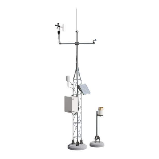
UT10. UT10 Tower Installation UT10 Tower Installation The UT10 3-meter tower provides a support structure for mounting the weather station components. FIGURE 2-1 shows a typical UT10 equipped with an instrumentation enclosure, meteorological sensors, and a solar panel. -
Page 15: Base Installation
UT10 Weather Station FIGURE 2-1. UT10 Weather Tower 2.1.1 Base Installation The UT10 tower attaches to a user-supplied concrete foundation as shown in FIGURE 2-1. The base brackets, anchor bolts, and nuts are included with the tower. 1. Dig a hole 24 in square and 24 in deep. Lighter soils will require a deeper hole. -
Page 16: J-Bolt Template Assembly
UT10 Weather Station each j-bolt so the angled portion is pointing outward and tighten the lower nuts to secure the assembly. 3. Construct a concrete form shown in FIGURE 2-3 out of 2 in x 4 in lumber 24 in square (inside dimensions). Construct the 1 in x 2 in template frame and set it aside. -
Page 17: Tower Installation
Tighten the two bolts to secure the mast. FIGURE 2-4. Install the UT10 mast. 2. Remove the three 5/16 in bolts, nuts, and fender washers from the UT10 mounting brace (FIGURE 2-5). 3. Pivot the three mounting feet to the vertical position. -
Page 18: Ut10 Mounting Brace Removal
5/16 in bolt FIGURE 2-5. UT10 Mounting Brace Removal 4. Align the UT10 so the openings in the mounting feet are running East- West. Align the hole in the bottom of each mounting foot with one of the j-bolts in the concrete base. Slide the UT10 onto the j-bolts. -
Page 19: Sensor Mounting Brackets
FIGURE 2-6. UT10 Mounting Foot Detail View 6. Check the UT10 for plumb using a level and adjust the leveling nuts below the mounting feet on the j-bolts as required. When the tower is plumb, use two wrenches to lock the lower nuts on each j-bolt together. Tighten the upper nuts to secure the base. -
Page 20: 019Alu Crossarm
UT10 Weather Station 2.2.1.2 019ALU Crossarm Attach the 019ALU crossarm to the mast as shown in FIGURE 2-9. 2. Position the middle NU-RAIL so that it rests on top of the bell reducer. Orient the 019ALU in a East/West direction, with the 3/4 in NU-RAIL facing East and tighten the set screws. -
Page 21: Cm225 Pyranometer Stand
UT10 Weather Station FIGURE 2-8. CM210 crossarm-to-pole bracket (top) is included with the crossarm for attaching the crossarm to the tower’s mast or leg. Lightning Rod 019ALU FIGURE 2-9. 019ALU Crossarm and Lightning Rod 2.2.3 CM225 Pyranometer Stand The CM225 Pyranometer stand is used to mount the LI200X, LI190SB, CS300, CMP3, and LP02 solar radiation sensors to either a tower leg, mast, or crossarm. -
Page 22: Cm225 Solar Radiation Mount With A Li2003S Leveling Base And Li200X Solar Radiation Sensor
UT10 Weather Station the LI2003S leveling base supports the LI200X and LI190SB probes (see FIGURE 2-10). Both leveling bases use a bubble level and three adjustable leveling screws to level the sensor. The CMP3 and LP02 pyranometers include their own bubble level and leveling screws allowing them to attach directly to the CM225. -
Page 23: Instrumentation Installation
The “-TM” option is used to attach our enclosures to a UT10 tower. An enclosure ordered with the “-TM” option will be shipped with a three-piece bracket mounted to the top of the enclosure and an identical three-piece bracket mounted to the bottom of the enclosure. -
Page 24: Enclosure Brackets Configured For A Tower Mount
FIGURE 3-1. Enclosure brackets configured for a tower mount. The default configuration is for attaching to a UT10 tower (i.e., D = 10.25 in). To attach to a UT20 or UT30 tower, move the flange sections of the bracket so that D = 17 in. -
Page 25: Datalogger And Power Supply
UT10 Weather Station FIGURE 3-3. An enclosure attached to two tower legs. 3.1.2 Datalogger and Power Supply The datalogger includes hardware for mounting it to an enclosure backplate (see FIGURE 3-4). Either a BPALK or PS100 power supply is also typically housed in the enclosure if a CR800, CR850, or CR1000 is used. -
Page 26: Solar Panel
4. Turn power switch to “ON”, and replace cover. 3.1.5 Solar Panel Solar panels purchased from Campbell Scientific are shipped with a charge plug taped to the back of the panel. The charge plug is not used with the PS100. Refer to the solar panel manual for installation instructions. -
Page 27: Cr1000 And Ps100 Mounted To An Enclosure Backplate
UT10 Weather Station FIGURE 3-4. CR1000 and PS100 Mounted to an Enclosure Backplate FIGURE 3-5. SP10 Solar Panel... -
Page 28: Sensor Connection
UT10 Weather Station Sensor Connection 1. After the sensors have been mounted, route the sensor leads through the entry hole in the bottom of the enclosure and to the datalogger. Secure the leads to the left side of the enclosure using cable ties and tabs (FIGURE 3-6). -
Page 29: Cfm100, Nl115, Or Nl120
UT10 Weather Station 3.3.1 CFM100, NL115, or NL120 Connect a CFM100, NL115, or NL120 module to the peripheral port of a CR1000 or CR3000 datalogger (see FIGURE 3-7). One CompactFlash card fits in the CFM100 or NL115’s card slot. For the NL115 or NL120, Ethernet communications is supported by connecting a 10baseT Ethernet cable. -
Page 30: Cellular Transceivers
FIGURE 3-8. COM220 Modem with Surge Protector 3.3.3 Cellular Transceivers Campbell Scientific offers two digital cellular modems—the RavenXTV CDMA modem and the RavenXTG GPRS modem. Refer to our product brochure for information on choosing the right cellular modem for your weather station. -
Page 31: Srm-5A Rad Modem And Sc932A Interface
UT10 Weather Station 3.3.4 SRM-5A Rad Modem and SC932A Interface Rad Modems enable communication between the datalogger and computer over 4-wire unconditioned telephone line, or cable with two twisted pairs of wires. The maximum distance between modems is determined by baud rate and wire gauge. -
Page 32: Srm-5A Rad Modem And Sc932A Interface
UT10 Weather Station 3. Route the cable from the remote SRM-5A, and the cable from the SRM- 5A attached to the computer to the 6361. Connect the cables as shown in FIGURE 3-11. Strain relief the cables using cable ties and tabs. -
Page 33: Srm-5A Wiring
UT10 Weather Station Datalogger Computer FIGURE 3-10. SRM-5A Wiring... -
Page 34: Rf500M Rf Modem And Rf310-Series Transceivers
Device Configuration Utility software is used to configure the RF500M modem. Device Configuration Utility is included with LoggerNet or it can be downloaded for free from the Campbell Scientific web site (http://www.campbellsci.com). The configuration options can be seen in the... -
Page 35: Rf500M Rf Base Station
UT10 Weather Station There are five configuration options for the RF500M 1. RF ID – Set the modem address with a value from 1-255. Each RF500M in the network must have a unique RF ID. 2. CS I/O Settings – Set the CS I/O interface options. Choose the SDC... -
Page 36: Install Nearest Repeater/Field Station
3.3.6 MD485 Multidrop Interface Campbell Scientific’s MD485 is an intelligent RS-485 interface that permits a PC to address and communicate with one or more dataloggers over a distance of 4000 ft. The distance between the datalogger and computer can be increased by combining it with a phone modem, Ethernet link, or spread spectrum radio. -
Page 37: Sealing And Desiccating The Enclosure
FIGURE 3-11. You can configure any two types of interface ports (RS-485, RS-232, and CS I/O) to be used at a time. Sealing and Desiccating the Enclosure Campbell Scientific enclosures include an Enclosure Supply Kit with the following items: (4) Desiccant packs... -
Page 38: Sensor Installation
UT10 Weather Station replaced with fresh packs when the upper dot on the indicator begins to turn pink. The indicator card does not need to be replaced unless the colored circles overrun. HUMIDITY INDICATOR MS20003-2 EXAMINE ITEM IF PINK CHANGE... -
Page 39: And 05305 Rm Young Wind Monitors
UT10 Weather Station FIGURE 4-1. Met One 034B Wind Speed and Direction Sensor 05103, 05103-45, 05106, and 05305 RM Young Wind Monitors Mount the Wind Monitor to the CM202, CM204, or CM206 crossarm as shown in FIGURE 4-2. 1. Attach the CM220 bracket on the crossarm via the U-bolt and nuts. -
Page 40: 03002 Rm Young Wind Sentry Wind Set
UT10 Weather Station FIGURE 4-2. 05103 RM Young Wind Monitor 03002 RM Young Wind Sentry Wind Set The 03002 can be mounted directly to the mast, or to the CM202, CM204, or CM206 Crossarm. 4.3.1 03002 Mounted to the Mast 1. -
Page 41: Licor Silicon Radiation Sensors (Li200X, Li200S, Li190Sb)
UT10 Weather Station FIGURE 4-3. 03002 Mounted to a CM200-series Crossarm Licor Silicon Radiation Sensors (LI200X, LI200S, LI190SB) Mount the Radiation Sensor to the LI2003S Base and Leveling Fixture as shown in FIGURE 4-4. 1. Position the base of the sensor in the mounting flange on the LI2003S, and tighten the set screw with the Allen wrench provided. -
Page 42: 107/108 Temperature Probe
UT10 Weather Station 107/108 Temperature Probe Mount the 107 temperature probe inside the 41303-5A 6-plate radiation shield as shown in FIGURE 4-5. 1. Loosen the two mounting clamp screws on the base of the radiation shield. Insert the 107 probe through the mounting clamp until the white heat shrink is even with the bottom of the clamp. -
Page 43: 107/108 Soil Temperature Probe
UT10 Weather Station 107/108 Soil Temperature Probe 1. Select an undisturbed area of ground on the side of the tower that will receive the least amount of traffic. Route the sensor lead from the datalogger to the selected area. 2. Dig a narrow trench next to the sensor lead, ending the trench at least 6 in short of the probe tip. -
Page 44: Hmp60 Temperature And Rh Probe
UT10 Weather Station HMP60 Mounting Clamp FIGURE 4-6. HMP60 Temperature and RH Probe... -
Page 45: Hc2S3 Rotronic Temperature And Rh Probe
UT10 Weather Station HC2S3 Rotronic Temperature and RH Probe Mount the probe inside the 41003-5 10-plate radiation shield as shown in FIGURE 4-7. 1. Insert the 27731 hex plug that ships with the HC2S3 probe into the underside of the 41003-5 base. -
Page 46: Cs100 Or Cs106 Barometric Pressure Sensor
UT10 Weather Station CS100 or CS106 Barometric Pressure Sensor Mount the CS100 or CS106 to the enclosure backplate. 1. Mount the barometer to the mounting plate using the two screws and grommets provided. 4.10 Texas Electronics Tipping Bucket Rain Gages (TE525, TE525WS, TE525MM) 1. -
Page 47: Tb4, Tb4Mm Or Cs700 Rain Gage
UT10 Weather Station 4.11 TB4, TB4MM or CS700 Rain Gage The rain gage should be mounted in a relatively level spot that is representative of the surrounding area. The lip of the funnel should be horizontal and at least 30 inches above the ground. The ground surface around the rain gage should be natural vegetation or gravel. -
Page 48: Sr50A Sonic Ranging Sensor
UT10 Weather Station 4.12 SR50A Sonic Ranging Sensor 4.12.1 Beam Angle When mounting the SR50A, the sensor’s beam angle needs to be considered (see FIGURE 4-10). It is always best to mount the SR50A perpendicular to the intended target surface. The SR50A has a beam angle of approximately 30 degrees. -
Page 49: Mounting Options
UT10 Weather Station the outer edge of the plastic transducer housing see FIGURE 4-11. If this edge is used, simply add 8mm to the measured distance. FIGURE 4-11. Distance from Edge of Transducer Housing to Grill 4.12.3 Mounting Options There are two standard mounting options available for the SR50A sensor. -
Page 50: The Sr50A Mounted To The Crossarm Shown From Another Angle
UT10 Weather Station FIGURE 4-13. The SR50A Mounted to the Crossarm Shown from Another Angle FIGURE 4-14. SR50A - Mounted using Nurail and C2151 Mounting Stem SR50A with 6-plate gill radiation shield – the picture below shows the SR50A stem attachment... -
Page 51: Cs616 Water Content Reflectometer
UT10 Weather Station 4.13 CS616 Water Content Reflectometer Probe rods can be inserted vertically or horizontally into the soil surface or buried at any orientation to the surface. A probe inserted vertically into a soil surface will give an indication of the water content in the upper 30 cm of soil. -
Page 52: 237 Leaf Wetness Sensor
UT10 Weather Station 4.14 237 Leaf Wetness Sensor Mounting and orientation considerations are left to the user to determine. Consult the 237 manual for preparation and other information. Normally, the sensor is mounted away from the meteorological tower in or near a plant canopy. -
Page 53: Cs210 Enclosure Humidity Sensor
UT10 Weather Station FIGURE 4-17. 257 Soil Moisture Sensor 4.16 CS210 Enclosure Humidity Sensor Mount the CS210 inside the environmental enclosure or onto a datalogger using the mounting block and the wire tie included with the sensor (FIGURE 4-18). ®... -
Page 54: Wind Direction Sensor Orientation
UT10 Weather Station 4.17 Wind Direction Sensor Orientation 4.17.1 Determining True North and Sensor Orientation Orientation of the wind direction sensor is done after the datalogger has been programmed, and the location of True North has been determined. True North is usually found by reading a magnetic compass and applying the correction for magnetic declination*;... -
Page 55: National Geophysical Data Center Web Site
UT10 Weather Station FIGURE 4-19. Magnetic Declination for the Contiguous United States 4.17.2 National Geophysical Data Center Web Site This web site facilitates the task of determining magnetic declination for your weather station. The web site uses longitude and latitude to determine declination. -
Page 56: Standard Software Installation
UT10 Weather Station FIGURE 4-20. Declination Angles East of True North are Subtracted from 0 to get True North FIGURE 4-21. Declination Angles West of True North are Added to 0 to get True North Standard Software Installation Software required for a weather station consists of the datalogger program and a datalogger support software suite for Windows. -
Page 57: Weather Station Or Datalogger Support Suite
5. Use the EZ Setup Wizard in VisualWeather, PC400, or LoggerNet to set up the weather station. Maintenance and Troubleshooting These guidelines apply to several different Campbell Scientific weather stations. Maintenance Proper maintenance of weather station components is essential to obtain accurate data. -
Page 58: Batteries
RH inside the enclosure. Change the desiccant when either the card or the sensor read about 35% RH. Desiccant may be ordered through Campbell Scientific (pn 6714). Desiccant packs inside of the dataloggers do not require replacement under normal conditions. -
Page 59: Troubleshooting
UT10 Weather Station General Maintenance • An occasional cleaning of the glass on the solar panel will improve its efficiency. • Check sensor leads and cables for cracking, deterioration, proper routing, and strain relief. • Check the tripod or tower for structural damage, proper alignment, and for level/plumb. -
Page 60: No Response From Datalogger Through Sc32B Or Modem Peripheral
D. Make sure the Station File is configured correctly (LoggerNet or PC400 Manual). Check the cable(s) between the serial port and the modem. If cables have not been purchased through Campbell Scientific, check for the following configuration using an ohm meter: 25-pin serial port:... -
Page 61: Unreasonable Results Displayed In A Variable
UT10 Weather Station 6.2.4 Unreasonable Results Displayed in a Variable A. Inspect the sensor for damage and/or contamination. Make sure the sensor is properly wired to the datalogger. Check the multiplier and offset parameters in the measurement instruction. - Page 62 UT10 Weather Station...
- Page 64 Campbell Scientific Ltd. (CSL Germany) Fahrenheitstraße 13 28359 Bremen GERMANY www.campbellsci.de • info@campbellsci.de Campbell Scientific Spain, S. L. (CSL Spain) Avda. Pompeu Fabra 7-9, local 1 08024 Barcelona SPAIN www.campbellsci.es • info@campbellsci.es Please visit www.campbellsci.com to obtain contact information for your local US or international representative.
Need help?
Do you have a question about the UT10 and is the answer not in the manual?
Questions and answers