Campbell UT10 Instruction Manual
Universal tower
Hide thumbs
Also See for UT10:
- Insrtuction manual (64 pages) ,
- Product manual (29 pages) ,
- Product manual (32 pages)

Subscribe to Our Youtube Channel
Related Manuals for Campbell UT10


Summary of Contents for Campbell UT10
- Page 1 UT10 Universal Tower Revision: 6/16 C o p y r i g h t © 1 9 9 3 - 2 0 1 6 C a m p b e l l S c i e n t i f i c ,...
- Page 3 Limited Warranty “Products manufactured by CSI are warranted by CSI to be free from defects in materials and workmanship under normal use and service for twelve months from the date of shipment unless otherwise specified in the corresponding product manual. (Product manuals are available for review online at www.campbellsci.com.) Products not manufactured by CSI, but that are resold by CSI, are warranted only to the limits extended by the original manufacturer.
- Page 4 SCIENTIFIC, INC., phone (435) 227-9000. After an application engineer determines the nature of the problem, an RMA number will be issued. Please write this number clearly on the outside of the shipping container. Campbell Scientific’s shipping address is: CAMPBELL SCIENTIFIC, INC.
- Page 5 • Periodically (at least yearly) check electrical ground connections. WHILE EVERY ATTEMPT IS MADE TO EMBODY THE HIGHEST DEGREE OF SAFETY IN ALL CAMPBELL SCIENTIFIC PRODUCTS, THE CUSTOMER ASSUMES ALL RISK FROM ANY INJURY RESULTING FROM IMPROPER INSTALLATION, USE, OR MAINTENANCE OF TRIPODS, TOWERS, OR ATTACHMENTS TO TRIPODS AND TOWERS SUCH AS SENSORS, CROSSARMS, ENCLOSURES, ANTENNAS, ETC.
-
Page 7: Table Of Contents
Solar Radiation ..................5 Soil Temperature .................. 5 Siting References ................. 5 5. Overview ..............6 6. Specifications ............. 7 7. UT10 Tower Installation ..........7 Installing the UT10 ................7 7.1.1 Base Installation ................8 7.1.2 Tower Installation ............... 10 Sensor Mounting Brackets .............. - Page 8 Table of Contents Communication and Data Storage Peripherals ........22 8.3.1 CFM100, NL115, or NL120 ............22 8.3.2 COM220 Phone Modems ............22 8.3.3 Cellular Transceivers ..............23 8.3.4 SRM-5A Rad Modem and SC932A Interface ......24 8.3.4.1 SRM-5A at the Datalogger ..........24 8.3.4.2 SRM-5A at the Computer ..........
- Page 9 7-4. Install the UT10 mast ................. 10 7-5. UT10 mounting brace removal ............11 7-6. UT10 mounting foot detail view ............12 7-7. Top view of tower ................13 7-8. CM210 crossarm-to-pole bracket (top) is included with the crossarm for attaching the crossarm to the tower’s mast or leg ..14 7-9.
- Page 10 Table of Contents 8-24. TB4 or TB4MM mounted onto a CM310 Pole via the CM240 Mount ..................... 43 8-25. Beam angle clearance ................ 44 8-26. Distance from edge of transducer housing to grill......45 8-27. SR50A mounted to a crossarm via the 19517 Mounting Kit ..... 45 8-28.
-
Page 11: Introduction
UT10 Universal Tower Introduction The UT10 is a durable, lightweight instrument tower that can be used for a variety of applications. It supports a 3 m (10 ft) measurement height for wind sensors as well as sturdy attachment points for antennas, solar panels, environmental enclosures, radiation shields, and crossarms. -
Page 12: Outdoors
• Locate suitable site (Section 4, Siting and Exposure (p. 3) • Prepare tower base (Section 7, UT10 Tower Installation (p. 7) Raise tower (Section 7, UT10 Tower Installation (p. 7) Install instrumentation enclosure (Section 8, Preparing the Tower for (p. -
Page 13: Supplies For Power And Communications Options
UT10 Universal Tower Step ladder (6 ft) Station manuals Station log and pen Open end wrenches: 3/8 in, 7/16 in, 1/2 in, (2) 9/16 in Socket wrench and 7/16 in deep well socket Adjustable wrench Pliers Conduit and associated tools (as required) -
Page 14: Temperature And Relative Humidity
UT10 Universal Tower Standard measurement heights: 3.0 m ± 0.1 m recommended (AASC) 2.0 m ± 0.1 m, 10.0 m ± 0.5 m optional (AASC) 10.0 m (WMO and EPA) Temperature and Relative Humidity Sensors should be located over an open level area at least 9 m (EPA) in diameter. -
Page 15: Solar Radiation
UT10 Universal Tower Solar Radiation Pyranometers should be located to avoid shadows on the sensor at any time. Mounting it on the southernmost (northern hemisphere) portion of the weather station will minimize the chance of shading from other weather station structures. -
Page 16: Overview
Systems, EPA Office of Research and Development, Research Triangle Park, North Carolina 27711. Overview The UT10 tower is a versatile mount for sensors, antennas, solar panels, environmental enclosures, radiation shields, and mounting crossarms. Its 3 m (10 ft) height allows for wind measurements at that height. -
Page 17: Specifications
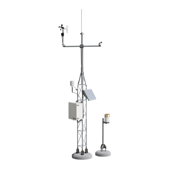
UT10. UT10 Tower Installation Installing the UT10 The UT10 3-meter tower provides a support structure for mounting the weather station components. FIGURE shows a typical UT10 equipped with an instrumentation enclosure, meteorological sensors, and a solar panel. -
Page 18: Base Installation
UT10 Universal Tower FIGURE 7-1. UT10 weather tower 7.1.1 Base Installation The UT10 tower attaches to a user-supplied concrete foundation as shown in FIGURE 7-1. The base brackets, anchor bolts, and nuts are included with the tower. Dig a hole 24 inches square and 24 inches deep. Lighter soils will require a deeper hole. -
Page 19: J-Bolt Template Assembly
UT10 Universal Tower Construct a concrete form shown in FIGURE out of 2-inch x 4-inch lumber 24 inches square (inside dimensions). Construct the 1-inch x 2-inch template frame and set it aside. Center the form over the hole and drive a stake centered along the outside edge of each side. -
Page 20: Tower Installation
Tighten the two bolts to secure the mast. FIGURE 7-4. Install the UT10 mast Remove the three 5/16-inch bolts, nuts, and fender washers from the UT10 mounting brace (FIGURE 7-5). Pivot the three mounting feet to the vertical position. -
Page 21: Ut10 Mounting Brace Removal
UT10 Universal Tower FIGURE 7-5. UT10 mounting brace removal Align the UT10 so the openings in the mounting feet are angled diagonally away at a 60° angle. This allows a solar panel to be mounted across the two tower legs facing the equator while allowing the tower to tilt away from the equator for servicing. -
Page 22: Sensor Mounting Brackets
J-bolt. Do not tighten the nut (FIGURE 7-6). FIGURE 7-6. UT10 mounting foot detail view Check the UT10 for plumb using a level and adjust the leveling nuts below the mounting feet on the J-bolts as required. When the tower is plumb, use two wrenches to lock the lower nuts on each J-bolt together. -
Page 23: Crossarm Mounting
UT10 Universal Tower 7.2.1 Crossarm Mounting 7.2.1.1 CM202, CM203, CM204, CM206 Crossarms Attach the crossarm at the desired height via the provided U-bolts and nuts (FIGURE 7-8). 7.2.1.2 019ALU Crossarm Attach the 019ALU crossarm to the mast as shown in FIGURE 7-9. -
Page 24: Cm225 Pyranometer Stand
UT10 Universal Tower FIGURE 7-8. CM210 crossarm-to-pole bracket (top) is included with the crossarm for attaching the crossarm to the tower’s mast or leg Lightning Rod 019ALU FIGURE 7-9. 019ALU crossarm and lightning rod 7.2.3 CM225 Pyranometer Stand The CM225 pyranometer stand is used to mount the LI200X, LI190SB, CS300, CMP3, and LP02 solar radiation sensors to either a tower leg, mast, or crossarm. -
Page 25: Cm225 Solar Radiation Mount With A Li2003S Leveling Base And Li200X Solar Radiation Sensor
UT10 Universal Tower the LI2003S leveling base supports the LI200X and LI190SB probes (see FIGURE 7-10). Both leveling bases use a bubble level and three adjustable leveling screws to level the sensor. The CMP3 and LP02 pyranometers include their own bubble level and leveling screws allowing them to attach directly to the CM225. -
Page 26: Preparing The Tower For Use
The “-TM” option is used to attach our enclosures to a UT10 tower. An enclosure ordered with the “-TM” option will be shipped with a three-piece bracket mounted to the top of the enclosure and an identical three-piece bracket mounted to the bottom of the enclosure. -
Page 27: Enclosure Brackets Configured For A Tower Mount
UT10 Universal Tower FIGURE 8-1. Enclosure brackets configured for a tower mount The default configuration is for attaching to a UT10 tower (for example, D = 10.25 in). To attach to a UT20 or UT30 tower, move the flange sections of the bracket so that D = 17 in. -
Page 28: Datalogger And Power Supply
UT10 Universal Tower FIGURE 8-3. An enclosure attached to two tower legs 8.1.2 Datalogger and Power Supply The datalogger includes hardware for mounting it to an enclosure backplate (see FIGURE 8-4). Either a BPALK or PS100 power supply is also typically housed in the enclosure if a CR800, CR850, or CR1000 is used. -
Page 29: Solar Panel
Turn power switch to “ON”, and replace cover. 8.1.5 Solar Panel Solar panels purchased from Campbell Scientific are shipped with a charge plug taped to the back of the panel. The charge plug is not used with the PS100. Refer to the solar panel manual for installation instructions. -
Page 30: Cr1000 And Ps100 Mounted To An Enclosure Backplate
UT10 Universal Tower FIGURE 8-4. CR1000 and PS100 mounted to an enclosure backplate FIGURE 8-5. SP10 Solar Panel... -
Page 31: Sensor Connection
UT10 Universal Tower Sensor Connection After the sensors have been mounted, route the sensor leads through the entry hole in the bottom of the enclosure and to the datalogger. Secure the leads to the left side of the enclosure using cable ties and tabs (FIGURE 8-6). -
Page 32: Communication And Data Storage Peripherals
UT10 Universal Tower Communication and Data Storage Peripherals One or more peripherals (for example, CompactFlash modules, modems, etc.) can be mounted to the enclosure backplate (ENC12/14, ENC14/16, or ENC16/18 enclosures). 8.3.1 CFM100, NL115, or NL120 Connect a CFM100, NL115, or NL120 module to the peripheral port of a CR1000 or CR3000 datalogger (see FIGURE 8-7). -
Page 33: Cellular Transceivers
FIGURE 8-8. COM220 Modem with surge protector 8.3.3 Cellular Transceivers Campbell Scientific offers two digital cellular modems — the RavenXTV CDMA modem and the RavenXTG GPRS modem. Refer to our product brochure for information on choosing the right cellular modem for your weather station. -
Page 34: Srm-5A Rad Modem And Sc932A Interface
UT10 Universal Tower 8.3.4 SRM-5A Rad Modem and SC932A Interface Rad Modems enable communication between the datalogger and the computer over 4-wire unconditioned telephone line, or cable with two twisted pairs of wires. The maximum distance between modems is determined by baud rate and wire gauge. -
Page 35: Srm-5A Rad Modem And Sc932A Interface
UT10 Universal Tower FIGURE 8-9. SRM-5A Rad Modem and SC932A Interface... -
Page 36: Srm-5A Wiring
UT10 Universal Tower Datalogger Computer FIGURE 8-10. SRM-5A wiring... -
Page 37: Rf500M Rf Modem And Rf310-Series Transceivers
Device Configuration Utility software is used to configure the RF500M modem. Device Configuration Utility is included with LoggerNet or it can be downloaded for free from the Campbell Scientific website (http://www.campbellsci.com). The configuration options can be seen in the following figure:... -
Page 38: Rf500M Rf Base Station
UT10 Universal Tower There are five configuration options for the RF500M: 1. RF ID – Set the modem address with a value from 1–255. Each RF500M in the network must have a unique RF ID. 2. CS I/O Settings – Set the CS I/O interface options. Choose the SDC... -
Page 39: Install Nearest Repeater/Field Station
8.3.6 MD485 Multidrop Interface Campbell Scientific’s MD485 is an intelligent RS-485 interface that permits a PC to address and communicate with one or more dataloggers over a distance of 4000 ft. The distance between the datalogger and computer can be increased by combining it with a phone modem, Ethernet link, or spread spectrum radio. -
Page 40: Sealing And Desiccating The Enclosure
FIGURE 8-11. You can configure any two types of interface ports (RS-485, RS-232, and CS I/O) to be used at a time Sealing and Desiccating the Enclosure Campbell Scientific enclosures include an enclosure supply kit with the following items: (4) Desiccant packs... -
Page 41: Sensor Installation
8.5.1.1 Overview The CMB200 Crossarm Brace Kit (FIGURE 8-13) is designed to provide additional stability to crossarms mounted on Campbell Scientific tripods and towers. It provides additional support for crossarms with heavier sensor loads, and added stability in high winds. -
Page 42: Components
UT10 Universal Tower Short Tab Long Tab FIGURE 8-13. CMB200 Crossarm Brace Kit 8.5.1.2 Components The CMB200 ships with the following components (FIGURE 8-14): • (1) Brace Arm • (2) Small bracket • (2) Medium bracket • (2) Large bracket •... -
Page 43: Assembly
UT10 Universal Tower 8.5.1.3 Assembly Consult FIGURE 8-15 and TABLE to determine which brackets are needed at either end of the brace to attach it to the crossarm and tripod mast or tower. The figure also indicates what orientation is needed when the small bracket is used. -
Page 44: Bracket Selection
UT20/30) CM202/3/4/6 Crossarm, UT20/30 Tower Mast, (1) Small Bracket Angled away from Ø1.25 in or Ø1.31 in UT20/30 Tower Leg (1) Medium Bracket mast/tripod (bottom section only) CM110/106B Tripod Ø1.90 in (2) Large Bracket Mast, UT10 Tower Mast... -
Page 45: 034B Met One Windset
UT10 Universal Tower 8.5.2 034B Met One Windset Mount the 034B to the CM202, CM204, or CM206 crossarm as shown in FIGURE 8-16. Mount the CM220 bracket on the crossarm via the U-bolt and nuts. Place the 034B stem and bushing into the CM220 bracket. -
Page 46: 03002 Rm Young Wind Sentry Wind Set
UT10 Universal Tower FIGURE 8-17. 05103 RM Young Wind Monitor 8.5.4 03002 RM Young Wind Sentry Wind Set The 03002 can be mounted directly to the mast, or to the CM202, CM204, or CM206 Crossarm. 8.5.4.1 03002 Mounted to the Mast Slide the crossarm mounting bracket onto the mast. -
Page 47: Licor Silicon Radiation Sensors (Li200X, Li200S, Li190Sb)
UT10 Universal Tower FIGURE 8-18. 03002 mounted to a CM200-series Crossarm 8.5.5 Licor Silicon Radiation Sensors (LI200X, LI200S, LI190SB) Mount the Radiation Sensor to the LI2003S Base and Leveling Fixture as shown in FIGURE 8-19. Position the base of the sensor in the mounting flange on the LI2003S, and tighten the set screw with the Allen wrench provided. -
Page 48: 107/108 Temperature Probe
UT10 Universal Tower 8.5.6 107/108 Temperature Probe Mount the 107 temperature probe inside the 41303-5A 6-plate radiation shield as shown in FIGURE 8-20. Loosen the two mounting clamp screws on the base of the radiation shield. Insert the 107 probe through the mounting clamp until the white heat shrink is even with the bottom of the clamp. -
Page 49: 107/108 Soil Temperature Probe
UT10 Universal Tower 8.5.7 107/108 Soil Temperature Probe Select an undisturbed area of ground on the side of the tower that will receive the least amount of traffic. Route the sensor lead from the datalogger to the selected area. Dig a narrow trench next to the sensor lead, ending the trench at least 6 in short of the probe tip. -
Page 50: Hmp60 Temperature And Rh Probe
UT10 Universal Tower HMP60 Mounting Clamp FIGURE 8-21. HMP60 Temperature and RH Probe... -
Page 51: Hc2S3 Rotronic Temperature And Rh Probe
UT10 Universal Tower 8.5.9 HC2S3 Rotronic Temperature and RH Probe Mount the probe inside the 41003-5 10-plate radiation shield as shown in FIGURE 8-22. Insert the 27731 hex plug that ships with the HC2S3 probe into the underside of the 41003-5 base. -
Page 52: Cs100 Or Cs106 Barometric Pressure Sensor
UT10 Universal Tower 8.5.10 CS100 or CS106 Barometric Pressure Sensor Mount the CS100 or CS106 to the enclosure backplate. Mount the barometer to the mounting plate using the two screws and grommets provided. 8.5.11 Texas Electronics Tipping Bucket Rain Gages (TE525, TE525WS,... -
Page 53: Tb4, Tb4Mm Or Cs700 Rain Gage
UT10 Universal Tower 8.5.12 TB4, TB4MM or CS700 Rain Gage The rain gage should be mounted in a relatively level spot that is representative of the surrounding area. The lip of the funnel should be horizontal and at least 30 inches above the ground. The ground surface around the rain gage should be natural vegetation or gravel. -
Page 54: Sr50A Sonic Ranging Sensor
UT10 Universal Tower 8.5.13 SR50A Sonic Ranging Sensor 8.5.13.1 Beam Angle When mounting the SR50A, the sensor’s beam angle needs to be considered (see FIGURE 8-25). It is always best to mount the SR50A perpendicular to the intended target surface. The SR50A has a beam angle of approximately 30 degrees. -
Page 55: Mounting Options
UT10 Universal Tower FIGURE 8-26. Distance from edge of transducer housing to grill 8.5.13.3 Mounting Options There are two standard mounting options available for the SR50A sensor. The first is the SR50A Mounting Kit, part number 19517. This bracket is used to mount the SR50A to a CM206 crossarm or a pipe with a 1 in to 1.75 in OD. - Page 56 UT10 Universal Tower FIGURE 8-28. The SR50A mounted to the crossarm shown from another angle FIGURE 8-29. SR50A - Mounted using NU-RAIL and C2151 Mounting Stem SR50A with 6-plate radiation shield – the picture below shows the SR50A stem attachment...
-
Page 57: Cs616 Water Content Reflectometer
UT10 Universal Tower 8.5.14 CS616 Water Content Reflectometer Probe rods can be inserted vertically or horizontally into the soil surface or buried at any orientation to the surface. A probe inserted vertically into a soil surface will give an indication of the water content in the upper 30 cm of soil. -
Page 58: 237 Leaf Wetness Sensor
UT10 Universal Tower 8.5.15 237 Leaf Wetness Sensor Mounting and orientation considerations are left to the user to determine. Consult the 237 manual for preparation and other information. Normally, the sensor is mounted away from the meteorological tower in or near a plant canopy. -
Page 59: Cs210 Enclosure Humidity Sensor
UT10 Universal Tower FIGURE 8-32. 257 Soil Moisture Sensor 8.5.17 CS210 Enclosure Humidity Sensor Mount the CS210 inside the environmental enclosure or onto a datalogger using the mounting block and the wire tie included with the sensor (FIGURE 8-33). ®... -
Page 60: Wind Direction Sensor Orientation
UT10 Universal Tower 8.5.18 Wind Direction Sensor Orientation 8.5.18.1 Determining True North and Sensor Orientation Orientation of the wind direction sensor is done after the datalogger has been programmed, and the location of True North has been determined. True North is usually found by reading a magnetic compass and applying the correction for magnetic declination*;... -
Page 61: National Geophysical Data Center Website
UT10 Universal Tower FIGURE 8-34. Magnetic declination for the contiguous United States 8.5.18.2 National Geophysical Data Center Website This website facilitates the task of determining magnetic declination for your weather station. The website uses longitude and latitude to determine declination. Customers located in the U.S. can find their site’s longitude and latitude. -
Page 62: Maintenance And Troubleshooting
FIGURE 8-36. Declination angles west of True North are Added to 0 to get True North Maintenance and Troubleshooting These guidelines apply to several different Campbell Scientific weather stations. Maintenance Proper maintenance of weather station components is essential to obtain accurate data. -
Page 63: Instrumentation Maintenance
RH inside the enclosure. Change the desiccant when either the card or the sensor read about 35% RH. Desiccant may be ordered through Campbell Scientific (pn 6714). Desiccant packs inside of the dataloggers do not require replacement under normal conditions. -
Page 64: Troubleshooting
UT10 Universal Tower 1 month • Check the rain gage funnel for debris and level. • Do a visual/audio inspection of the anemometer at low wind speeds. • Check the filter of the temperature/humidity sensor for contamination. General Maintenance •... -
Page 65: No Response From Datalogger Through Sc32B Or Modem Peripheral
Make sure the Station File is configured correctly (LoggerNet or PC400 Manual). Check the cable(s) between the serial port and the modem. If cables have not been purchased through Campbell Scientific, check for the following configuration using an ohm meter: 25-pin serial port:... -
Page 66: Nan Displayed In A Variable
UT10 Universal Tower 9.2.3 NaN Displayed in a Variable Make sure the battery voltage is between 9.6 and 16 Vdc. Verify the sensor is wired to the analog channel specified in the measurement instruction or Short Cut .FSL file (single-ended channels are not labeled on the older CR10 silver-colored wiring panels and are numbered sequentially starting at 1H;... - Page 67 UT10 Universal Tower Print the wiring diagram produced by Short Cut and follow the wiring assignments when connecting sensors to the weather station datalogger. Use the EZ Setup Wizard in VisualWeather, PC400, or LoggerNet to set up the weather station.
- Page 68 UT10 Universal Tower...
- Page 70 Santo Domingo, Heredia 40305 SOUTH AFRICA COSTA RICA • cleroux@csafrica.co.za • info@campbellsci.cc www.campbellsci.co.za www.campbellsci.cc Campbell Scientific Southeast Asia Co., Ltd. Campbell Scientific Ltd. 877/22 Nirvana@Work, Rama 9 Road Campbell Park Suan Luang Subdistrict, Suan Luang District 80 Hathern Road Bangkok 10250...
Need help?
Do you have a question about the UT10 and is the answer not in the manual?
Questions and answers