Table of Contents
Advertisement
Quick Links
Advertisement
Table of Contents

Subscribe to Our Youtube Channel
Related Manuals for Campbell UT6


Summary of Contents for Campbell UT6
- Page 1 Revision: 11/2020 Copyright © 1993 – 2020 Campbell Scientific, Inc.
-
Page 2: Table Of Contents
Table of contents 1. Introduction 2. Precautions 2.1 Site selection 2.2 Tower mounting 2.3 Tower installation 3. Initial inspection 3.1 Indoors 3.2 Outdoors 3.3 Tools required 4. Siting and exposure 4.1 Wind speed and direction 4.2 Temperature and relative humidity 4.3 Precipitation 4.4 Solar radiation 4.5 Soil temperature... -
Page 3: Introduction
1. Introduction The UT6 and UT10 are durable, lightweight instrument towers used for a variety of applications. They support a 1.8 m (6 ft) or 3 m (10 ft) measurement height for wind sensors as well as sturdy attachment points for antennas, solar panels, environmental enclosures, radiation shields, and crossarms. -
Page 4: Tower Installation
Inspect the shipping cartons for visible damage. Report any damage to the shipping company. Open all shipping cartons. Check the contents of the cartons against the invoice. Contact Campbell Scientific immediately if any parts are missing. 3.2 Outdoors Locate a suitable site for the tower (Siting and exposure (p. -
Page 5: Tools Required
Install the instrumentation enclosure (Tower installation (p. 9)). Install sensors. 3.3 Tools required Tools required to install and maintain a Campbell Scientific tower: Shovel Rake Open end wrenches: 3/8 in, 7/16 in, 1/2 in, (2) 9/16 in Socket wrench set... -
Page 6: Wind Speed And Direction
) from paved areas. Sensors must be protected from thermal radiation and adequately ventilated. Situations to avoid include: Industrial heat sources Rooftops Steep slopes Sheltered hollows Tall vegetation Shaded areas Swamps Areas where snow drifts occur Low places holding standing water after rainstorms UT6 and UT10 Universal Towers... -
Page 7: Precipitation
Reflective surfaces and sources of artificial radiation must be avoided. Heated pyranometers, such as the SP230-L from Campbell Scientific, are available for use in areas where snow, frost, or dew may accumulate. -
Page 8: Siting References
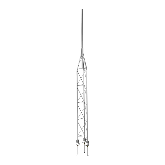
The UT6 and UT10 towers provide a versatile mount for sensors, antennas, solar panels, environmental enclosures, radiation shields, and mounting crossarms. The 2m (6 ft) height of the UT6 and 3m (10 ft) height of the UT10 allows for wind measurements at each height. The main tower frame (FIGURE 5-1 (p. - Page 9 FIGURE 5-1. UT6 and UT10 towers UT6 and UT10 Universal Towers...
-
Page 10: Specifications
2 square feet. The amount of wind load that this mount can withstand is affected by the quality of anchoring and installation, soil type, and the number, type, and location of instruments fastened to the tower. UT6 and UT10 Universal Towers... -
Page 11: Tower Installation
The tower provides a support structure for mounting the weather station components. FIGURE 7- (p. 9) shows a typical tower equipped with an instrumentation enclosure, meteorological sensors, and a solar panel. FIGURE 7-1. Weather tower UT6 and UT10 Universal Towers... -
Page 12: Base Installation
Once all three J-bolts are assembled, slide them together as shown in FIGURE 7-2 10). Align each J-bolt so the angled portion is pointing outward and tighten the lower nuts to secure the assembly. FIGURE 7-2. J-bolt template assembly UT6 and UT10 Universal Towers... - Page 13 Center the form over the hole and drive a stake at both ends of each 1.1 m (42 in) piece of the form. Level the form by driving nails through the stakes and into the form while holding the form level. FIGURE 7-3. Positioning the J-bolt in concrete UT6 and UT10 Universal Towers...
- Page 14 J-bolt to ensure proper anchoring. 6. Remove the top nuts, washers, and J-bolt template pieces. Leave the two bottom nuts and one flat washer on each J-bolt. Remove the template frame and the concrete form. UT6 and UT10 Universal Towers...
-
Page 15: Tower Installation
Loosen the two mast mounting bolts at the top of the tower and insert the mast. For the UT6 at a 1.8 m mounting height, or the UT10 at 3 m, rest the bell reducer against the top of the tower. Tighten the two bolts to secure the mast. - Page 16 3. Pivot the three mounting feet to the vertical position. FIGURE 7-6. Tower mounting brace removal UT6 and UT10 Universal Towers...
- Page 17 FIGURE 7-7. Mounting feet orientation Align the hole in the bottom of each mounting foot with one of the J-bolts in the concrete base. Slide the tower onto the J-bolts. UT6 and UT10 Universal Towers...
- Page 18 5. Place a 5/8-inch flat washer, a 5/8-inch split washer, and a 5/8-inch nut on each J-bolt. Do not tighten the nut (FIGURE 7-8 (p. 16)). FIGURE 7-8. Tower mounting foot detail view UT6 and UT10 Universal Towers...
-
Page 19: Ground Rod
Refer to the Safety section at the end of this manual prior to installing the ground rod. Ensure all local electrical codes are followed by having electrical equipment and grounding installed by a licensed electrician. UT6 and UT10 Universal Towers... - Page 20 2. Loosen the bolt that attaches the clamp to the ground rod. Insert one end of the 4 AWG wire between the rod and the clamp and tighten the bolt (FIGURE 7-9 (p. 18)). FIGURE 7-9. Ground rod and clamp UT6 and UT10 Universal Towers...
- Page 21 4 AWG wire and the 12 AWG enclosure ground wire into the hole behind the set screw and tighten the set screw. Route the green wire to where the enclosure will be installed. FIGURE 7-10. Tower grounding clamp UT6 and UT10 Universal Towers...
-
Page 22: Attaching The Lightning Rod
Mounting sensors on a crossarm allows the sensor to be moved away from the midline of the tower, reducing the effects of the mount on the sensor measurement. Campbell Scientific provides a variety of lengths in aluminum or stainless steel. Table 7-1 (p. 21) shows the different lengths available. - Page 23 1.2 m (4 ft) IPS anodized aluminum CM204SS 1.2 m (4 ft) Stainless-steel CM206 1.8 m (6 ft) IPS anodized aluminum FIGURE 7-12 (p. 21) shows two typical applications of a mounting bracket. FIGURE 7-12. Crossarm mounting UT6 and UT10 Universal Towers...
-
Page 24: Cmb200 Crossarm Brace Kit
(FIGURE 7-13 (p. 22)) is designed to provide additional stability to crossarms mounted on Campbell Scientific tripods and towers. It provides additional support for crossarms with heavier sensor loads, and added stability in high winds. FIGURE 7-13. CMB200 Crossarm Brace Kit... -
Page 25: Components
2. Attach one end of the brace arm to the tower below the crossarm. Leave the bolts finger- tight. 3. Lift the free end of the brace arm to the crossarm and attach it to the crossarm. Again, only finger-tighten the bolts. 4. Adjust the position of the brace arm as needed. UT6 and UT10 Universal Towers... - Page 26 5. Fully tighten the two bolts directly connected to the brace arm, and then tighten the remaining two bolts to clamp the brace arm to the tower. FIGURE 7-15. Bracket selection UT6 and UT10 Universal Towers...
-
Page 27: Cm230, Cm230Xl Adjustable Angle Mounting Kits
3.81 cm (1.0 in to 1.5 in). The bracket can be attached to a mast or pipe with an outer diameter of 3.30 cm to 5.33 cm (1.3 in to 2.1 in). The declination of the antenna or sensor is fixed when the U- UT6 and UT10 Universal Towers... - Page 28 (p. 26) is an exploded diagram of the CM230XL showing all the included hardware as well as the curved slots at the end of the bracket used to adjust the angle of the antenna or sensor. FIGURE 7-17. CM230XL exploded diagram UT6 and UT10 Universal Towers...
- Page 29 See Product Details on the Ordering Information pages at www.campbellsci.com. Other manufacturer's products, that are resold by Campbell Scientific, are warranted only to the limits extended by the original manufacturer.
- Page 30 Campbell Scientific office serves your country. To obtain a Returned Materials Authorization or Repair Reference number, contact your CAMPBELL SCIENTIFIC regional office. Please write the issued number clearly on the outside of the shipping container and ship as directed.
- Page 31 Do not recharge, disassemble, heat above 100 °C (212 °F), solder directly to the cell, incinerate, or expose contents to water. Dispose of spent batteries properly. WHILE EVERY ATTEMPT IS MADE TO EMBODY THE HIGHEST DEGREE OF SAFETY IN ALL CAMPBELL SCIENTIFIC PRODUCTS, THE CUSTOMER ASSUMES ALL RISK FROM ANY INJURY RESULTING FROM IMPROPER INSTALLATION, USE, OR MAINTENANCE OF TRIPODS, TOWERS, OR...
- Page 32 Campbell Scientific regional offices Australia France Thailand Location: Garbutt, QLD Australia Location: Vincennes, France Location: Bangkok, Thailand Phone: 61.7.4401.7700 Phone: 0033.0.1.56.45.15.20 Phone: 66.2.719.3399 Email: info@campbellsci.com.au Email: info@campbellsci.fr Email: info@campbellsci.asia Website: www.campbellsci.com.au Website: www.campbellsci.fr Website: www.campbellsci.asia Brazil Germany Location: São Paulo, SP Brazil...
Need help?
Do you have a question about the UT6 and is the answer not in the manual?
Questions and answers