
Subscribe to Our Youtube Channel
Related Manuals for Campbell RAWS-P


Summary of Contents for Campbell RAWS-P
- Page 1 RAWS-P Remote Automated Weather Station Revision: 12/13 C o p y r i g h t © 2 0 0 6 - 2 0 1 3 C a m p b e l l S c i e n t i f i c ,...
- Page 3 Campbell pricelist or product manual. Products not manufactured, but that are re-sold by Campbell, are warranted only to the limits extended by the original manufacturer. Batteries, fine-wire thermocouples, desiccant, and other consumables have no warranty.
- Page 4 SCIENTIFIC, INC., phone (435) 227-9000. After an application engineer determines the nature of the problem, an RMA number will be issued. Please write this number clearly on the outside of the shipping container. Campbell Scientific’s shipping address is: CAMPBELL SCIENTIFIC, INC.
-
Page 5: Table Of Contents
Table of Contents PDF viewers: These page numbers refer to the printed version of this document. Use the PDF reader bookmarks tab for links to specific sections. 1. Introduction ..............1 2. Getting Started ............2 3. Station Siting and Orientation ........5 General Description ................5 Air Temperature and Relative Humidity..........5 Precipitation ..................6... - Page 6 Table of Contents 5. Equipment Wiring and Troubleshooting....12 Solar Panels ..................12 5.1.1 General Description..............12 5.1.2 Wiring ..................13 5.1.3 Troubleshooting ................. 13 Charger/Regulator ................13 5.2.1 General Description..............13 5.2.2 Wiring ..................14 5.2.3 Troubleshooting ................. 15 Battery ....................15 5.3.1 General Description..............
- Page 7 Table of Contents Tables 2-1. Public Variables ...................4 4-1. TEMP/RH Connector (color coded orange).........7 4-2. PRECIP Connector (color coded blue) ..........7 4-3. SOLAR RAD SDI-12 Connector (color coded green)......8 4-4. WS/WD Connector (color coded red) ..........9 4-5. SDI-12 Connector (color coded yellow) ..........10 4-6.
- Page 8 Table of Contents...
-
Page 9: Introduction
RAWS-P Remote Automated Weather Station Introduction The RAWS-P is the core of a permanent station. It consists of a CR1000 datalogger and 12 Vdc battery, housed and protected in an aluminum environmental enclosure. The sensors and the tripod/tower are purchased separately—allowing you to customize your station exactly the way you want... -
Page 10: Getting Started
RAWS-P Remote Automated Weather Station Specifications are available from our web site at www.campbellsci.com. For “sensors specifications,” click on “Products”, select “Sensors” and go to the sensor manual for specifications. For “equipment specifications”, enter the part number in the “Search” box on the website mentioned above and go to the equipment manual for specifications. -
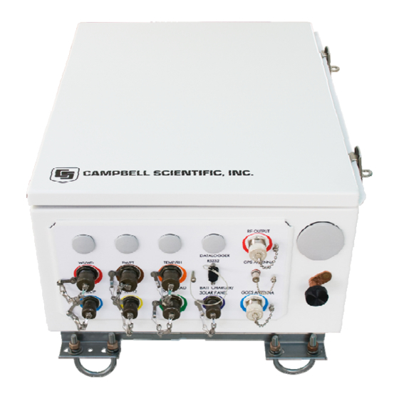
Page 11: Inside Environmental Enclosure (Optional Equipment Shown)
CR1000 Wiring Panel FIGURE 2-1. Inside environmental enclosure (optional equipment shown) The RAWS-P comes with a generic program. Modifications to NOTE this generic program will require datalogger support software (LoggerNet or PC400) purchased from Campbell Scientific. Please contact a Campbell Scientific Application Engineer for programming assistance. -
Page 12: Public Variables
RAWS-P Remote Automated Weather Station Use the CR1000KD Keyboard NOTE Display “Public Variables” shown in TABLE 2-1. • Connect the CR1000KD Keyboard Display to the CS I/O connector (FIGURE 5-5) or SC12 Cable (FIGURE 2-1) • Press any key for the CR1000KD Power up Screen •... -
Page 13: Station Siting And Orientation
RAWS-P Remote Automated Weather Station Clockgood True or False: True after GPS fix and CR1000 clock has been set to match TX320 clock TimeToXmit Seconds until transmit time. Indicates CR1000 and TX320 are properly setup and running Standing Wave Ratio (SWR), only after a transmission. Indicates condition of antenna and cable. -
Page 14: Precipitation
The HC2S3 Rotronic’s HydroClip2 Air Temperature and Relative Humidity Probe has a -RQ cable termination option that allows it to connect to the RAWS-P. This probe contains a Platinum Resistance Thermometer (PRT) and a Rotronic’s IN1 capacitive relative humidity sensor. Voltage is output for... -
Page 15: Wiring
Under the filter assembly, verify the sensors are connected but not touching. Try connecting a substitute sensor. Obtain an RMA number before returning this sensor to Campbell Scientific for repair. NOTE Consult the HC2S3-L manual for more information. -
Page 16: Troubleshooting
Try connecting a substitute sensor. Obtain an RMA number before returning this sensor to Campbell Scientific for repair. NOTE Consult the TE525-L manual for more information. -
Page 17: Wind Speed And Direction
Verify free movement of the cup anemometer and wind vane. Try connecting a substitute sensor. Obtain an RMA number before returning this sensor to Campbell Scientific for repair. NOTE Consult the 034B-L manual for more information. -
Page 18: 2-D Windsonic
Try connecting a substitute sensor. Should the 2- D sonic sensor be damaged, fails to output data, or sends a nonzero diagnostic, obtain an RMA number before returning this sensor to Campbell Scientific for repair. -
Page 19: Wiring
“5V” terminal. No voltage indicates a problem with the sensor or a bad sensor cable connection. Try connecting a substitute sensor. Obtain an RMA number before returning this sensor to Campbell Scientific for repair. NOTE Consult the CS100 manual for more information. -
Page 20: Wiring
Verify the CS506 sensor element is securely fastened. Try connecting a substitute sensor. Obtain an RMA number before returning the CS516-LQ sensor to Campbell Scientific for repair. NOTE Consult the CS506-L, CS205 and 107-L manuals for more information. -
Page 21: Wiring
The magnitude of the voltage output depends on the incident solar radiation. Check the sensor cable. Disconnect the connector and look for damaged pins. Try connecting a substitute panel. Obtain an RMA number before returning the SP10/20-LQ to Campbell Scientific for repair. NOTE Consult the SP10, SP10R, SP20, and SP20R Solar Panels manual for more information. -
Page 22: Wiring
NOTE An “external battery cable” (pn 6186) ships with the RAWS-P. Connect 12 V power to the datalogger and/or peripherals using the “+12 and Ground” terminals. The ON-OFF switch applies power to these 12 V terminals. -
Page 23: Troubleshooting
RAWS-P Remote Automated Weather Station 5.2.3 Troubleshooting If a problem is suspected, the CH100 may be checked by measuring: • input voltage between the two CHG terminals. From a solar panel, the voltage should be 15 to 28 Vdc. From the standard wall charger (pn 29796), the voltage should be 24 Vdc. -
Page 24: Troubleshooting
5.4.1 General Description The High Data Rate GOES Transmitter (pn TX320) shown in FIGURE 5-2 supports one-way communication, via satellite, from a Campbell Scientific datalogger to a ground receiving station. Satellite telemetry offers a convenient communication alternative for field stations where phone systems or RF systems are impractical or rendered unreliable after a tragedy to the local infrastructure. -
Page 25: Wiring
RAWS-P Remote Automated Weather Station FIGURE 5-2. GOES transmitter 5.4.2 Wiring The TX320 is mounted inside the RAWS environmental enclosure and the transmitter connections are described below. TABLE 5-1. GOES Transmitter Connections TX320 Connector Connects to CS I/O CR1000 CS I/O port via SC12 cable (shipped with the... -
Page 26: Troubleshooting
+11 to +14 Vdc. Check the SC12 cable connection between the CR1000 wiring panel and the TX320. Press the TX320 diagnostic button to query the state of the transmitter. If problems persist, try a substitute. Obtain an RMA number before returning this equipment to Campbell Scientific for repair. NOTE Consult the TX320 manual for more information. -
Page 27: Wiring
CR1000 wiring panel for 12 volt power. If the CR1000 is unresponsive to CR1000KD key strokes, there might be a problem with the CR1000 datalogger. If problems persist, try a substitute. Obtain an RMA number before returning this equipment to Campbell Scientific for repair. NOTE Consult the CR1000 manual for more information. -
Page 28: Wiring
12 volt power. If the CR1000 is unresponsive to CR1000KD key strokes, there might be a problem with the CR1000 datalogger. If problems persist, try a substitute. Contact a Campbell Scientific applications engineer for assistance. Obtain an RMA number before returning this equipment to Campbell Scientific for repair. NOTE Consult the CR1000 manual for more information. -
Page 29: References
RAWS-P Remote Automated Weather Station performance testing (for example, bearing torque), and sensor component replacement, generally requires sending the instrument to Campbell Scientific. A station log should be maintained for each weather station that includes equipment model and serial numbers and maintenance that was performed. -
Page 30: Magnetic Declination For The Contiguous United States
RAWS-P Remote Automated Weather Station in FIGURE 9-3. Note that when a negative number is subtracted from a positive number, the resulting arithmetic operation is addition. For example, the declination for Longmont, CO is 10.1°, thus True North is 360° ─ 10.1°, or 349.9° as read on a compass. Likewise, the declination for Mc Henry, IL is ─2.6°, and True North is 0°... -
Page 31: A Declination Angle East Of True North (Positive) Is Subtracted From 360 (0) Degrees To Find True North
RAWS-P Remote Automated Weather Station FIGURE 9-2. A declination angle east of True North (positive) is subtracted from 360 (0) degrees to find True North FIGURE 9-3. A declination angle west of True North (negative) is subtracted from 0 (360) degrees to find True North... -
Page 32: Usgs Web Calculator
RAWS-P Remote Automated Weather Station USGS Web Calculator The USGS provides an easy way of determining the declination of a specific site. Since magnetic declination fluctuates with time, it should be adjusted each time the wind sensor orientation is adjusted. The calculator can be accessed at: www.ngdc.noaa.gov/geomagmodels/Declination.jsp. - Page 34 Campbell Scientific Ltd. (CSL Germany) Fahrenheitstraße 13 28359 Bremen GERMANY www.campbellsci.de • info@campbellsci.de Campbell Scientific Spain, S. L. (CSL Spain) Avda. Pompeu Fabra 7-9, local 1 08024 Barcelona SPAIN www.campbellsci.es • info@campbellsci.es Please visit www.campbellsci.com to obtain contact information for your local US or international representative.
Need help?
Do you have a question about the RAWS-P and is the answer not in the manual?
Questions and answers