Table of Contents
Advertisement
Quick Links
Installation INSTRUCTIONS
ML25K
Micro Link™ Peep Hole Style
Standard IR Receiver
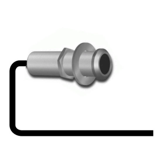
DESCRIPTION
The Micro Link IR Receiver is a small peep-hole style infrared repeater
assembly. The Micro Link IR Receiver is equipped with a 7-foot cable and a
3.5mm stereo mini plug, which is plugged directly into the "IR RCVR" jack on
the connecting block, such as the models 789-44, CB60, and 791-44. The
Micro Link IR Receiver is primarily intended for use in installations where the
connecting block is within reach of its 7-foot cable – as when installing the
Micro Link IR Receiver in a cabinet where the controlled equipment is behind
closed doors.
FEATURES
•
Small size; mounts in 1/2" diameter hole. 2 inches deep (50mm).
•
Quick-Connect 3.5mm Stereo Mini Plug on 7ft. cable for direct plug-in to
Xantech Connecting Blocks.
•
Works in normal 3-wire mode (12VDC, IR, GND).
•
Green Talkback LED for System Verification.
•
Includes 789-44 Connecting Block, Power supply, and four 283D emitters
for easy system installation.
SPECIFICATIONS
•
Infrared modulation frequency bandwidth: 25 – 60 kHz.
•
IR reception range: Up to 80 feet, depending on remote control output
strength and ambient conditions.
•
Reception angle: 55 degrees off axis for 50% range reduction.
•
Cable requirements: 3-conductor. Use 24 gauge up to 200', 22 gauge up
to 600' 20 gauge up to 2000', 18 gauge up to 5000' – unshielded OK.
•
Max. transmission length: 1 mile using 18 gauge wire.
•
Maximum current output: 100mA
•
Drives IR emitters through Xantech Connecting Blocks, Controllers, etc.
•
Dimensions: 1/2" diameter x 2" deep (13mm x 50mm).
•
Power requirements: +12VDC, 20mA.
1
Advertisement
Table of Contents

Related Manuals for Xantech ML25K


Summary of Contents for Xantech ML25K
- Page 1 • Max. transmission length: 1 mile using 18 gauge wire. • Maximum current output: 100mA • Drives IR emitters through Xantech Connecting Blocks, Controllers, etc. • Dimensions: 1/2” diameter x 2” deep (13mm x 50mm). • Power requirements: +12VDC, 20mA.
- Page 2 “OUT” jack. If expansion beyond two emitters is required, use the included The IR receiver should be located so that it is not directly facing a light source Xantech 789-44 Connecting Block. such as lamps or displays (standard, LCD, and Plasma). When mounted near...
- Page 3 ML Series Amplified Satellite Receiver IR Receivers target resulting in improved remote control interaction. Featuring color-coded Connecting Block connectors, a Xantech IR Kit is now an easy to install, and allows a worry-free installation. Emitter INCLUDED ITEMS Emitter AV Receiver...
- Page 4 STEP 3: Plug in the 283D Designer Emitters 3.5mm mono mini plug (ITEM C) into the ITEM C: (4) 283D Designer Emitters jacks labeled EMITTERS on the 789-44 (ITEM B) and affix the opposite end to the IR Sensor Window of the controlled equipment. Extra double sided adhesive tape is included.
- Page 5 IR Troubleshooting Guide Symptom #2: TB LED on IR Receiver (and/or Emitters) Dimly lit or flickering Cause: Solution NOTE: Due to the many variables in a given installation, the Signal and ground wires are troubleshooting countermeasures you will have to take may vary from job reversed or shorted either at the Recheck your wiring.
- Page 6 Symptom #3: TB LED on IR Receiver (and/or Emitters) on solid Symptom #4: TB LED on IR Rec. blinks but 283D or 286D 'Blink' style Emitters do not Cause: Solution Cause: Solution Use a 85 or 95 series Plasma 'Friendly' There may be a short, such as a Receiver.
- Page 7 Symptom 6: Emitters function but some (or all) components do not respond. Symptom #7: Absolutely No Functionality (How to determine which component is at fault) Cause: Solution Component to Test Instructions Reposition the Emitter so that it is directly With a Multimeter, measure the DC Voltage of the over the components sensor window.
- Page 8 Limited Warranty Xantech® warrants its products to be free of defects in materials or workmanship. This is a Limited Lifetime warranty from the date of purchase by the original consumer. Any products returned to Xantech and found to be defective by Xantech within the warranty period will be repaired or replaced, at Xantech’s option, at no charge.
Need help?
Do you have a question about the ML25K and is the answer not in the manual?
Questions and answers