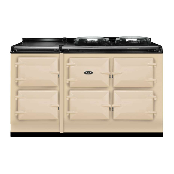
Table of Contents
Advertisement
Quick Links
NOTE: THESE INSTRUCTIONS SHOULD BE LEFT
WITH THE APPLIANCE AND THE USER TO RETAIN
FOR FUTURE REFERENCE.
Aga Gas Fired ranges are delivered unassembled.
Before installation can be made the site is inspected for
suitability by an Authorised Aga Distributor and corrected
where necessary to conform with local installation codes
or in the absence of local codes with:
In Canada:
The CAN/CGA-B149 installation codes.
In U.S.:
The National Fuel Gas Code ANSI Z223. 1-latest edition.
Assembly is undertaken on site by the same Aga
Distributor to ensure correct performance and safety.
BASE OR HEARTH
It is essential that the base or hearth on which the range
stands should be level and strong enough to support the
weight of the range.
Approximate weights:-
Models GC (Open Flue) and GC (Direct Vent)
- 408kg (900lb)
Models GE (Open Flue) and GC (Direct Vent)
- 585kg (1290lb)
Installation Instructions for Aga Gas Fired Range
Models:
GC Open Flue Range (2 Oven)
GC Direct Vent Range (2 Oven)
GE Open Flue Range (4 Oven)
GE Direct Vent Range (4 Oven)
For U.S. and Canadian Markets
1
The top face of the hearth must be of non-combustible
material for a minimum thickness of 12mm (1/2in) and
comply with current Building Regulations and National
Fire Laws.
OPEN FLUE RANGE -
MODELS GC AND GE
The wall behind the cooker draft hood and flue connector
must have a minimum air gap of 57mm (2 1/4"). Any
openings in the wall behind the range or in the floor under
the range must be sealed before appliance installation.
Ensure the draft hood is securely bolted to the support
spigot as shown in Fig. 2.
NOTE: THIS IS NORMALLY FITTED AND SECURED BY
THE FACTORY BEFORE DESPATCH.
DIRECT VENT RANGE-
MODELS GC AND GE
The wall behind the range must be the outside wall for
the venting of flue products. Wall thickness between
150mm (6 in) and 355mm (14 in) can be catered for at the
same time as site inspection.
Alternatively, special lengths can be offered to order up to
a maximum of 610mm (24 in) long.
Open Flue - Models GC and GE
04/08 EINS 33644
Advertisement
Table of Contents

Summary of Contents for AGA GC Open Flue Range
- Page 1 The National Fuel Gas Code ANSI Z223. 1-latest edition. THE FACTORY BEFORE DESPATCH. DIRECT VENT RANGE- Assembly is undertaken on site by the same Aga MODELS GC AND GE Distributor to ensure correct performance and safety. The wall behind the range must be the outside wall for the venting of flue products.
-
Page 2: Vent Connection
Termination at the roofs eaves is unacceptable. recommended in ANSI/NFPA 211 and according to The Aga Distributor or Local Gas Company should be manufacturers instructions. Chimneys and vents shall advised where any doubt arises as to the suitability of terminate above roof level and in accordance with the the flue. - Page 3 The following notes are intended to give general guidance. 355mm (14in) overall thickness. 1. The range must be installed so that the flue terminal is For special lengths up to 610mm (24in), consult your local Aga exposed to the external air and terminal clearances comply Distributor.
-
Page 4: Location Of Name Plate
The model and serial numbers for this appliance are found on the name plate. These numbers must be used when requesting advice from your Aga Distributor. The name plate is located on the inside face of the outer burner door. The maximum gas inlet pressure at the appliance must not exceed 12 inches w.g. - Page 5 INITIAL LIGHTING OF RANGE position, whereupon the main burner will light. Leave in the low fire position for at least 30 minutes. In a cold range, difficulty may be experienced in maintaining NOTE: Any attempt to rotate the control knob before the main burner alight on initial light-up only.
-
Page 6: Technical Specification
REPLACEMENT PARTS Range Model GC/GE GC/GE In the event of a component failure which requires replacement, contact your local Aga Distributor who will Main Burner advise and supply the necessary replacement. Injector Expendable components that will require replacing at some... - Page 7 Fig. 12 Pilot/Thermocouple DESN 512827...
-
Page 8: Yearly Service
Clean any carbon away from the electrode. With Aga's policy of continuous product improvement, the Company reserves the right to change specifications and make modifications to the appliance described and illustrated at any time.


