Table of Contents
Advertisement
Quick Links
See also:
Manual
Advertisement
Table of Contents

Related Manuals for AOR The New Classic AR3030


Summary of Contents for AOR The New Classic AR3030
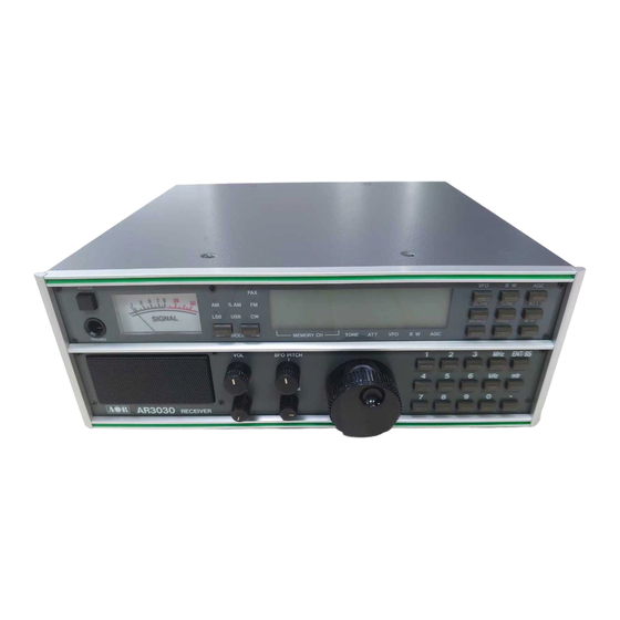
- Page 1 T T T T T N N N N N C C C C C LASSIC LASSIC LASSIC LASSIC LASSIC AR3030 General Coverage Receiver 30kHz ~ 30MHz ALL MODE *Collins mechanical filter inside...
-
Page 2: Introduction
AOR Ltd. AOR and the [AOR] logo are trade marks of AOR, Ltd. * Collins is a trade name of Rockwell International. The use of Collins and “Collins inside”... -
Page 3: Table Of Contents
AR3030 operating manual (2) Table of contents Introduction... Accessories supplied... Table of contents... Major features... Precautions... Location... Looking after your receiver... Power requirements.. Aerial (antenna) connection... Controls and functions... Front panel On/Off power switch... Headphone socket... Mode keys and indicators... - Page 4 AR3030 operating manual 5-36 VHF ANT - VHF socket... 5-37 LIGHT switch... 5-38 BATT compartment... Basic manual operation on the receiver... Tuning the receiver using the rotary control... Changing receive mode... Changing VFO A/B... Tone - Audio tailoring... Bandwidth and filters...
-
Page 5: Major Features
(3) Major features General The AR3030 offers the very latest technology through use of its’ DDS (Direct Digital Synthesizer). The legendary Collins 6kHz AM filter is fitted as standard to provide the highest levels of AM selectivity. High stability is accomplished by the standard fitting of a TCXO (Temperature Compensated Crystal Oscillator). - Page 6 The inclusion of SSB on the AR3030 adds a new dimension to the listening potential of the receiver when compared to AM broadcast-only shortwave receivers.
- Page 7 Attenuator, whip amplifier and aerial input & AGC The AR3030 does not contain RF amplification prior to the band-pass filters, all gain is applied in the more selective IF stages. This ensures the highest immunity to intermodulation effects often caused by the high number of strong signals encountered on the shortwave bands.
- Page 8 Loudspeaker and audio output The AR3030 has a built-in 66mm 3 WATT loudspeaker. A 3.5mm jack socket is located on the rear panel of the receiver for external speaker connection. Connection to this socket automatically cancels audio from the internal speaker.
-
Page 9: Precautions
4-3 Power requirements The AR3030 is designed for operation from an external DC supply of 11 - 16V DC at approximately 0.7A minimum or from internal fitted dry batteries. Always use the mains power supply provided, or from a regulated DC power supply of 13.8V @ 0.7A or more using the optional DC3000 connecting lead. -
Page 10: Aerial (Antenna) Connection
Blue: Neutral The AR3030 power supply has no connection to the EARTH pin of the mains plug. However a separate earth point is provided on the rear panel of the AR3030 for connection to a water pipe, central heating system radiator or external earth rod. -
Page 11: Controls And Functions
* For further information please refer to section 10 of this manual regarding aerial and earth systems. (5) Controls and functions The AR3030 receiver is housed in a strong metal cabinet. Controls for operation are located on the top and front of the cabinet with connections to the rear. - Page 12 AR3030 operating manual...
-
Page 13: Headphone Socket
The AR3030 has two VFOs’ (two selectable tuners) so that the user may quickly swap between and tune around two frequency bands with a single press of the... -
Page 14: Scan Key
SCAN DELAY. 5-8 BW - BandWidth key The BW key allows selection of filter bandwidth as indicated by the “[NOR]” (normal) and “[NRW]” (narrow) indicators on the LCD. The AR3030 is fitted with several standard IF bandwidths. AM/S.AM 6kHz/-3dB in the normal position using the legendary Collins eight resonator mechanical filter and a 2.4kHz/-6dB Murata ceramic filter in the narrow position. -
Page 15: Tone Key
AR3030 operating manual 2.4kHz Murata ceramic filter in the Normal position. An optional 500Hz/-3dB Collins seven resonator mechanical filter may be optionally fitted in the Narrow position. 15kHz Murata ceramic filter fixed. Selection of Normal/Narrow is disabled. 5-9 TONE key Audio quality may be tailored to suite the type of listening. -
Page 16: Att - Attenuator Key
0dB (no indication on the LCD - normal setting), -10dB “[10dB]” indicated and -20dB “[20dB]” indicated. The AR3030 does not contain RF amplification prior to the band-pass filters, all gain is applied in the more selective IF stages. This ensures the highest immunity to intermodulation effects sometimes caused by a large number of strong signals encountered on the shortwave bands. -
Page 17: Mhz] Mhz Key
AR3030 operating manual 5-16 [MHz] MHz key The [MHz] key is used to complete frequency entry when MHz selection is required i.e. while in VFO mode [4] [.] [7] [2] [2] [MHz] While in VFO mode, this key alters selection of tuning rate to MHz. An underscore “[ _ ]”... -
Page 18: Volume Control
AR3030 operating manual keypad / VFO lock. Press the key a second time to deactivate keypad lock. The receiver will always deactivate keypad/VFO lock when switched Off/On. 5-20 Volume control The volume control is located on the front panel underneath the mode switches. -
Page 19: Rf Gain Control
As with other receivers, the calibration may not be reliable on FM mode. 5-26 Loudspeaker (internal) The AR3030 is fitted with a large 66mm 3 WATT internal loudspeaker. Due to clever design, sound is projected through a small front mounted speaker grille. - Page 20 AR3030 operating manual...
-
Page 21: Ex Power - External Power Connection
AR3030 operating manual 5-27 EX POWER - external power connection This is a special switching three pin socket designed to accept external DC input of a nominal 13.8V DC @ 0.7A negative ground. You may either connect the power supply provided or another suitable supply such as a 12V car battery... -
Page 22: Fax - Fax Audio Output Socket
AR3030 operating manual speaker but not a headphone if connected to the front panel socket. An external speaker should have a nominal 8 OHM impedance and power handling of 2 WATTS or greater. 5-30 FAX - FAX audio output socket This 3.5mm mono jack socket is designed to provide a suitable audio character-... -
Page 23: Ant Selection - Selection Switch
In the right position the 50 OHM BNC aerial socket is selected allowing connection to low impedance coaxial aerials such as dipoles, magnetic baluns, loop aerials (AOR LA320), coaxial fed systems (like the AOR WA7000 active aerial) or an aerial tuning unit. -
Page 24: Basic Manual Operation On The Receiver
There is further aerial information in this manual (section 10). If in doubt please consult your dealer. Connect the AR3030 to an appropriate DC power source using either the supplied AC adaptor or optional DC3000 DC lead. Never connect the receiver directly to the mains. -
Page 25: Tuning The Receiver Using The Rotary Control
AR3030 operating manual 6-1 Tuning the receiver using the rotary control The receiver may be immediately tuned via the rotary tuning control. The free running tuning knob is used to select receiving frequency and in memory mode for selection of memory channel. - Page 26 SSB and a smaller frequency bandwidth is required than most other modes. The AR3030 uses true carrier re-insertion so that voice becomes intelligible. However due to the complexities of SSB, audio never sounds 100% natural and often listeners comment on it sounding a little like “Donald Duck”...
-
Page 27: Changing Vfo A/B
In the true sense of the word, “VFO” stands for Variable Frequency Oscilla- tor. Of course as technology improved so modern receivers do not strictly use a VFO, in the case of the AR3030 a Direct Digital Synthesizer (DDS) is employed. -
Page 28: Tone - Audio Tailoring
TONE Low position cut off frequency 1800 Hz TONE key inoperative. Frequency set to 800 Hz TONE key inoperative 6-5 Bandwidth and filters The AR3030 is fitted with several standard IF bandwidths including a cascade 8kHz/- 6dB ceramic filter (CFU455G2) for AM/ SSB/FAX/CW plus two audio bandwidths: AM/S.AM... -
Page 29: Agc - Automatic Gain Control
6-7 ATT - Attenuator operation The attenuator can be useful for reducing the level of unwanted strong signals or overload. The AR3030 has three settings for ATT, these being 0dB (no indication on the LCD - normal setting), -10dB [10dB] indicated and -20dB [20dB] indicated. -
Page 30: Rf Gain Control
6-9 SQUELCH control In the absence of a signal, background white noise may appear quite loud especially in FM mode. For ease of listening the AR3030 is fitted with an “all mode” squelch circuit. The squelch control should be rotated clockwise until the background noise just disappears and be carried out when no signal is present. -
Page 31: Vfo And Keypad Lock
AR3030 operating manual To activate the BFO in VFO mode press the [0] key followed by [mtr]. The LCD will display a “o” to indicate that manual BFO mode has been selected. If the BFO PITCH control is rotated it will initially sound like a fine tuning control. -
Page 32: Entering A Frequency Via The Keypad
For example, to select 14.10000 MHz follow the key sequence: [1] [4] [.] [1] [MHz] (MHz frequency entry) You will note that the trailing zeros are not required as the AR3030 completes the entry at the time the [MHz] key is pressed. -
Page 33: Memory Mode
AR3030 operating manual Correcting frequency input errors via the keypad Should you make a mistake when entering a frequency via the keypad there are two methods of correction. Back Space delete The [ENT/BS] key acts as a “BS” Back Space just like a computer keyboard deleting data input from the right hand side. -
Page 34: Memory Write
Automatic: Press the [M.in] key and the AR3030 will automatically select the first lowest number empty memory channel (unless they are all in use in which case channel [00] is always selected). The memory channel number will appear on the lower left hand side of the LCD and will flash to indicate memory write mode. -
Page 35: Deleting Memory Contents
AR3030 operating manual Manual: It is possible to store VFO data into any of the 100 memory channels and over- write current data if required. Let’s assume that you have 14.25000 MHz USB displayed in VFO mode and you wish to write into memory channel number 25 which has not been previously used. - Page 36 AR3030 operating manual Enter the two digit memory channel number which you wish to erase such as [2] [3]. The legend “—” will be replaced by memory channel number which you have selected “23” and will flash. Complete the delete sequence by pressing the [ENT/BS] key. A beep confirms correct data entry and the completion of the delete sequence.
-
Page 37: Memory Channel Scan
The display will return to VFO mode automatically after approximately six seconds. 6-16 Memory Channel Scan It is sometimes useful to instruct the AR3030 to automatically monitor a number of memory channels especially when activity is low. This process is known as “scanning”. -
Page 38: Program Memory Channel Scan
To resume scanning once again simply press [SCAN]. 6-17 Program Memory Channel Scan It is possible to instruct the AR3030 to scan a group of memory channels rather than all channels which contain data. This is a convenient method of scanning a few memory channels without needing to delete temporarily unwanted memory channels. -
Page 39: Pass Channel Operation
6-19 Pause time programming in scan mode The AR3030 does not immediately scan from channel to channel rapidly. This is to allow the receiver’s AGC and other circuitry to react to the changing noise... -
Page 40: Delay Time Programming In Scan Mode (Vhf Only)
While in VFO mode press [SCAN] to start memory channel scan. Press [MEMO] to inform the AR3030 that you wish to reprogramme scan pause time. The LCD will show “PAUSE 5” and the figure 5 flashes to indicate the present value. -
Page 41: Computer Control (Rs232C)
Press [ENT/BS] to complete the sequence which is confirmed by a beep. The scan delay time will now be 0.8 seconds. Computer control (RS232C) The AR3030 is capable of remote control via the 9 pin female D-type rear connector (section 5-31) using a simple RS232 cable without the need for an interface. -
Page 42: Communication Parameters
AR3030 operating manual 7-2 Communication parameters If using a terminal driver configure the following communications parameters: Type of communication - Semi duplex (no receive while transmitting) Baud rate speed - 4800 or 9600 BPS (refer to start-up) Stop bit - 2 Bits... -
Page 43: Monitoring The Contents Of Received Serial Data
AR3030 operating manual 7-5 Monitoring the contents of received serial data Data to be transmitted FORMAT D [CR] All received data. Go to VFO mode from Memory mode. Y [CR] Send signal level (64 div 00 - 3F) nn M [CR] Go to Memory mode after sending data of selected memory channel. -
Page 44: Format 2 - Reading The Receiver's Signal Strength
AR3030 operating manual S or S.AM N or 7-7 FORMAT 2 - Reading the receiver’s signal strength Contents of transmission === nn [CR] [LF] Contents of TX Details - Send the S-Meter Readings in 64 steps 00 ~ 3F 7-8 FORMAT 3 - Transmitting the memory contents... - Page 45 AR3030 operating manual 0 B [CR] - Selection of FILTER NORMAL 1 B [CR] NARROW 0 T [CR] - Selection of TONE 1 T [CR] HIGH nnn.nnnn [CR] - Enter the frequency (MHz) and go to the dial (VFO) mode.
-
Page 46: Optional Accessories
(8) Optional accessories VHF converters Two separate optional VHF internal converters are planned for the AR3030 but only one may be fitted at a time. It’s fitting is recommended in a workshop. The frequency limits of the VHF converters are: 108.00000 MHz to 139.99999 MHz... -
Page 47: Trouble Shooting - Microprocessor Reset
This lead comprises an 8 pin DIN plug on one end for connection to the AR3030 with a 3.5mm audio plug on the other for connection to a tape recorder with a 2.5mm plug for control On/Off of the tape motor. -
Page 48: Aerials (Antennas) And Earth Systems
Telescopic whip aerials Whip aerials may be connected to the 50 OHM BNC aerial input of the AR3030 and the whip aerial switch position selected. The selection of “WHIP” adds a small preamplification to the receiver’s input stages and matches the very high... - Page 49 For shortwave reception a random length of long wire approximately 10 to 20 metres in length forms a good compromise. The wire should be fed into the high impedance aerial input of the AR3030 receiver. If possible try to locate the receiver close to a window so that the wire has the shortest and most direct run from the rear of the receiver to the outside World.
- Page 50 For the very best results you should consider a dedicated aerial such as a single or multi-band dipole or similar aerial. The problem with a wide coverage receiver like the AR3030 is that for the ultimate results many dedicated aerials are required to cover the whole spectrum. This may involve complex aerial switching and reduces the ability to quickly monitor many bands.
- Page 51 Loop Aerials Desk-top loop aerials have the advantage of small size (such as the AOR LA320). They too have tuning controls to reject unwanted signals. As the loop is within easy reach of the operator it can be rotated to provide directivity.
-
Page 52: Propagation - Shortwave Bands
The AR3030 power supply has no EARTH connection to the mains plug. However a separate earth point is provided on the rear panel of the AR3030 for connection to a water pipe, central heating radiator or external earth rod. If fitting a separate external earth rod, consider the implications carefully if your mains supply uses Protective Multiple Earth (PME) system. - Page 53 AR3030 operating manual When the reflected signals reach the Earth again they may either be received or reflected back up into space. If lucky, they will be reflected by the ionosphere yet again down toward the Earth providing reception into another and possibly more distant location.
- Page 54 AR3030 operating manual Occasionally a similar effect can be caused by temperature inversion layers creating “tropospheric propagation” selectively “ducting” transmissions between two points. Tropospheric propagation is usually applicable to the higher VHF and UHF bands. “F1” & “F2” layers During the day time there are two upper layers of the ionosphere, these being the “F1”...
-
Page 55: Specification
AR3030 operating manual (12) Specification Model... AR3030 Receiver coverage... 30 kHz ~ 30MHz Tuning selection... MHz, kHz, 100Hz, 10Hz (5Hz minimum step) Receiving modes... AM, S.AM, USB, LSB, CW, FAX & NFM Frequency stability... 5 ppm -10 to +50 degrees C Number of memory channels... - Page 56 AOR, LTD. 2-4-6 Misuji, Taito-ku, Tokyo 111 Japan. Tel: 03 3865 1681 © AOR, LTD. 1993...
Need help?
Do you have a question about the The New Classic AR3030 and is the answer not in the manual?
Questions and answers