Table of Contents
Advertisement
Advertisement
Table of Contents

Related Manuals for Garmin GPS 100


Summary of Contents for Garmin GPS 100
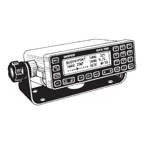
- Page 1 GPS 100 PERSONAL NAVIGATOR OWNER'S MANUAL GARMIN...
- Page 2 GPS 100 Personal Navigator OWNER'S MANUAL...
- Page 3 GARMIN. Information in this document is subject to change without notice. GARMIN reserves the right to change or improve their products and to make changes in the content without obligation to notify any person or organization of such changes or improvements.
- Page 4 This manual and accompanying quick reference card provide complete information on safely operating the GPS 100 to its full potential. An exciting practice voyage has been planned for you to practice your navigation skills using the built-in simulator. Afterwards try a trip of your own to realize the...
- Page 5 NAVAIDs, visual sightings, charts, etc. For safety, always resolve any discrepancies before continuing navigation. The altitude calculated by the GPS 100 is geometric height above mean sea level and could vary significantly from altitude displayed by pressure altimeters in aircraft.
-
Page 6: Table Of Contents
TABLE OF CONTENTS CHAPTER INTRODUCING THE GARMIN GPS 100 GETTING STARTED - GPS 100 FUNDAMENTALS 2-1 INITIALIZATION WAYPOINTS NAVIGATION INFORMATION GETTING THERE FAST — GOTO GPS 100 Capabilities Basic Package Optional Accessories Operational Modes Keypad Operation Entering Data Viewing Messages... - Page 7 DATE AND TIME FUNCTIONS 10.1 Date and Time 10.2 Alarm Clocks 10.3 Event Timers 10.4 Sunrise/Sunset 10.5 Battery Timer CUSTOMIZING THE GPS 100 11.1 GPS Status 11.2 User Selectable Alarms 11.3 CDI Settings 11.4 Offset Navigation/Magnetic Variation 11.5 Audio/Display Characteristics 11.6...
- Page 8 Battery Pack Operation 14.6 Maintenance 14.7 Customer Support SAMPLE SIMULATED TRIP APPENDICES GPS — HOW DOES IT WORK GPS Overview Coverage and Accuracy GPS Receiver Designs ACRONYMS AND ABBREVIATIONS LOCAL TIME TO UTC TIME CONVERSION INDEX 12-4 12-5 13-1 14-1 14-1 14-3...
-
Page 9: Introducing The Garmin Gps 100
INTRODUCING THE GARMIN GPS 100 1.1 GPS 100 CAPABILITIES The GPS 100 provides a host of powerful capabilities which were previously unavailable or found only in much larger and more expensive systems: · Performance: eight satellites while providing high receiver sensitivity, fast first fix, and continuous navigation updates. -
Page 10: Basic Package
· Warranty Card The basic package allows you to use your GPS 100 for both portable and fixed operations. The unit may be operated from external AC power using the battery charger, external 12 or 24 volt DC power using the power/data cable, or using a battery pack. -
Page 11: Optional Accessories
(signal reception through thin fabric such as canvas may be adequate but degraded). A wrist strap is provided to prevent accidental dropping of your GPS 100. (Connect the wrist strap to the eyelet on the back of the unit.) Gimbal Mount Operation: A gimbal mount is supplied for fixed installation in a boat or land vehicle. -
Page 12: Operational Modes
A carrying case is available for convenient storage or transportation of your GPS 100. This case can be worn on your belt or over the shoulder. A utility pocket is provided for storing spare battery packs as well as other small items. - Page 13 GPS 100 and is ideal for planning routes and entering waypoints. Keep in mind that the GPS 100 is not tracking satellites in the simulator mode. You should never attempt to use the simulator mode for actual navigation.
-
Page 14: Getting Started - Gps 100 Fundamentals
Notice the “M” character in the upper right-hand corner of the display illustrated above. This symbol is known as the Message Annunciator and will flash if the GPS 100 wishes to tell you something. The unit also contains an internal tone generator that will sound with the flashing Message Annunciator (if your unit is connected to an external alarm system, it will also be activated). -
Page 15: Keypad Operation
The area of the page with light characters and dark background is called the cursor. The cursor may be moved to locations on the page called fields. A field is a group of characters treated as a single unit of information which allow you to enter data. - Page 16 The alphanumeric keys allow you to enter letters and numbers into the GPS 100. If you want to enter a number, for instance “1”, simply press the 1 key. If you want to enter a letter, for example “A”, press the 1 key, then press the right arrow key once to select “A”...
-
Page 17: Entering Data
2.2 ENTERING DATA The GPS 100 features a keypad feedback tone which will sound each time you press a key. If you enter data which is not appropriate for the field, the feedback tone will quickly sound three times indicating an error. The keypad feedback tone can be turned off if you wish (see Section 11.5 for more... -
Page 18: Viewing Messages
Press the CLR key. 2.3 VIEWING MESSAGES From time to time, the GPS 100 will use a message to tell you of conditions that need your attention. When the GPS 100 has a new message for you, the Message Annunciator will flash. When this occurs, press the MSG key to view new message(s). - Page 19 Refer to Chapter 13 for a complete list of GPS 100 messages.
-
Page 20: Initialization
14 hours before actual field use.) SELF TEST PAGE When you turn your GPS 100 on, the Self Test Page will be displayed for approximately 2 seconds. During this time, the GPS 100 will conduct a series of self tests. - Page 21 To update the initial date... · Use the right or left arrow key to position the cursor over the date field. · Press the number keys associated with the UTC day of the month. For example, to enter the 14th day of June, press the 1 key followed by the 4 key.
- Page 22 · Press the ENT key when your longitude is correct. Alternatively, you may enter the name of a nearby waypoint. The GPS 100 will use the position of the waypoint as its initial position. You will find this method convenient if the nearby waypoint is already programmed and stored in memory (see Chapter 4 for information on waypoints).
-
Page 23: Mode Selection Page
Your GPS 100 is now initialized and the Satellite Status Page will be displayed (see Section 11.1 for more information on the Satellite Status Page). If you are not operating your GPS 100 in the Simulator mode, it will immediately begin acquiring satellites. This processs is fully automatic and, under normal circumstances, will take 2-3 minutes to obtain navigation information. - Page 24 Where to go from here... If you are using your GPS 100 for the first time, we encourage you to review Chapter 4 on waypoints, Chapter 5 on navigation, and Chapter 6 on GOTO.
-
Page 25: Waypoints
CHAPTER 4 WAYPOINTS One of the many powerful features of the GPS 100 is its ability to create, store, and use 250 alphanumeric waypoints. A waypoint consists of a name (up to five letters or numbers) and its latitude/longitude location. You will have the opportunity to use waypoints extensively while operating the GPS 100. -
Page 26: Waypoint Definition
When a waypoint name has been entered that does not exist in memory, the GPS 100 will assume you wish to create a new waypoint. The New Waypoint Page will ask you to select one of three methods for defining the waypoint position: direct latitude/longitude entry, relative to an existing waypoint, or relative to your present position. - Page 27 To enter the waypoint position directly... · Place the cursor over “ENTER POSN?” and press the ENT key. The Waypoint Definition Page will appear with the cursor over waypoint latitude as illustrated below. · Enter the waypoint latitude. · Enter the waypoint longitude. ·...
-
Page 28: Using Waypoints
To create a waypoint offset from your position... · Move the cursor over “RELATIVE TO PRES POSN?” and press the ENT key. The Waypoint Definition Page will appear with the cursor over the bearing and your position will be displayed on line 2 as illustrated below. -
Page 29: Using Waypoints By Scanning
4.4 USING WAYPOINTS BY SCANNING The GPS 100 offers a waypoint scanning feature which will simplify waypoint name entry. A waypoint list is available for scanning in any waypoint name field. The list consists of up to nine nearest waypoints within 100 nm and a complete list of waypoints which are organized alphabetically (numbers are ordered before the letters of the alphabet). -
Page 30: Reviewing Waypoints
4.5 REVIEWING WAYPOINTS The GPS 100 allows you to quickly review waypoint information without entering the waypoint name. For example, you may review the waypoints in a route, or review the definition of the nearest waypoints. In general, if the cursor is over a waypoint name, you may quickly review the definition of that waypoint. -
Page 31: Nearest Waypoints
Rank Name An important feature of the GPS 100 is the ability to display up to 9 waypoints nearest to your position (not further than 100nm). In an emergency, you may use the nearest waypoint feature to find the closest point of safety in your area. - Page 32 Pilots may wish to define a proximity alarm waypoint around a restricted use airspace such as a MOA or TCA. The GPS 100 will notify you with an alarm tone and the message “PROX ALARM-PRESS NAV” if you enter the alarm circle.
-
Page 33: Waypoint Catalog
GPS 100 on as long as the overlap remains. (WARNING: If you enter the overlap area, the unit will only inform you of the nearest proximity waypoint.) To remove a waypoint from the proximity list... - Page 34 right arrow key to scroll down the list. · Place the cursor over the first waypoint name on line 1 and press the left arrow key to scroll up the list. The Waypoint Catalog Page allows you to delete waypoints which are not used in any route and are not members of the proximity list.
-
Page 35: Navigation Information
CHAPTER 5 NAVIGATION INFORMATION The GPS 100 features four navigation pages. You may cycle through these pages as illustrated below by pressing the NAV key until the desired page is displayed. In addition, you may access a wide array of planning functions using the navigation menus. -
Page 36: Cdi And Navigation Summary
GOTO function, the CDI Page will appear as illustrated below (see Chapter 6 for more details on the GOTO function). If the GPS 100 is not navigating to a waypoint (i.e., there is no “active to” waypoint), the CDI area will indicate this condition as illustrated below. - Page 37 The cyclic fields, indicated by the “>” character, can be used to select the type of information you wish to see. To use a cyclic field, place the cursor to the right of the “>” and press the CLR key. You may select one of two velocity options: ·...
- Page 38 · RNG - Range. RNG is the distance from your position to the “active to” waypoint. · ATD - Along track distance. ATD is the along track distance to the “active to” waypoint. It is measured from the point on the course closest to your position.
-
Page 39: Present Position
· ETE-Estimated time enroute. ETE is the time it will take to reach the “active to” waypoint based on your speed. · ETA- Estimated time of arrival. ETA is the time at which you will arrive at the “active to” waypoint based on your speed. ·... - Page 40 If the GPS 100 needs altitude to perform 2D navigation, you will be informed with the message “NEED ALT - PRESS NAV”. When you press the NAV key, the Position Page will be displayed as illustrated below: The last known altitude will be displayed to the right of “ALT:”...
-
Page 41: Getting There Fast - Goto
Place the cursor over the GOTO waypoint name on the CDI Page. · Press the CLR key, the GOTO waypoint name will become blank. · Press the ENT key. The GPS 100 will navigate using route 0, if available. CHAPTER 6 GOTO Waypoint... -
Page 42: Routes
CHAPTER 7 ROUTES The GPS 100 allows you to create and store 10 routes, numbered 0 through 9, containing up to 9 waypoints each. Routes can be travelled in the order in which you define the waypoints, or they may be reversed. -
Page 43: Navigating Using Routes
The GPS 100 also features automatic leg sequencing. As you pass a waypoint in the route, the unit will automatically select the next waypoint as the “active to” waypoint. If your speed is greater than 65 knots, the GPS 100 will provide smooth steering around the turn. -
Page 44: Route Catalog
7.2 ROUTE CATALOG Route Number The Route Catalog Page gives a list of the routes stored in the GPS 100. This page shows the route number, first/last waypoint names composing the route, and the total distance traversed by the route. For example, in the illustration above, route 0 begins at FTMYR (Fort Myers, Florida), ends at NASAU (Nassau in the Bahamas), and is 364.8 nautical miles long. -
Page 45: Editing Routes
7.3 EDITING ROUTES The Route Review Page displays the waypoints of a route and allows you to create, change, review, and activate routes. To display the Route Review Page... · Place the cursor over the desired route on the Route Catalog Page and press the ENT key. -
Page 46: Activating Routes
· Move the cursor over the position in the route where you wish to enter the new waypoint. · Enter the new waypoint. The waypoints of the route will shift to the right to make room for the new waypoint. To delete a waypoint from a route... - Page 47 Immediately after activating a route, the Active Route Page will be displayed. This page displays the waypoints of the active leg on line 1, and up to 2 waypoints on lines 2 and 3. Distance and time information is displayed to the right of each waypoint name.
-
Page 48: Deleting Routes
7.5 DELETING ROUTES Routes can be deleted using the Route Review Page. To delete a route... · Place the cursor over the desired route on the Route Catalog Page and press the CLR key. The Route Review Page will be displayed as illustrated below. - Page 49 CPA waypoint name will be identical to the first 4 characters you entered plus a number (0..9). For example, if you entered “HOOZE”, the CPA waypoint will be named “HOOZ0”. If the GPS 100 cannot assign a unique name to the CPA waypoint, you will be informed with the message “INVALID CPA WPT”.
-
Page 50: Autostore Tm
Latitude The AutoStore function allows you to capture your position at the touch of a button so that you may easily return later. Additionally, you may record your navigation path by inserting the captured waypoints into a route. The AutoStore Page displays the AutoStore position, and optional storage route. - Page 51 · If you do not wish to store the waypoint in a route, make sure the route number is blank. · With the cursor over “OK?” press the ENT key. See Section 12.1 for an application example using the AutoStore function.
-
Page 52: Trip Planning
The GPS 100 allows you to perform trip and fuel planning, and calculate aviation data such as vertical speed, true airspeed, and wind. These functions are accessed from Navigation Menu 1, illustrated below, which is displayed by pressing the NAV key. To select a function from this menu, place the cursor over the desired function and press the ENT key. -
Page 53: Fuel Planning
The GPS 100 will display the distance and bearing between the two geographical points. In addition, the time requirement will be displayed based on speed. Use the cyclic field to select estimated time enroute (ETE) or estimated time of arrival (ETA). -
Page 54: Density Altitude/Tas (Aviation Feature)
· Enter the fuel flow in units per hour (e.g., gallons per hour.) The GPS 100 will calculate fuel requirements in the corresponding units (e.g., gallons) required to go from point 1 to point 2. In addition, the time requirement will be displayed based on speed. Use the cyclic field to select estimated time enroute (ETE) or estimated time of arrival (ETA). -
Page 55: Wind Aloft (Aviation Feature)
(the temperature read on a standard outside air temperature gauge found on most piston aircraft is TAT). The GPS 100 will display the resulting density altitude and true airspeed. The TAS computed on this page will automatically become the default value used in the wind aloft calculations described in the following section. - Page 56 · Use the CLR key to select the VNAV waypoint from the active route. The GPS 100 will display the required vertical speed. To activate the VNAV function... · Review the calculated vertical speed. If you wish to change the vertical speed, enter the desired vertical speed.
- Page 57 recommendations. Altitude and climb rate should be controlled by the pilot in command with due regard for airspeed and other aircraft performance limitations. You will be informed with the message “START ALTITUDE CHNG” when you are less than 15 seconds from the point at which the desired VNAV maneuver is to begin.
-
Page 58: Date And Time Functions
CHAPTER 10 DATE AND TIME FUNCTIONS The GPS 100 allows you to view current date and time, set alarm clocks and timers, and calculate sunrise/sunset times. These functions are accessed from Navigation Menu 2, illustrated below, which is displayed by pressing the NAV key. -
Page 59: Alarm Clock Page
The GPS 100 will keep track of local as well as UTC time. UTC, which is essentially the same as Greenwich Mean Time (GMT), does not change with local time zones. It is the time at 0 degrees longitude which passes through the city of Greenwich, England. -
Page 60: Event Timers
Press the CLR key to select “OFF” for the alarm clock. 10.3 EVENT TIMERS The GPS 100 features two timers available on separate pages. Each can be used as either an elapsed timer or count down timer. These timers can be useful for measuring the elapsed time since a certain event, or they can tell you when a specified amount of time has expired. -
Page 61: Sunrise/Sunset
· Move the cursor over “STOP?” and press the ENT key. The count down timer may be reset at any time while running or stopped. When reset, the count down timer value will return to its initial value. To reset the count down timer... ·... -
Page 62: Battery Timer
· Enter the desired waypoint name. If you wish to use your present position, leave it blank. · Enter the desired date. The GPS 100 will display the sunrise and sunset times for the waypoint and date you have entered. If you have selected local time on the Date/Time Page, the sunrise and sunset times will be displayed in local time. -
Page 63: Gps Status And Unit Customization
GPS STATUS AND UNIT CUSTOMIZATION The GPS 100 is designed for maximum flexibility. The unit features Setup Pages that allow you to customize your unit by setting a wide array of parameters. You may cycle through the GPS Status and Setup Pages as illustrated below by pressing the SET key until the desired page is displayed. -
Page 64: Gps Status
EPE and DOP.) The following is a list of possible receiver status messages : “ SEARCH SKY” The GPS 100 is in the process of searching the sky for visible satellites. You will be informed with the message “SEARCHING THE SKY”. “ACQUIRING”... -
Page 65: User Selectable Alarms
“NEED ALT” The GPS 100 needs altitude in order to start and/or continue 2D navigation. Go to the Position Page and enter altitude (see Section 5.2 for more information). “NOT USABLE” The GPS 100 is unusable (possibly due to incorrect initialization data or abnormal satellite conditions). - Page 66 Move the cursor over “OK?” and press the ENT key. The arrival alarm is now cleared. The GPS 100 is capable of monitoring your anchor for slippage. If your boat drifts away from the anchor position more than the specified distance, you will be informed with an alarm tone and the message “ANCHOR DRAG ALARM”.
-
Page 67: Cdi Settings
· Enter the anchor alarm distance. · Press the CLR key to select “ON” for the anchor drag alarm. · Move the cursor over “OK?” and press the ENT key. The anchor drag alarm is now armed. To turn off the anchor drag alarm... ·... -
Page 68: Offset Navigation/Magnetic Variation
Heading Mode Select OFFSET NAV/MAG VAR PAGE The GPS 100 features parallel offset navigation which allows you to track to the left or right of your course by a desired distance (see Section 12.2 for an application example using offset navigation). - Page 69 · Move the cursor over “OK?” and press the ENT key. The GPS 100 offers you three magnetic variation options. You may select TRUE, AUTO, or USER magnetic correction for all track, course, and heading information. If you select TRUE, all information displayed on other pages will be referenced to the true North pole.
-
Page 70: Audio/Display Characteristics
“NONE” to turn off both. · Move the cursor over “OK? and press the ENT key. While operating under battery power, the GPS 100 will automatically turn the backlighting off for you after a specified period of time (backlighting is 11-8... -
Page 71: Navigation Display Units
120 seconds, or “NONE” (which means the backlighting will never turn off while the unit is operating). · Move the cursor over “OK?” and press the ENT key. The GPS 100 display contrast may be adjusted to suit your viewing angle needs. To change the display contrast... ·... -
Page 72: Map Datum/Interface
pressure and temperature units for density altitude/TAS calculations. To set the position format... · Move the cursor over the position format field and press the CLR key to select “DEG-MIN-SEC” (degrees, minutes, and seconds), or “DEG- MIN” (degrees and hundredths of minutes.) ·... - Page 73 The GPS 100 calculates your position based on the WGS-84 map datum. If your charts (or other electronic devices) are created using a different datum, you must set the GPS 100 map datum for consistency (a position in the WGS-84 datum could differ by 1000 feet or more from one calculated using another datum).
-
Page 74: Waypoint/Route Transfer
Transfer Select Field Waypoints and routes may be transferred from one GPS 100 to another, or from a PC to a GPS 100. The Data Transfer Page allows you to select the desired data transfer operation (receive waypoints/routes or transmit waypoints/routes). - Page 75 Select “STOP” and press the ENT key with the cursor over “OK?” to stop the transfer and continue normal operation. NOTE: While a GPS 100 is receiving or transmitting waypoint and route data, only the Message Page may be viewed (i.e., any keypress to access another page will result in the error tone).
-
Page 76: Advanced Features
CHAPTER 12 ADVANCED FEATURES 12.1 BUILDING ROUTES USING AutoStore GARMIN’s AutoStore feature, introduced in Chapter 8, allows you to capture your position and store it in a route of your choice at the touch of a button. By doing so, you are building a route consisting of waypoints stored along the path you travel. -
Page 77: Parallel Offset Navigation
When you are ready to return, activate the route you created in reverse order (use “INV?” instead of “ACT?” when activating the route). The GPS 100 will automatically guide you back to your destination by passing over the waypoints you created! As an added benefit, you now have a route that will take you back to your fishing spot at any time. -
Page 78: Course To Steer (Cts)
The GPS 100 will automatically guide you along the offset path as you desired! 12.3 COURSE TO STEER (CTS) Course To Steer (see Section 5.1) is a GARMIN exclusive that recommends an optimal direction to steer that will guide you to the course and proceed efficiently along your route. -
Page 79: Vertical Navigation (Aviation Feature)
Additionally, you wish to descend at 1000 feet per minute. Enter the above data on the VNAV Planning page and turn the VNAV function The GPS 100 will inform you when it is time to begin your descent into Beech with the message “START ALTITUDE CHNG”. -
Page 80: Closest Point Of Approach
When the recommended altitude is within 1000 feet of the final altitude, the GPS 100 will inform you with the message “ FINAL ALTITUDE ALERT”. 12.5 CLOSEST POINT OF APPROACH The closest point of approach feature, introduced in Section 7.6, allows you to create a waypoint on the path of a route that is directly abeam a reference waypoint of interest such as a navigation aid. - Page 81 Use the CPA function to create a waypoint on your direct route from Dallas to Little Rock. In this example, the GPS 100 created a CPA waypoint on the 334° radial 27.5 nm from TXK. This waypoint allows you to comply with ATC requests while flying a direct route from Dallas to Little Rock.
- Page 82 CANNOT CHNG ACTV WPT - An attempt has been made to modify the position of the “active to” or “active from” waypoint. The GPS 100 will not allow the modifications. CANNOT OFST GOTO RTE - An attempt has been made to engage the...
- Page 83 Additional cross checking should be performed by the user to verify the integrity of the GPS 100 position. DO NOT USE FOR NAV - The GPS 100 is in the simulator mode and must not be used for actual navigation.
- Page 84 ROUTE IS FULL - An attempt has been made to add more than 9 waypoints to a route. The GPS 100 will not allow more than 9 waypoints per route. ROUTE IS NOT EMPTY - An attempt has been made to copy a route to a...
- Page 85 The GPS 100 will not allow you to copy a route to a non- empty route. SEARCHING THE SKY - The GPS 100 is in the search-the-sky mode. Allow the unit to complete its data collection before turning it off.
-
Page 86: Installation And Maintenance
245 milliamps in Normal mode using batteries (445 mil- liamps with full backlighting). 155 milliamps in Battery Saver mode when using batteries (355 milliamps with full backlighting). 145 milliamps when using 12 volt DC external power (265 milliamps with full backlighting). CHAPTER 14 GPS 100 Specifications 14-1... - Page 87 ENVIRONMENTAL Temperature: Humidity: PERFORMANCE Receiver: Acquisition Time : (typical) Update Rate: Accuracy: Dynamics: INTERFACES NMEA 0180, NMEA 0182 NMEA 0183 with BWC, GLL, RMB, RMC, R00, WPL and XTE AVIATION (proprietary) PC download —————————————————————————————- NOTES: * All specifications are subject to change without notice. ** Subject to accuracy degradation to 100m 2DRMS under the United States Department of Defense imposed Selective Availability program.
-
Page 88: Electrical Wiring
Connect the BLACK harness lead to the negative (-) side of the 12 or 24 volt DC power source. You may also power your GPS 100 using a 12 or 24 volt automobile type cigarette lighter by connecting a lighter adapter to the power/data cable. -
Page 89: Gimbal Bracket Installation
Connect the positive side of the alarm or relay to the positive side of the 12 or 24 volt DC power source. The GPS 100 may be connected to other marine electronics such as an autopilot or plotter which use an NMEA 0180, NMEA 0182 or NMEA 0183 data interface. - Page 90 The GPS 100 comes with a standard slide-in gimbal bracket for fixed installations. The gimbal bracket may be mounted on a flat surface or overhead using screws or bolts. To install the slide mount... · Place the slide mount into the metal bracket. You may need to pull both sides of the metal bracket apart slightly to allow room for the slide mount.
-
Page 91: Slide Mount Operation
14.4 SLIDE MOUNT OPERATION The slide mount has been designed for easy insertion and removal of your GPS 100 if you wish to use the unit in another boat/vehicle, plan at home, or prevent theft. When placing the GPS 100 into the slide mount, you may leave the battery pack installed or remove it for separate storage. - Page 92 To insert the GPS 100 into the slide mount... · Slip the GPS 100 into the slide mount. · Gently press on the outer edges of the front panel until the unit locks securely into place. · Connect the power/data cable if an external power source is used.
- Page 93 To remove the GPS 100 from the slide mount... · Disconnect the portable antenna or the antenna cable. · Disconnect the power/data cable if an external power source is used. · Gently pull the two thumb latches apart. · Pull the GPS 100 from the slide mount.
-
Page 94: Battery Pack Operation
14.5 BATTERY PACK OPERATION The GPS 100 battery pack has been designed for easy removal and insertion. To remove the battery pack... · Press and hold the tabs located at the rear of the unit toward the center. · Push the battery pack out using your fingers. -
Page 95: Customer Support
14.6 MAINTENANCE The GPS 100 is constructed of high quality material and does not require user maintenance. Please refer any repairs to an authorized GARMIN service center. (The unit contains no user servicable parts, do not attempt repairs yourself.) Never allow gasoline or solvents to come into contact with your unit. Damage to the case may occur which is not covered by your warranty. -
Page 96: Sample Simulated Trip
CHAPTER 15 SAMPLE SIMULATED TRIP After you have gained a basic understanding of the GPS 100, you are ready to embark on a sample trip! You should operate your unit with a battery pack or battery charger. (The sample illustrations in this chapter assume that the factory default settings have not been changed. - Page 97 The initial position may have been set and satellite data collected at the factory. In this event, an initial position will be shown on the Initializtion Page below.) The GPS 100 is ready to accept initialization data! Initialize your GPS 100 ·...
- Page 98 Press the MSG key. The Message Page will be displayed as illustrated below. The GPS 100 is warning you that it is in the SIMULATOR mode and should not be used for actual navigation. Press the MSG key to return to the Satellite Status Page.
- Page 99 When finished, press the ENT key. The New Waypoint Page will appear. · With the cursor over “ENTER POSN?”, press the ENT key. The Waypoint Definition Page will return with the cursor over latitude. Notice that the GPS 100 filled in the latitude/longitude designator for you! 15-4...
- Page 100 · Enter the latitude of Key West, Florida (N24°34.03) by pressing 2, 4, 3, 4, 0, 3. Press the ENT key when you are finished. The cursor will automatically move over longitude as illustrated below. · Enter the longitude of Key West, Florida (W081°46.15) by pressing 0, 8, 1, 4, 6, 1, 5.
- Page 101 · Enter the distance from Key West to the Dry Tortugas which is 75 nautical miles (remember to enter the leading zero). The GPS 100 will display the resulting latitude and longitude and the cursor will move over “OK?” as illustrated below.
- Page 102 · Move the cursor over “OK?” and press ENT. You have just created a waypoint right at your present position named FTMYR. Now that the sample waypoints are created, we will create the sample route using these waypoints. Create the sample route... ·...
- Page 103 · Enter DRYTG as the second waypoint of the route. · Enter KYWST as the third waypoint of the route. This is the waypoint where our voyage will end. If you haven’t already guessed, you have just created a route that will take you from Fort Myers to the Dry Tortugas and on to Key West.
- Page 104 You may use the CLR key while the cursor is over any field proceeded by “>” to select a different display option. Try placing the cursor over “TRK” and press the CLR key. The GPS 100 will display “BRG” which stands for bearing! Experiment with your GPS 100! ·...
- Page 105 · If you wish to stop the simulation, simply turn the GPS 100 off. We recommend that you delete the routes (see Section 7.5) and the waypoints (see Section 4.9) created in this simulation prior to using your unit again.
-
Page 106: A.1 Gps Overview
A typical GPS receiver consists of an antenna, signal processing electronics, and processor. The primary function of a receiver is to acquire signals, recover orbital data, make range and Doppler measurements, and process this information in real-time to obtain the user position, velocity and time. -
Page 107: A.3 Gps Receiver Designs
GARMIN’s MultiTrac receiver technology. Using this proprietary technology, the GPS 100 provides high update rates and tracking capability similar to continuous receivers, but consumes far less power and space. This design can handle any navigation situation from the palm of your hand to the cockpit of a fast personal jet. -
Page 108: Course To Steer (Cts)
ACRONYMS AND ABBREVIATIONS ALT - Altitude ATD - Along Track Distance BRG - Bearing CAS - Calibrated Airspeed - Course Deviation Indicator CMG - Course Made Good CPA - Closest Point of Approach CTS - Course To Steer DALT - Density Altitude - Distance To Waypoint DMG - Distance Made Good DTK - Desired Track... - Page 109 LOCAL TIME TO UTC TIME CONVERSION To find UTC time from your local time, add the adjustment for your longitude zone given below. (If you are in a daylight savings time zone, subtract one hour from the adjustment.) For example, if you are at longitude W081°00.00' and your local time is 11:00 standard time, add 5 hours to obtain UTC time which is 16:00.
- Page 110 Active from waypoint Active route Active Route Page Active to waypoint Alarm Clock Page Alarm Page Alarms alarm clock anchor drag arrival proximity Along Track Distance (ATD) Alphanumeric field Altitude density manual entry units Anchor drag alarm Arrival alarm Audio/Display Page Automatic magnetic variation 11-7 AutoStore Page...
- Page 111 Field numeric alphanumeric cyclic confirmation Fuel Planning Page Gimbal bracket GOTO waypoint GPS Status Page Ground Speed (GS) Initialization Initialization Page Installation Interface format Key press tone Keypad Local date/time Magnetic variation automatic mode manual mode true mode Maintenance Manual altitude entry Map datum Map Datum/Interface Page 11-11 Message annunciator...
- Page 112 QuickFix mode Range (RNG) Reference waypoint Rename Waypoint Page Route Catalog Page Route Review Page Searching the sky Self test Self Test Page Simulator mode Slide mount Steer (STR) Sunrise/Sunset Page Temperature units Time local Timers countdown elapsed event Track (TRK) Trip Planning Page True airspeed (TAS) True heading...
- Page 113 GARMIN International, Inc. 9875 Widmer Road Lenexa, KS 66215 1-800-800-1020 (913) 599-1515 190-00001-00 Rev. A...
Need help?
Do you have a question about the GPS 100 and is the answer not in the manual?
Questions and answers