Table of Contents
Advertisement
Available languages
Available languages
Operator's
Manual
I:RRFrSMRN°
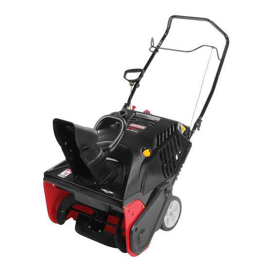
21" SNOW THROWER
Model No. 247.887802
CAUTION:
Before using this product,
read this manual
and follow
all safety
rules and operating
instructions.
• SAFETY
• ASSEMBLY
• OPERATION
• MAINTENANCE
•
PARTS LIST
•
ESPANOL
Sears Brands Management
Corporation,
Hoffman
Estates, IL 60179, U.S.A.
Visit our website:
www.craftsman.com
FormNo.769-06194G
(JuLy 18,2013)
Advertisement
Table of Contents

Related Manuals for Craftsman 247.887802


Summary of Contents for Craftsman 247.887802
- Page 1 Operator's Manual I:RRFrSMRN° 21" SNOW THROWER Model No. 247.887802 • SAFETY • ASSEMBLY • OPERATION • MAINTENANCE PARTS LIST • CAUTION: Before using this product, • ESPANOL read this manual and follow all safety rules and operating instructions. Sears Brands Management...
- Page 2 Parts List ..........Warranty Statement ........Safety Instructions ........Engine Parts List ........Labels ..........Assembly ..........Operation ........... Repair Protection Agreement ......Service and Maintenance ......Espa_ol ..........Service Numbers ......Back Cover Off-Season Storage ........Troubleshooting ........CRAFTSMAN TWO YEAR FULL WARRANTY FOR TWO YEARS f romthedateof purchase, this product i swarranted against a nydefects in material o r workmanship.
- Page 3 Thissymbolpointsout importantsafety instructionswhich, if not Thismachinewasbuilt to beoperatedaccordingto the safeoperation followed, could endangerthe personalsafetyand/or property of practicesin this manual.Aswith anytype of powerequipment, yourself and others.Readandfollow all instructions in this manual carelessness o r error on the part of the operatorcanresultin seriousinjury. beforeattempting to operatethis machine.Failureto complywith these Thismachineiscapableof amputating fingers, hands,toesandfeet and instructions m ay resultin personalinjury.Whenyou seethis symbol, HEED...
- Page 4 OPERATION CLEARING A CLOGGED DISCHARGE CHUTE Donot put hands or feetnearrotatingparts,inthe auger/impeller h ousing Hand contactwith the rotatingimpeller i nside the discharge c huteisthe most or chuteassembly. Contact w ith the rotatingpartscanamputatehands and common cause of injury associated w ith snowthrowers.Never u seyourhandto feet.
- Page 5 DO NOT MODIFY ENGINE Toavoidserious injuryor death,donot modify engineinanyway.Tampering with the governorsettingcanleadto arunaway engineandcauseit to operate at unsafespeeds. N evertamper with factorysetting of engine governor. NOTICE REGARDING EMiSSiONS Engines which are certified to complywith California andfederal EPA emissionregulations for SORE ( SmallOff RoadEquipment) a recertified tooperate on regularunleadedgasoline,and mayinclude the following emissioncontrol systems:Engine Modification (EM), O xidizingCatalyst ( 0C), Secondary Air injection(SAI) a ndThreeWayCatalyst ( TWC) i f soequipped.
- Page 6 SAFETY SYMBOLS Thispage depicts and describes safety symbols that may appear on this product. Read, understand, and follow all instructions on the machine before attempting to assemble and operate. READ THE OPERATOR'S MANUAL(S) Read, understand, and follow all instructions in the manual(s) before attempting to assemble operate WARNING--...
- Page 7 NOTE: Allreferences t o the left or right sideof thesnowthrowerarefrom the Tightenthe previously removed hardware to secure the handleinplace.See operator's position. A nyexceptions w ill be noted. Figure 2. Installing the Chute Unpacking the SnowThrower Place t he chutehandle on thelowerchuteasshowninFigure 3.Becertainthat Openthe top ofthe carton.
- Page 8 Alignthe holesinthe chutebasewith the holesinthe lowerchuteand Set-Up secure with the previously removed screws. S eeFigure 5. FuelRecommendations Operatingthe enginewith E15or E85fuel, an oil/gasoline mixture, dirty gasoline,or gasoline over 30 days old withoutfuel stabilizing additive may result in damageto your engine'scarburetor.Subsequent d amage would not be coveredunderthe manufacturer'swarranty.
- Page 9 Remove t he oil filler cap/dipstick. I fthe levelislow,slowlyaddoil untiloil Checking and Adding Oil levelregisters betweenhigh (H)andlow (L),Figure 8. Theengine isshipped without off in the engine.Youmustfii[ the engine with oil before operating. Runningthe engine with insufficient o il can causeseriousengine damageandvoid the productwarranty. Place thesnowthroweronaflat, levelsurface.
- Page 10 Electric Starter_ Recoil Button Electric S tarter _ ' Outlet GasCa ChuteAssembl' OilFill/ Choke L ever Electric Shave Figure 9 Recoil Starter I-lanolle Nowthat youhavesetupyoursnowthrower,it's importantto become acquainted with its controls andfeatures.Refer t o Figure 9. Therecoilstarterhandleisusedtostart the engine. ChokeControl GasCap Remove t he gascapto addfuel.
- Page 11 AugerControl Before Starting the Engine Located onthe upperhandle,the augercontrolhandleisusedto engage and disengage d riveto the auger.Squeeze t he control h andleagainst t he upperhandle Read,understandandfollow all the instructions a ndwarnings onthe to engage the auger;release it to disengage. machineand inthis manualbeforeoperating. ChuteAssembly Starting The Engine Rotatethe discharge c huteto the left or right usingthe controlhandle.
- Page 12 Electric Starter RecoilStarter Push the chokeleverto the CHOKEIJI position. Determine thatyourhome'swiring isathree-wiregrounded system. A skakensed electddanif youarenot certain. Ifthe engineiswarm,placethe chokeinthe RUN 1_ I positioninstead of CHOKEIJ 1. If youhaveagrounded three-prongreceptacle, proceed asfollows: Push the primerthree(3)times,makingsureto coverthevent holewhen pushing. Theextensioncordcanbe any length, but must be ratedfor 15 ampsat Ifthe engineiswarm,pushthe primerbuttononlyonce.
- Page 13 MAINTENANCE SCHEDULE Follow the maintenance schedule g ivenbelow. T his chartdescribes service guidelines only.Use the Service L ogcolumn tokeeptrackofcompleted maintenance tasks. T o Beforeperforming any type of maintenance/service, d isengageall controls schedule service from SearsParts & Repair, call 1-800-659-5917. andstop the engine.Wait untilall moving parts havecometo acomplete stop.Disconnect s parkplugwire andground it againstthe engine to prevent u nintended starting.
- Page 14 Remove t he threescrews thatsecure the lowerpanel.Remove t he lower Spar_ Plug panelbylifting up onthe panelto freethe tabsat the bottomof the panel fromthe tab slotsandthenpull back.SeeFigure 13. DONOT checkfor a sparkwith the sparkplug removed. D ONOT crankthe enginewith the sparkplug removed. If the engine hasbeenrunning,the muffler will beveryhot.Becareful not to touch the muffler.
- Page 15 Removing debris willinsure a dequate cooling, correct engine speed a ndreduce t he Measure the pluggapwith afeelergauge. C orrect asnecessary b ybending riskoffire. the sideelectrode, seeFigure 16.Thegapshouldbesetto .02-.03 inches (0.60-0.80 mm). Accumulationof debris aroundthe muffler couldcauseafire. Inspectand cleanbefore everyuse. Electrode Lubrication Lubricate the pivotpointsonthe controlhandleandthe extension springat the end of the control c ablewith a lightoil onceeveryseason andbefore the snowthrower...
- Page 16 If thestarterisdifficult to pull,remove the sparkplugandpullthe handle AugerDriveBelt Replacement several timesto ensure that anyoil trappedinthe engineheadis removed. Run the snowthroweruntil the fuel tank isempty. Pullthe recoil s tarterhandle until resistance i sfelt. Thentip the snow throwerbackuntil it restson the handles. Oil may comeout of the sparkplug holewhen it is removed and the starter handleispulled.
- Page 17 Toreplace the belt followtheseinstructions andreferto Figure 21: Tochange the rubberpaddles, p roceed asfollowsandreferto Figure 22: DrivePulle HexWasherScrew er Paddle BeJt K eel)e! HexWasher Screw Figure 21 Figure 22 Routethe beltaroundthe drivepulleyandunderthe idlerpulley. Run the snowthroweruntilthe fuel tankisempty. Routethe endofthe beltaroundthe augerpulleyandslidethe pulleyback Pullthe recoil s tarterhandleuntil resistance i sfelt.
- Page 18 If the snowthrowerwill not beusedfor30daysor longer, o r if it is theendof thesnowseason whenthe lastpossibility of snowisgone,the equipmentneeds to bestored properly.Follow storageinstructions belowto ensuretop performance f rom the snowthrowerformanymoreyears. Preparingsnow thrower Preparingthe engine Ifthe snowthrowerwill not beusedfor 30daysor longer, f ollowthe instructions Engines s toredover30daysneedto bedrained of fuel to prevent d eterioration and below.
- Page 19 Disconnect the sparkplug wireand groundit againstthe engineto prevent unintendedstarting. Beforeperforming anytypeof maintenance/service, disengage all controls andstopthe engine.Waituntil all movingparts havecome to acomplete stop.Alwayswearsafetyglasses duringoperation or while performing any adjustments or repairs. This section addresses minor service i ssues. Tolocate the nearest Sears Service Center orto schedule service, simply contact S ears at 1-800-4-MY-HOME Engine fails to start 1.
- Page 20 Single-Stage Snow Thrower-- Model No. 247.887802 ../44 ..........I \\34...
- Page 21 Single-Stage Snow Thrower-- Model No.247.887802 684-04168 946-04701 Clutch Cable Idler Pulley Assembly 684-04398- 747-05360A Drive Cable Wire Support Frame 4044 748-0234 Shoulder Spacer 684-04394 Auger Axle Assembly 749-04810 Lower Handle 684-04393 Auger Paddle 750-04571 Shoulder Spacer, .260 x .785 x .538 736-0343 Flat Washer, .330 x 1.250 x .120...
- Page 22 Single-Stage Snow Thrower-- Model No. 247.887802...
- Page 23 Single-Stage Snow Thrower-- Model No. 247.887802 710-0895 Screw, Y4-15x 0.75 710-0451 Carriage Bolt, %o-18 x .750 747-05327C- Auger Bail 0637 749- 04703B- Upper Handle 0637 712-04063 Flange Lock Nut, sA0-18 712-04064 Flange Lock Nut, 14-20 738-04419A Shoulder Screw, 1/4-20x .375 x .148...
- Page 24 CraftsmanEngine Model265JU-12 ForSnow Model247.887802 99 _7 Stud M8x36 710-04943 Bolt M6x28 710-04911 712-05015 NutM6 951-10657 Muffler Stud Assembly 951-12100 951-11289 Exhaust Pipe Gasket Governor Spring 951-10664 712-04214 Nut, M8 Throttle Linkage Spring 951-12010 951-10665 Throttle Linkage Muffler Assembly 710-04915 Bolt M6x12 951-11106 Governor 712-04212...
- Page 25 CraftsmanEngineModel265JU-12 ForSnow Model247.887802 ® ® ® 710-04974 Bolt M6xIO 710-04915 Bolt M6x12 951-12013 951-14152 Recoil Starter Ignition Coil Assembly 710-04919 Bolt M6x25 951-10645A Electric Starter 715-04088 Dowel Pin 8x8 951-12416 Flywheel 710-05182 Bolt M6x32 951-10934 Cooling 951-10911 710-04915 Bolt M6x12 Starter Cup 712-04209 951-11109...
- Page 26 CraftsmanEngine Model265JU-12 ForSnow Model247.887802 110-Complete Engine _'-76...
- Page 27 CraftsmanEngine Model 265JU-12 ForSnow Model 247.887802 710-04932 Bolt M8x32 951-I 1688 Piston Ring Set 951-I 1632 951-11283 Oil Filler Plug Assembly Piston Pin Snap Ring 951-I 1900 Piston 951-11577 O-Ring 15.8x2.5 951-I 1901 Piston Pin 951-11368 Oil Seal, 25x41.25x6 951-11913...
- Page 28 Craftsman Engine Model265JU-12 ForSnow Model247.887802 15 I_ 13--_ 108-Gasket Kit-Complete 109- Gasket Kit- External 110-Complete Engine...
- Page 29 CraftsmanEngine Model265JU-12 ForSnow Model247.887802 710-04933 Bolt M8x55 710-04968 Bolt M6x16 951-11054A Valve Cover 951-14195 Cylinder Head Assembly 951-12626 Valve Cover Kit (Incl. 6-17,19,22,26,28,39,43,44) 726-04101 951-10292 Breather Hose Clamp Spark Plug 951-11898 731-07059 Breather Hose Gasket, Cylinder Head 951-10648 Push Rod Kit 951-11565 Valve Cover Gasket 951-11892...
- Page 30 CraftsmanEngine Model265JU-12 For5now Model247.887802...
- Page 31 CraftsmanEngine Model 26SJU-12ForSnow Model 247.887802 Throttle Plate 710-05101 Stud M6x110 951-11567 Carburetor Insulator Gasket 710-05469 Screw M3x6 951-11568 Carburetor Insulator 736-04638 Lock Washer 951-11569A Carburetor Gasket Gasket, Throttle Plate 951-10639A Primer Assembly Idle Jet Assembly (0.34) 951-11824 Primer Bulb Idle Speed Adjusting...
- Page 32 CraftsmanSnowThrowerModel 247.887802 777S34027 777122139 777D16367 777S33731 777533118 777S32236 777D18416 777D18032 777123574...
- Page 33 Congratulations on making a smart purchase. Your new Craftsman® product is designed manufactured for years of dependable operation. But like all products, it may require repair from time to time. That's when having a Repair Protection Agreement can save you money and aggravation.
- Page 34 OWNERSWARRANTY RESPONSIBILITIES: As the outdoor equipment engine owner, you are responsible for performance of the required maintenance listed in your owner's manual. MTD Consumer Group Inc recommends that you retain all receipts covering maintenance on your outdoor equipment engine,...
- Page 35 Board m ay not b eused. The use ofany non-exempted add-on or modified parts b ytheultimate purchaser willbegrounds fordisallowing awarranty claims. MTD Consumer Group I nc willnotbeliable t o warrant failures ofwarranted parts c aused bytheuse ofanon-exempted add-on o rmodified part.
- Page 36 Declarad6n de garantia ......Almacenamiento fuera de temporada ....Medidas de seguridad ........ Solud6n de problemas ....... Montaje ..........Acuerdo de protecd6n para reparadones ..... Fundonamiento ........Numeros de servido ......Contratapa Servido y Mantenimiento ......CRAFTSMAN D OS ANOSDE6ARANTIA TOTAL Durante dosahosdesde lafechadecompra, esteproducto est_garantizado c ontracualquier d efecto demateriales o manodeobra.Unproducto defectuoso recibir_ la reparaci6n o sustituci6n gratuitasila reparaci6n n o est_disponible.
- Page 37 Estam_quinaest_ disefada para setutilizada respetandolasnormasde Lapresencia de este simboloindica quesetrata de instrucciones de seguridadcontenidasen este manual.AIigualqueconcualquiertipo de seguridadimportantes quedeberespetarparaevitar poneren riesgosu equipo motorizado, undescuidooerror por partedel operador puede seguridadpersonaly/o materialy la de losdem_is. L ea y cumpJa todasJas producir lesionesgraves.Estam_quinaescapazde amputar dedos,manos instrucciones de este manualantesde intentar operar esta m_iguina.
- Page 38 Manejo seguro de la gasolina: Sea sumamente p recavido cuando operelam_iquina sobreunasuperficie congravaocuando latruce.Mant#ngase a lertaporsisepresentan peligros Para evitarlesiones p ersona[es 0daffos materia[es sea sumamente c uidadoso ai ocultoso tr_nsito. manipu[ar [agaso[ina. La gaso[ina e ssumamente i nfiamab[e y sus vapores p ueden c ausar explosiones.
- Page 39 MANTENIMIENTO Y ALMACENAMIENTO NO MODIFIQUE EL MOTOR Nunca alterelosdispositivos d eseguridad. Controle peri6dicamente q ue Para evitarlesiones graves o lamuerte,no modifique el motorde ningunamanera. fundonencorrectamente. Rem[tase a lassecdones d emantenimiento y Si a lteralaconfiguraci6n delregulador, e l motorsepuede desbocar y fundonar ajustedeestemanual.
- Page 40 S|MBOLOS DE SEGURIDAD Enesta p_gina se presentan y describen los sirnboios de seguridad que pueden aparecer en este producto. Lea, entienda y curnpia todas [as [nstrucdones [nduidas en la rn_quina antes de [ntentar realizar el montaje de la unidad y utilizarla. LEA LOS MANUALES DEL OPERADOR Lea, entienda y cumpla todas las instrucciones incluidas en los manuales antes de realizar el montaje de la unidad y utilizarla.
- Page 41 Ajuste los elementos deferreteria q ue extrajo previamente para sujetar la NOTA: Todas l asreferencias a loslados derecho oizquierdo d elam_quina manija e nsulugar. Vea laFigura 2 . quitanieve sehacen observando lamismadesde laposid6ndeloperador. E ncaso de quehubiese unaexcepci6n, seespecificar_ c laramente. Instalad6n del canal C6mol)esembalarLaM_quinaQuitanieve Coloque e lconducto de lamanijaen larampainferiorcomosemuestra enla...
- Page 42 Alineelosorificiosde labase del canal c onlosorificiosdel canal i nferior y ConfiguYad6n suj_teloconlostornillosquee×trajo anteriormente. V ealaFigura 5. Recomendadonessobre el combustible El f uncionamiento delmotorconelcombustible E 15 oESS, unamezcla deaceite conlagasolina, l agasolina sucia, o lagasolina dem_sde30dias deedadque nohasidoaditivoestabilizador decombustible puederesultar e ndaffos al carburador desumotor.Da_os posteriores n oestarian cubiertos pot lagarantia delfabrkante.
- Page 43 Saque eltap6n/la varillademedid6nde aceite. S i e l nivelesbajo,agregue Procedimiento paracontrolar y agregar aceite lentamente aceitehastaqueelnivelregistrado est_en un puntointermedio entrealto (H)y bajo(L),Figura 8. Elmotor seenvia sinaceiteenel motor. Antesde ponerel motor en marcha debeIlenarlodeaceite.Si sehace funcionar el motor sinsuficiente aceite puedecausar d affos graves al motor y anularla garantiadelproducto. Coloque lam_quina quitanieveenunasuperficiefirmey nivelada.
- Page 44 Llave Manija del arrancadorde retroceso Palanca _d_ulador Tapade combustible Manijade Montaj_ de aceite Plata de raspado Barrena de retroceso Figura 9 Ahoraqueyahaajustado sum_quina quitanieve paraelfundonamiento, e s Manija del arrancadorde retroceso importante f amiliarizarse c onsuscontroles y caracteffsticas. Consulte laFigura 9. Lamanijadelarrancador de retroceso seutilizaparaencender e lmotor.
- Page 45 Controlde ia barrena Antesde arrancar el motor Lamanijade control d e labarrena est_ubicada enlabarrasuperior y seusa paraengranar y desengranar latransmisi6n d e labarrena. A prietelamanijade Lea,comprenday sigatodaslasinstrucciones y advertenciasqueaparecen control c ontralabarradecontrol s uperiorparaengranar l abarrena, a fl6jelapara en la m_quinayen este manualantesde hacerlafuncionar. desengranarla.
- Page 46 Bot6n del arrancador Arrancador de retroceso Determine si elcableado desuhogaresunsistemadetrescables conectado atierra. Empuje l apalanca d elestrangulador alaposid6n CHOKE (estrangulador)_J_. Consulte conunelectfidstamatficulado sinoest_seguro. Si e l motoryaest_caliente, u biqueel regulador e n laposici6n RUN (func ooam ento) I Den ugar de CHOKE (estrangu ador)H I Sicuentaconun recept_culo paratresparas conectado atierra,realicelossiguientes...
- Page 47 PEOGEAMA D EMANTENIMIENTO Siga el programa de mantenimiento a continuad6n. E sta tablasedescfiben las pautas deservicio solamente. U tilicela columna Registrode servk[o para Antes derealizar cualquier t ipodemantenimiento oservicio, desenga n cbetodos reaBzarun seguimiento de lastareas de mantenimiento reaBzadas. P ara loscontroles y detenga elmotor.Espere aquesedetengan completamente t odas programarel servido de SearsParts&...
- Page 48 Drene e [combustible deltanque hadendo fundonar el motor hasta que el Vuelvaacolocar eltap6nde vaciado y apri_telo firmemente. tanque d ecombustible est.1 r atio.Asecj@ese deque el tap6n deIlenado d e Rellene conelaceiterecomendado y compruebe e l niveldeaceite, c onsulte combustible esseguro. Comprobad6n y adid6ndeaceiteenlaSecd6n delaAsamblea.
- Page 49 La extracci6n delosresiduos asegura q ue elenfriamiento sea adecuado, lavelocidad Mida[aseparaci6n d ebujiaconunca[ibrador. R ea[ice l osajustesnecesarios delmotor c orrecta y elriesgo deincendio m enor. torciendo e[e[ectrodo lateral,Figura 16.Laseparaci6n d ebeajustarse en 0,02-0,03 pulgadas (0,60-0,80 mm). Laacumulaci6nde residuosairededordei silenciadorpodriaprodudr un incendio.
- Page 50 Siesdifidl jalar delarranque, extraigalabujiayjale delamanijavariasveces Reemplazode la ¢orrea de transmisi6n de la barrena paraestarsegurodequeseextralgacualquler c antidaddeaceiteatrapada Ponga en marcha lam_quina quitanievehastaqueeltanquedecombustible enlaculatadelmotor. est_vacio. Jaledelamanijadelarrancador de retroceso hastasentirresistenda. L uego inclinelam_qulna quitanlevehadaatr_shastaquequedeapoyada s obrelas Puede salir aceitedel orificio de la bujia cuandolamismaseextraeysejala manijas.
- Page 51 Para volveracolocar lacorrea sigaestasinstrucciones y consulte laFigura 21: Para cambiar l aspaletas decaucho, p roceda comosiguey consulte laFigura 22: /' / ! / Poleadetransmisi6r Polea loca Polea Tomillo paraarandela hexagonal barrena Fignra 21 Fignra 22 Pase lacorrea alrededor d e lapoleadetransmisi6n y pordebajo de lapolea Ponga en marcha la m_quina quitanievehastaqueeltanquede combustible loca.
- Page 52 Sinosevaa utilizarlam_quina quitanieve durante30diaso m_s,o sieselfinal delatemporada denievey yanoexisteposibilidad dequenieve,esnecesario a lmacenar elequipodemaneraadecuada. Sigalasinstrucciones d ealmacenamiento q ueseindicanacontinuaci6n paracjarantizar elrendimiento m_ximodelam_quina quitanieve durantemuchos afiosm_s. Preparaci6n de ia m quina quitanieve Preparaci6ndei motor SInosevaausar l am_quina q uitanieve durante 3 0d[as o m_s, siga lassiguientes Losmotores quesealmacenan durantem_sde30diasdebenserdrenados d e instrucdones incluidas a continuad6n.
- Page 53 Antesderealizarcualquier fipo de mantenimientooservicio, desenganche t odosloscontroles y detengaelmotor.Espere a quesedetengancompletamente todaslaspiezas m6viles.Desconecte elcabledelabujiay p6ngalohaciendo m asacontra elmotorparaevitarqueseencienda a cddentalmente. U tilice siempreanteojosdeseguridad duranteelfundonamientoo mientras ajustao repara este equipo. Enesta secd6n seanaiizan probiemasmenores de servkio. Paraubicarel CentrodeServkio Searsm_scercano o para programarun servkio, simplemente comuniquese con Sears ai tel_fono 1-800-4-MY-HOME °.
- Page 57 Felicitaciones por haber realizado una adquisici6n inteligente. El producto Craftsman® que ha adquirido esta diseSado y fabricado para brindar muchos aSos de funcionamiento confiable. Pero como todos los productos a veces puede requerir de reparaciones. Es en ese momento cuando disponer de un Acuerdo de protecci6n...
- Page 58 Agencia de Proteccidn Medioambiental de los Estados Unidos, (EPA). MTD Consumer Group Inc. debe garantizar el sistema de control de emisiones (ECS) de su motor de equipos de exteriores por el periodo...
- Page 59 (Air R esources Board). El u so decualquier pieza a dicional omodificada noexenta pot e lcomprador final s er_ c ausal deinvalidez delos reclamos bajo garantia. MTD Consumer Group I nc notendr_ r esponsabilidad potlagarantia defallas d epiezas garantizadas que fueren causadas pot e luso deuna pieza a dicional noexenta omodificada.
- Page 60 Your Home For troubleshooting, product manuals and expert advice: managernylife www.managemylife.com For repair - in your home - of all major brand appliances, lawn and garden equipment, or heating and cooling systems, no matter who made it, no matter who sold it! For the replacement parts, accessories owner's manuals that you need to do-it-yourself.
Need help?
Do you have a question about the 247.887802 and is the answer not in the manual?
Questions and answers