Table of Contents
Advertisement
Available languages
Available languages
Operator's Manual
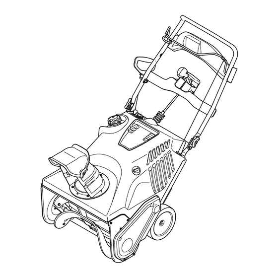
21" SNOW THROWER
Model No. 247.88782
CAUTION: Before using
this product, read this
manual and follow all
safety rules and operating
instructions.
Sears Brands Management Corporation, Hoffman Estates, IL 60179, U.S.A.
®
Visit our website: www.craftsman.com
• SAFETY
• ASSEMBLY
• OPERATION
• MAINTENANCE
• PARTS LIST
• ESPAÑOL
FORM NO. 769-07096
6/1/2011
Advertisement
Table of Contents

Related Manuals for Craftsman 31AM2T6D799


Summary of Contents for Craftsman 31AM2T6D799
- Page 1 • MAINTENANCE • PARTS LIST CAUTION: Before using • ESPAÑOL this product, read this manual and follow all safety rules and operating instructions. Sears Brands Management Corporation, Hoffman Estates, IL 60179, U.S.A. FORM NO. 769-07096 Visit our website: www.craftsman.com 6/1/2011...
-
Page 2: Table Of Contents
This warranty is void if this product is ever used while providing commercial services or if rented to another person. For warranty coverage details to obtain repair or replacement, visit the web site: www.craftsman.com This warranty covers ONLY defects in material and workmanship. Warranty coverage does NOT include: •... -
Page 3: Safe Operation Practices
SAFETY INSTRUCTIONS WARNING DANGER This machine was built to be operated according to the safe opera- This symbol points out important safety instructions which, if not tion practices in this manual. As with any type of power equipment, followed, could endanger the personal safety and/or property of carelessness or error on the part of the operator can result in serious yourself and others. - Page 4 SAFETY INSTRUCTIONS Safe Handling of Gasoline • Exercise extreme caution when operating on or crossing gravel surfaces. Stay alert for hidden hazards or traffic. To avoid personal injury or property damage use extreme care in handling gasoline. Gasoline is extremely flammable and the vapors are •...
- Page 5 SAFETY INSTRUCTIONS MAINTENANCE & STORAGE DO NOT MODIFY ENGINE • Never tamper with safety devices. Check their proper operation To avoid serious injury or death, do not modify engine in any way. regularly. Refer to the maintenance and adjustment sections of Tampering with the governor setting can lead to a runaway engine and this manual.
- Page 6 SAFETY INSTRUCTIONS SAFETY SYMBOLS This page depicts and describes safety symbols that may appear on this product. Read, understand, and follow all instructions on the machine before attempting to assemble and operate. Symbol Description READ THE OPERATOR’S MANUAL(S) Read, understand, and follow all instructions in the manual(s) before attempting to assemble and operate WARNING—...
-
Page 7: Assembly
ASSEMBLY NOTE: All references to the left or right side of the snow thrower are Pivot the upper handle into the operating position. Be sure not to from the operator’s position. Any exceptions will be noted. pinch any of the cables in the process. See Figure 2. UNPACKING THE SNOW THROWER Open the top of the carton. - Page 8 ASSEMBLY Installing the Chute Installing the Chute Rotation Control Assembly Remove the hex washer screws in the chute base. See Figure 4. Remove the four hex washer screws from the back of the handle (two on each side). See Figure 6. Hex Washer Screw Figure 4...
- Page 9 ASSEMBLY Installing the Recoil Starter Handle Remove the screw and hex lock nut from the universal joint. See Figure 8. Remove the eye bolt and handle knob from the manual bag. Place the eye bolt and handle knob on the upper handle as shown in Figure 10.
- Page 10 ASSEMBLY WARNING Always keep hands and feet clear of equipment moving parts. Do not use a pressurized starting fluid. Vapors are flammable. Remove the gas cap, check the fuel level and add fuel if necessary. Fill the tank until the fuel reaches 1/2” below the bottom of the filler neck to allow for fuel expansion.
-
Page 11: Operation
GAS CAP MUFFLER Remove the gas cap to add fuel. Engine exhaust exits the engine via the muffler. Meets ANSI Safety Standards Craftsman Snow Throwers conform to the safety standard of the American National Standards Institute (ANSI). - Page 12 OPERATION CHUTE ROTATION CONTROL Insert ignition key into slot. Make sure it snaps into place. Do not attempt to turn the key. See Figure 13. The chute rotate control is located in the center of the control panel and controls the direction snow is thrown. Depress the button and rotate the chute rotation control to the right to turn the chute to the right and rotate to the left to turn the chute to the left.
- Page 13 OPERATION STOPPING THE ENGINE Push the choke lever to the CHOKE position. Run the engine for a few minutes without load before stopping to If the engine is warm, place the choke in the RUN position help dry off any moisture on the engine. To stop the engine remove the key and store it in a safe place.
-
Page 14: Service And Maintenance
SERVICE AND MAINTENANCE MAINTENANCE SCHEDULE WARNING Before performing any type of maintenance/service, disengage all Follow the maintenance schedule given below. This chart describes controls and stop the engine. Wait until all moving parts have come service guidelines only. Use the Service Log column to keep track of to a complete stop. - Page 15 SERVICE AND MAINTENANCE Drain fuel from the tank by running the engine until the fuel tank is Refill with the recommended oil and check the oil level; refer to empty. Be sure the fuel fill cap is secure. Checking and Adding Oil in the Assembly Section. Remove the three screws that secure the lower panel.
- Page 16 SERVICE AND MAINTENANCE Measure the plug gap with a feeler gauge. Correct as necessary Removing debris will insure adequate cooling, correct engine speed by bending the side electrode, Figure 19. The gap should be set and reduce the risk of fire. to .02-.03 inches (0.60-0.80 mm).
- Page 17 SERVICE AND MAINTENANCE AUGER DRIVE BELT REPLACEMENT Tip the snow thrower back to the operating position and pull the starter handle a few times to see if it is difficult to pull. Run the snow thrower until the fuel tank is empty. If the starter is difficult to pull, remove the spark plug and pull the Pull the recoil starter handle until resistance is felt.
- Page 18 SERVICE AND MAINTENANCE To replace the belt follow these instructions and refer to Figure 24: To change the rubber paddles, proceed as follows and refer to Figure Drive Pulley Idler Pulley Hex Washer Screw Auger Paddle Belt Keeper Flange Nut Auger Pulley Hex Washer Screw Figure 24...
-
Page 19: Off-Season Storage
OFF-SEASON STORAGE If the snow thrower will not be used for 30 days or longer, or if it is the end of the snow season when the last possibility of snow is gone, the equipment needs to be stored properly. Follow storage instructions below to ensure top performance from the snow thrower for many more years. PREPARING THE ENGINE PREPARING SNOW THROWER If the snow thrower will not be used for 30 days or longer, follow the... -
Page 20: Troubleshooting
TROUBLESHOOTING WARNING Before performing any type of maintenance/service, disengage all controls and stop the engine. Wait until all moving parts have come to a complete stop. Disconnect spark plug wire and ground it against the engine to prevent unintended starting. Always wear safety glasses during operation or while performing any adjustments or repairs. - Page 21 NOTES This page intentionally left blank. Use this page to make any notes regarding your snow thrower.
-
Page 22: Parts List
PARTS LIST Craftsman Snow Thrower Model 247.88782... - Page 23 PARTS LIST Craftsman Snow Thrower Model 247.88782 Ref. No. Part No. Description Ref. No. Part No. Description 684-04168 Idler Pulley Assembly 750-04571 Shoulder Spacer 984-04393 Auger Assembly 790-00426-0637 Idler Cable Bracket — 753-06469 Rubber Auger Paddle Kit (Includes 2 790-00444-4044 RH Side Plate...
- Page 24 PARTS LIST Craftsman Snow Thrower Model 247.88782...
- Page 25 PARTS LIST Craftsman Snow Thrower Model 247.88782 Ref. No. Part No. Description Ref. No. Part No. Description 631-04526P Chute Rotation Control Assembly 631-04504 Handle Panel 684-04350 Joint Block Assembly — 777X44559 Light Label 684-04383-0637 Indicator Bracket Assembly 710-04998 Carriage Screw, 5/16-18 x 1.00 710-0451 Carriage Bolt, 5/16-18 x .750...
-
Page 26: Labels
PARTS LIST Craftsman Snow Thrower Model 247.88782 777S34027 777I22139 STARTING STOP INSTRUCTIONS: 1.) INSERT IGNITION KEY AND SNAP IN PLACE. 1.KEEP AWAY FROM ROTATING 2.) MOVE CHOKE CONTROL TO THE AUGER CONTACT WITH AUGER “CHOKE” POSITION. PUSH PRIMER Do not use electric start in the rain BUTTON 3x. - Page 27 NOTES This page intentionally left blank. Use this page to make any notes regarding your snow thrower.
- Page 28 MTD CONSUMER GROUP (MTD), the California Air Resources Board (CARB) and the United States Environment Protection Agency (U. S. EPA) Emission Control System Warranty Statement (Owner’s Defect Warranty Rights and Obligations) EMISSION CONTROL SYSTEM COVERAGE IS APPLICABLE TO CERTIFIED ENGINES PURCHASED IN CALIFORNIA IN 2005 AND THERE- AFTER, WHICH ARE USED IN CALIFORNIA, AND TO CERTIFIED MODEL YEAR 2005 AND LATER ENGINES WHICH ARE PURCHASED AND USED ELSEWHERE IN THE UNITED STATES.
- Page 29 (4) Repair or replacement of any warranted part under the warranty provisions of this article must be performed at no charge to the owner at a warranty station. (5) Notwithstanding the provisions of Subsection (4) above, warranty services or repairs must be provided at all MTD distribution centers that are franchised to service the subject engines.
- Page 30 Look For Relevant Emissions Durability Period and Air Index Information On Your Engine Emissions Label Engines that are certified to meet the California Air Resources Board (CARB) Tier 2 Emission Standards must display information regarding the Emissions Durability Period and the Air Index. Sears Brands Management Corporation makes this information available to the consumer on our emission labels.
-
Page 31: Repair Protection Agreement
REPAIR PROTECTION AGREEMENT Congratulations on making a smart purchase. Your new Craftsman® product is designed and manufactured for years of dependable operation. But like all products, it may require repair from time to time. That’s when having a Repair Protection Agreement can save you money and aggravation. -
Page 32: Español
La presente garantía se anula si se utiliza este producto alguna vez para prestar servicios comerciales o si se lo alquila a otra persona. Para obtener información sobre el alcance de la garantía y solicitar la reparación o el reemplazo, visite el sitio Web: www.craftsman.com Esta garantía cubre ÚNICAMENTE los defectos en los materiales y en la mano de obra. - Page 33 INSTRUCCIONES DE SEGURIDAD ADVERTENCIA PELIGRO Esta máquina está diseñada para ser utilizada respetando las normas La presencia de este símbolo indica que se trata de instrucciones de de seguridad contenidas en este manual. Al igual que con cualquier tipo seguridad importantes que debe respetar para evitar poner en riesgo su de equipo motorizado, un descuido o error por parte del operador puede seguridad personal y/o material y la de los demás.
- Page 34 INSTRUCCIONES DE SEGURIDAD Manejo seguro de la gasolina • Planifique el patrón en el que va a ir arrojando nieve para evitar que la descarga de material se produzca hacia las ventanas, las paredes, Para evitar lesiones personales o daños materiales sea sumamente cuida- los automóviles, etc.
- Page 35 INSTRUCCIONES DE SEGURIDAD MANTENIMIENTO Y ALMACENAMIENTO NO MODIFIQUE EL MOTOR • Nunca altere los dispositivos de seguridad. Controle periódicamente que Para evitar lesiones graves o la muerte, no modifique el motor de ninguna funcionen correctamente. Remítase a las secciones de mantenimiento y manera.
- Page 36 INSTRUCCIONES DE SEGURIDAD SÍMBOLOS DE SEGURIDAD En esta página se presentan y describen los símbolos de seguridad que pueden aparecer en este producto. Lea, entienda y cumpla todas las instrucciones incluidas en la máquina antes de intentar realizar el montaje de la unidad y utilizarla. Símbolo Descripción LEA LOS MANUALES DEL OPERADOR...
- Page 37 MONTAJE NOTA: Todas las referencias a los lados derecho o izquierdo de la Gire la manija superior a la posición de funcionamiento. Asegúrese máquina quitanieve se hacen observando la misma desde la posición de no apretar los cables en el proceso. Vea la Figura 2. del operador.
- Page 38 MONTAJE Instalación del canal Instalación del montaje del control de rotación del canal Extraiga los tornillos de cabeza hexagonal de la base del canal. Vea la Figura 4. Extraiga los cuatro tornillos de cabeza hexagonal de la parte posterior de la manija (dos a cada lado). Vea la Figura 6. Tornillo de cabeza hexagonal...
- Page 39 MONTAJE Instalación de la manija del arrancador 11. Retire el tornillo y la tuerca hexagonal de la junta universal. Vea la Figura 8. de retroceso Retire el perno de ojo y la perilla de la manija de la bolsa del manual.
- Page 40 MONTAJE • Evite el contacto repetido o prolongado con la piel y la inhalación Saque el tapón / la varilla de medición de aceite. Si el nivel es de los vapores. bajo, agregue lentamente aceite hasta que el nivel registrado esté en un punto intermedio entre alto (H) y bajo (L), Figura 11.
- Page 41 La manija del arrancador de retroceso se utiliza para encender el motor. Cumple con los estándares de seguridad de ANSI Las máquinas quitanieve Craftsman cumplen con los estándares de seguridad del Instituto Estadounidense de Estándares Nacionales (ANSI).
- Page 42 FUNCIONAMIENTO SILENCIADOR Inserte la llave de encendido en la ranura. Asegúrese de que entre a presión en su lugar. No intente girar la llave. Vea la Figura 13. El escape del motor sale del motor a través del silenciador. CONTROL DE ROTACIÓN DEL CANAL El control de rotación del canal está...
- Page 43 FUNCIONAMIENTO DETENCIÓN DEL MOTOR Empuje la palanca del cebador a la posición CHOKE (cebador) Haga funcionar el motor durante unos minutos sin carga antes de Si el motor ya está caliente, ubique el cebador en la posición parar para ayudar a secar la humedad en el motor. RUN (funcionamiento) en lugar de CHOKE (cebador) Para detener el motor saque la llave y guárdela en un lugar...
- Page 44 SERVICIO Y MANTENIMIENTO PROGRAMA DE MANTENIMIENTO ADVERTENCIA Antes de realizar cualquier tipo de mantenimiento o servicio, de- Siga el cronograma de mantenimiento que se presenta a continuación. senganche todos los controles y detenga el motor. Espere a que se Esta tabla sólo describe pautas de servicio. Utilice la columna Registro detengan completamente todas las piezas móviles.
- Page 45 SERVICIO Y MANTENIMIENTO Vacíe el combustible del depósito haciendo funcionar el motor Incline la máquina quitanieve hacia atrás para drenar el aceite en hasta que el depósito de combustible esté vacío. Cerciórese de el recipiente. El aceite usado se debe descartar en un centro de que el tapón de llenado del combustible está...
- Page 46 SERVICIO Y MANTENIMIENTO Mida la separación de bujía con un calibrador. Realice los ajustes La extracción de los residuos asegura que el enfriamiento sea adec- necesarios torciendo el electrodo lateral, Figura 19. La separación uado, la velocidad del motor correcta y el riesgo de incendio menor. debe ajustarse en 0,02-0,03 pulgadas (0,60-0,80 mm).
- Page 47 SERVICIO Y MANTENIMIENTO Cable de control Afloje los cuatro tuercas y los tornillos de bloqueo de transporte que sujetan la placa de afeitar a la vivienda. Consulte la Figura 20. Es posible que necesite realizar ajustes periódicos debido al estiramien- Mueva el afeitado placa en la posición adecuada y vuelva a apretar to del cable de control y de la correa de transmisión ocasionado por el las tuercas y los tornillos.
- Page 48 SERVICIO Y MANTENIMIENTO REEMPLAZO DE LA CORREA Extraiga la polea de la barrena y la correa. DE TRANSMISIÓN DE LA BARRENA Para volver a colocar la correa siga estas instrucciones y consulte la Figura 24: Ponga en marcha la máquina quitanieve hasta que el tanque de combustible esté...
- Page 49 SERVICIO Y MANTENIMIENTO REEMPLAZO DE LAS PALETAS REEMPLAZO O REVERSO DE LA PLACA DE DE LA BARRENA RASPADO La placa de raspado está adosada al fondo de la caja de la barrena Las paletas de caucho de la barrena de la máquina quitanieve se y sujeta a desgaste.
- Page 50 ALMACENAMIENTO FUERA DE TEMPORADA Si no se va a utilizar la máquina quitanieve durante 30 días o más, o si es el final de la temporada de nieve y ya no existe posibilidad de que nieve, es necesario almacenar el equipo de manera adecuada. Siga las instrucciones de almacenamiento que se indican a continuación para garantizar el rendimiento máximo de la máquina quitanieve durante muchos años más.
- Page 51 SOLUCIÓN DE PROBLEMAS ADVERTENCIA Antes de realizar cualquier tipo de mantenimiento o servicio, desenganche todos los controles y detenga el motor. Espere a que se detengan completamente todas las piezas móviles. Desconecte el cable de la bujía y póngalo haciendo masa contra el motor para evitar que se encienda accidentalmente.
- Page 52 MTD CONSUMER GROUP, INC. (MTD), el Bordo de Recursos de Aire de California (CARB) y la Agencia de Protección Medioambiental de Estados Unidos (U. S. EPA) Declaración de Garantía del Sistema de Control de Emisiones (Derechos y obligaciones del propietario según la garantía contra defectos) LA COBERTURA DE SISTEMA DE CONTROL DE EMISIÓN ES APLICABLE A MOTORES CERTIFICADOS COMPRADOS EN CALIFORNIA EN 2005 Y A PARTIR DE ENTONCES, QUE SON USADOS EN CALIFORNIA, Y HASTA AÑO 2005 DE MODELO CERTIFICADO Y MOTORES POSTERIORES QUE SON COMPRADOS Y USADOS EN OTRA PARTE EN LOS ESTADOS UNIDOS.
- Page 53 reemplazada según la garantía se garantizará por el resto del período de garantía. Cualquier pieza garantizada que esté programada para reemplazo según el mantenimiento requerido de conformidad con las instruc- ciones escritas de la Subsección (c) se garantiza por el período de tiempo anterior a la primera fecha de reemplazo programada para esa pieza.
- Page 54 Busque el período de duración de emisiones importantes yla información de clasificación de aire en la etiqueta de emisiones de su motor Los motores cuyo cumplimiento con los estándares de emisión Tier 2 de la Comisión de Recursos Ambientales de California (CARB) esté...
- Page 55 ACUERDO DE PROTECCIÓN PARA REPARACIONES Felicitaciones por haber realizado una adquisición inteligente. El producto Craftsman® que ha adquirido está diseñado y fabricado para brindar muchos años de funcionamiento confiable. Pero como todos los productos a veces puede requerir de reparaciones. Es en ese momento cuando el disponer de un Acuerdo de protección para reparaciones le puede ahorrar dinero y problemas.
- Page 56 Get it fixed, at your home or ours! Your Home For troubleshooting, product manuals and expert advice: www.managemylife.com For repair – in your home – of all major brand appliances, lawn and garden equipment, or heating and cooling systems, no matter who made it, no matter who sold it! For the replacement parts, accessories and owner’s manuals that you need to do-it-yourself.
Need help?
Do you have a question about the 31AM2T6D799 and is the answer not in the manual?
Questions and answers