Table of Contents
Advertisement
Available languages
Available languages
Quick Links
Operator's Manual
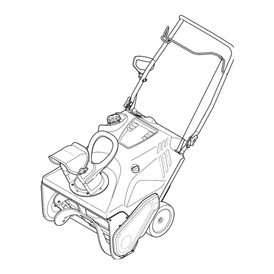
21" SNOW THROWER
Model No. 247.887801
CAUTION: Before using
this product, read this
manual and follow all
safety rules and operating
instructions.
Sears Brands Management Corporation, Hoffman Estates, IL 60179, U.S.A.
®
Visit our website: www.craftsman.com
• SAFETY
• ASSEMBLY
• OPERATION
• MAINTENANCE
• PARTS LIST
• ESPAÑOL
FORM NO. 769-06194F
7/19/2012
Advertisement
Table of Contents

Related Manuals for Craftsman 247.887801


Summary of Contents for Craftsman 247.887801
- Page 1 Operator’s Manual ® 21” SNOW THROWER Model No. 247.887801 • SAFETY • ASSEMBLY • OPERATION • MAINTENANCE • PARTS LIST CAUTION: Before using • ESPAÑOL this product, read this manual and follow all safety rules and operating instructions. Sears Brands Management Corporation, Hoffman Estates, IL 60179, U.S.A.
-
Page 2: Table Of Contents
This warranty is void if this product is ever used while providing commercial services or if rented to another person. For warranty coverage details to obtain repair or replacement, visit the web site: www.craftsman.com This warranty covers ONLY defects in material and workmanship. Warranty coverage does NOT include: •... - Page 3 SAFETY INSTRUCTIONS WARNING DANGER This machine was built to be operated according to the safe opera- This symbol points out important safety instructions which, if not tion practices in this manual. As with any type of power equipment, followed, could endanger the personal safety and/or property of carelessness or error on the part of the operator can result in serious yourself and others.
- Page 4 SAFETY INSTRUCTIONS Safe Handling of Gasoline • Exercise extreme caution when operating on or crossing gravel surfaces. Stay alert for hidden hazards or traffic. To avoid personal injury or property damage use extreme care in handling gasoline. Gasoline is extremely flammable and the vapors are •...
- Page 5 SAFETY INSTRUCTIONS MAINTENANCE & STORAGE DO NOT MODIFY ENGINE • Never tamper with safety devices. Check their proper operation To avoid serious injury or death, do not modify engine in any way. regularly. Refer to the maintenance and adjustment sections of Tampering with the governor setting can lead to a runaway engine and this manual.
- Page 6 SAFETY INSTRUCTIONS SAFETY SYMBOLS This page depicts and describes safety symbols that may appear on this product. Read, understand, and follow all instructions on the machine before attempting to assemble and operate. Symbol Description READ THE OPERATOR’S MANUAL(S) Read, understand, and follow all instructions in the manual(s) before attempting to assemble and operate WARNING—...
-
Page 7: Assembly
ASSEMBLY NOTE: All references to the left or right side of the snow thrower are Tighten the previously removed hardware to secure the handle in from the operator’s position. Any exceptions will be noted. place. See Figure 2. UNPACKING THE SNOW THROWER Installing the Chute Place the chute handle on the lower chute as shown in Figure 3. - Page 8 ASSEMBLY SET-UP Align the holes in the chute base with the holes in the lower chute and secure with the previously removed screws. See Figure 5. Fuel Recommendations Use automotive gasoline (unleaded or low leaded to minimize combus- tion chamber deposits) with a minimum of 87 octane. Gasoline with up to 10% ethanol or 15% MTBE (Methyl Tertiary Butyl Ether) can be used.
- Page 9 ASSEMBLY Checking and Adding Oil Remove the oil filler cap/dipstick. If the level is low, slowly add oil until oil level registers between high (H) and low (L), Figure 8. CAUTION The engine is shipped without oil in the engine. You must fill the engine with oil before operating.
-
Page 10: Operation
Pressing the primer, making sure to cover the the pavement. vent hole when pushing, forces fuel directly into the engine’s carburetor to aid in cold-weather starting. Meets ANSI Safety Standards Craftsman Snow Throwers conform to the safety standard of the American National Standards Institute (ANSI). - Page 11 OPERATION AUGER CONTROL BEFORE STARTING THE ENGINE Located on the upper handle, the auger control handle is used to WARNING engage and disengage drive to the auger. Squeeze the control handle Read, understand and follow all the instructions and warnings on the against the upper handle to engage the auger;...
- Page 12 OPERATION Electric Starter Recoil Starter Determine that your home’s wiring is a three-wire grounded system. Push the choke lever to the CHOKE position. Ask a licensed electrician if you are not certain. If the engine is warm, place the choke in the RUN position If you have a grounded three-prong receptacle, proceed as follows: Plug the extension cord into the outlet located on the engine’s...
-
Page 13: Service And Maintenance
SERVICE AND MAINTENANCE MAINTENANCE SCHEDULE WARNING Before performing any type of maintenance/service, disengage all Follow the maintenance schedule given below. This chart describes controls and stop the engine. Wait until all moving parts have come service guidelines only. Use the Service Log column to keep track of completed maintenance tasks. - Page 14 SERVICE AND MAINTENANCE Drain fuel from the tank by running the engine until the fuel tank is Refill with the recommended oil and check the oil level; refer to empty. Be sure the fuel fill cap is secure. Checking and Adding Oil in the Assembly Section. Remove the three screws that secure the lower panel.
- Page 15 SERVICE AND MAINTENANCE Measure the plug gap with a feeler gauge. Correct as necessary Removing debris will insure adequate cooling, correct engine speed by bending the side electrode, Figure 16. The gap should be set and reduce the risk of fire. to .02-.03 inches (0.60-0.80 mm).
- Page 16 SERVICE AND MAINTENANCE AUGER DRIVE BELT REPLACEMENT If the starter is difficult to pull, remove the spark plug and pull the handle several times to ensure that any oil trapped in the engine Run the snow thrower until the fuel tank is empty. head is removed.
- Page 17 SERVICE AND MAINTENANCE To replace the belt follow these instructions and refer to Figure 21: To change the rubber paddles, proceed as follows: Drive Pulley Idler Pulley Hex Washer Screw Auger Paddle Belt Keeper Flange Nut Auger Pulley Hex Washer Screw Figure 21 Figure 22 Route the belt around the drive pulley and under the idler pulley.
-
Page 18: Off-Season Storage
OFF-SEASON STORAGE If the snow thrower will not be used for 30 days or longer, or if it is the end of the snow season when the last possibility of snow is gone, the equipment needs to be stored properly. Follow storage instructions below to ensure top performance from the snow thrower for many more years. PREPARING THE ENGINE PREPARING SNOW THROWER If the snow thrower will not be used for 30 days or longer, follow the... -
Page 19: Troubleshooting
TROUBLESHOOTING WARNING Before performing any type of maintenance/service, disengage all controls and stop the engine. Wait until all moving parts have come to a complete stop. Disconnect spark plug wire and ground it against the engine to prevent unintended starting. Always wear safety glasses during operation or while performing any adjustments or repairs. -
Page 20: Parts List
PARTS LIST Craftsman Snow Thrower Model 247.887801 22 36... - Page 21 PARTS LIST Craftsman Snow Thrower Model 247.887801 Ref. No. Part No. Description Ref. No. Part No. Description 684-04168 Idler Pulley Assembly 946-04701 Clutch Cable 684-04398-4044 Frame 747-05360A Drive Cable Wire Support 684-04394 Auger Axle Assembly 748-0234 Shoulder Spacer — 684-04393...
- Page 22 PARTS LIST Craftsman Snow Thrower Model 247.887801...
- Page 23 PARTS LIST Craftsman Snow Thrower Model 247.887801 Ref. No. Part No. Description 710-0895 Screw, 1/4-15 x 0.75 710-0451 Carriage Bolt, 5/16-18 x .750 747-05327C-0637 Auger Bail 749-04703B-0637 Upper Handle 712-04063 Flange Lock Nut, 5/16-18 712-04064 Flange Lock Nut, 1/4-20 738-04419A Shoulder Screw, 1/4-20 x .375 x .148...
- Page 24 PARTS LIST Craftsman Engine Model 265-JU-12 For Snow Model 247.887801 Ref. Part No. Description Ref. Part No. Description 710-04943 Bolt M6×28 710-04911 Stud M8×36 712-05015 Nut M6 951-10657 Muffler Stud Assembly 951-12100 Governor Spring 951-11289 Exhaust Pipe Gasket 712-04214 Nut, M8...
- Page 25 PARTS LIST Craftsman Engine Model 265-JU-12 For Snow Model 247.887801 Ref. Part No. Description Ref. Part No. Description 710-04974 Bolt M6×10 710-04915 Bolt M6×12 951-14152 Recoil Starter 951-12013 Ignition Coil Assembly 951-10645A Electric Starter 710-04919 Bolt M6×25 715-04088 Dowel Pin 8×8...
- Page 26 PARTS LIST Craftsman Engine Model 265-JU-12 For Snow Model 247.887801 108 - Gasket Kit - Complete 109 - Gasket Kit - External 110 - Complete Engine...
- Page 27 PARTS LIST Craftsman Engine Model 265-JU-12 For Snow Model 247.887801 Ref. Part No. Description Ref. Part No. Description 710-04932 Bolt M8×32 951-11688 Piston Ring Set 951-11632 Piston Pin Snap Ring 951-11283 Oil Filler Plug Assembly 951-11577 O-Ring 15.8×2.5 951-11900 Piston 951-11368 Oil Seal, 25×41.25×6...
- Page 28 PARTS LIST Craftsman Engine Model 265-JU-12 For Snow Model 247.887801 42 42 108 - Gasket Kit - Complete 109 - Gasket Kit - External 110 - Complete Engine...
- Page 29 PARTS LIST Craftsman Engine Model 265-JU-12 For Snow Model 247.887801 Ref. Part No. Description Ref. Part No. Description 710-04933 Bolt M8×55 710-04968 Bolt M6×16 951-14195 Cylinder Head Assembly 951-11054A Valve Cover (Incl. 6-17,19,22,26,28,39,43,44) 951-12626 Valve Cover Kit 951-10292 Spark Plug...
- Page 30 PARTS LIST Craftsman Engine Model 265-JU-12 For Snow Model 247.887801 111 - Carburetor Kit...
- Page 31 PARTS LIST Craftsman Engine Model 265-JU-12 For Snow Model 247.887801 Ref. Part No. Description Ref. Part No. Description Throttle Plate 710-05101 Stud M6×110 710-05469 Screw M3×6 951-11567 Carburetor Insulator Gasket 736-04638 Lock Washer 951-11568 Carburetor Insulator Gasket, Throttle Plate 951-11569A Carburetor Gasket Idle Jet Assembly (0.34)
- Page 32 PARTS LIST Craftsman Snow Thrower Model 247.887801 777S34027 STARTING STOP INSTRUCTIONS: 1.) INSERT IGNITION KEY AND SNAP IN PLACE. 2.) MOVE CHOKE CONTROL TO THE “CHOKE” POSITION. PUSH PRIMER BUTTON 3x. 1.KEEP AWAY FROM ROTATING ROPE START: PULL SLOWLY UNTIL HARDER...
- Page 33 NOTES...
- Page 34 MTD CONSUMER GROUP INC (MTD), the California Air Resources Board (CARB) and the United States Environment Protection Agency (U. S. EPA) Emission Control System Warranty Statement (Owner’s Defect Warranty Rights and Obligations) EMISSION CONTROL SYSTEM COVERAGE IS APPLICABLE TO CERTIFIED ENGINES PURCHASED IN CALIFORNIA IN 2005 AND THERE- AFTER, WHICH ARE USED IN CALIFORNIA, AND TO CERTIFIED MODEL YEAR 2005 AND LATER ENGINES WHICH ARE PURCHASED AND USED ELSEWHERE IN THE UNITED STATES.
- Page 35 (6) The owner must not be charged for diagnostic labor that leads to the determination that a warranted part is in fact defective, provided that such diagnostic work is performed at a warranty station. (7) The engine manufacturer is liable for damages to other engine components proximately caused by a failure under warranty of any warranted part.
-
Page 36: Labels
Look For Relevant Emissions Durability Period and Air Index Information On Your Engine Emissions Label Engines that are certified to meet the California Air Resources Board (CARB) Tier 2 Emission Standards must display information regarding the Emissions Durability Period and the Air Index. Sears Brands Management Corporation makes this information available to the consumer on our emission labels. -
Page 37: Repair Protection Agreement
REPAIR PROTECTION AGREEMENT Congratulations on making a smart purchase. Your new Craftsman® product is designed and manufactured for years of dependable operation. But like all products, it may require repair from time to time. That’s when having a Repair Protection Agreement can save you money and aggravation. - Page 38 La presente garantía se anula si se utiliza este producto alguna vez para prestar servicios comerciales o si se lo alquila a otra persona. Para obtener información sobre el alcance de la garantía y solicitar la reparación o el reemplazo, visite el sitio Web: www.craftsman.com Esta garantía cubre ÚNICAMENTE los defectos en los materiales y en la mano de obra.
- Page 39 INSTRUCCIONES DE SEGURIDAD ADVERTENCIA PELIGRO Esta máquina está diseñada para ser utilizada respetando las normas La presencia de este símbolo indica que se trata de instrucciones de de seguridad contenidas en este manual. Al igual que con cualquier tipo seguridad importantes que debe respetar para evitar poner en riesgo su de equipo motorizado, un descuido o error por parte del operador puede seguridad personal y/o material y la de los demás.
- Page 40 INSTRUCCIONES DE SEGURIDAD Manejo seguro de la gasolina • Planifique el patrón en el que va a ir arrojando nieve para evitar que la descarga de material se produzca hacia las ventanas, las paredes, Para evitar lesiones personales o daños materiales sea sumamente cuida- los automóviles, etc.
- Page 41 INSTRUCCIONES DE SEGURIDAD MANTENIMIENTO Y ALMACENAMIENTO NO MODIFIQUE EL MOTOR • Nunca altere los dispositivos de seguridad. Controle periódicamente que Para evitar lesiones graves o la muerte, no modifique el motor de ninguna funcionen correctamente. Remítase a las secciones de mantenimiento y manera.
- Page 42 INSTRUCCIONES DE SEGURIDAD SÍMBOLOS DE SEGURIDAD En esta página se presentan y describen los símbolos de seguridad que pueden aparecer en este producto. Lea, entienda y cumpla todas las instrucciones incluidas en la máquina antes de intentar realizar el montaje de la unidad y utilizarla. Símbolo Descripción LEA LOS MANUALES DEL OPERADOR...
- Page 43 MONTAJE NOTA: Todas las referencias a los lados derecho o izquierdo de la máquina Ajuste los elementos de ferretería que extrajo previamente para sujetar quitanieve se hacen observando la misma desde la posición del operador. En la manija en su lugar. Vea la Figura 2. caso de que hubiese una excepción, se especificará...
- Page 44 MONTAJE CONFIGURACIÓN Alinee los orificios de la base del canal con los orificios del canal inferior y sujételo con los tornillos que extrajo anteriormente. Vea la Figura 5. Recomendaciones sobre el combustible Utilice gasolina para automóviles (sin plomo o bajo contenido de plomo para minimizar los depósitos en la cámara de combustión) con un mínimo de 87 octanos.
- Page 45 MONTAJE Procedimiento para controlar y agregar aceite Saque el tapón / la varilla de medición de aceite. Si el nivel es bajo, agregue lentamente aceite hasta que el nivel registrado esté en un PRECAUCIÓN punto intermedio entre alto (H) y bajo (L), Figura 8. El motor se envía sin aceite en el motor.
- Page 46 Cumple con los estándares de seguridad de ANSI Las máquinas quitanieve Craftsman cumplen con los estándares de seguridad del Instituto Estadounidense de Estándares Nacionales (ANSI).
- Page 47 FUNCIONAMIENTO CONTROL DE LA BARRENA ANTES DE ARRANCAR EL MOTOR La manija de control de la barrena está ubicada en la barra superior y se ADVERTENCIA usa para engranar y desengranar la transmisión de la barrena. Apriete la manija de control contra la barra de control superior para engranar la barrena, Lea, comprenda y siga todas las instrucciones y advertencias que aparecen aflójela para desengranarla.
- Page 48 FUNCIONAMIENTO Botón del arrancador Tire de la manija del arrancador con un movimiento firme y rápido. No suelte La manija ni deje que retroceda a su posición original. Determine si el cableado de su hogar es un sistema de tres cables conectado Mantenga la manija del arrancador firmemente sujeta y deje que la a tierra.
- Page 49 SERVICIO Y MANTENIMIENTO PROGRAMA DE MANTENIMIENTO ADVERTENCIA Antes de realizar cualquier tipo de mantenimiento o servicio, desenganche Siga el cronograma de mantenimiento que se presenta a continuación. Esta todos los controles y detenga el motor. Espere a que se detengan completa- tabla sólo describe pautas de servicio.
- Page 50 SERVICIO Y MANTENIMIENTO Drene el combustible del tanque haciendo funcionar el motor hasta que Vuelva a colocar el tapón de vaciado y apriételo firmemente. el tanque de combustible está vacío. Asegúrese de que el tapón de Rellene con el aceite recomendado y compruebe el nivel de aceite, con- llenado de combustible es seguro.
- Page 51 SERVICIO Y MANTENIMIENTO Mida la separación de bujía con un calibrador. Realice los ajustes La extracción de los residuos asegura que el enfriamiento sea adecuado, necesarios torciendo el electrodo lateral, Figura 16. La separación debe la velocidad del motor correcta y el riesgo de incendio menor. ajustarse en 0,02-0,03 pulgadas (0,60-0,80 mm).
- Page 52 SERVICIO Y MANTENIMIENTO REEMPLAZO DE LA CORREA DE Si es difícil jalar del arranque, extraiga la bujía y jale de la manija varias veces para estar seguro de que se extraiga cualquier cantidad de aceite TRANSMISIÓN DE LA BARRENA atrapada en la culata del motor. Ponga en marcha la máquina quitanieve hasta que el tanque de PRECAUCIÓN combustible esté...
- Page 53 SERVICIO Y MANTENIMIENTO Para volver a colocar la correa siga estas instrucciones y consulte la Para cambiar las paletas de caucho proceda de la Figura 21: siguiente manera: Polea de transmisión Polea loca Tornillo para Paleta de la arandela hexagonal barrena Guardacorrea Tuerca con reborde...
- Page 54 ALMACENAMIENTO FUERA DE TEMPORADA Si no se va a utilizar la máquina quitanieve durante 30 días o más, o si es el final de la temporada de nieve y ya no existe posibilidad de que nieve, es necesario almacenar el equipo de manera adecuada. Siga las instrucciones de almacenamiento que se indican a continuación para garantizar el rendimiento máximo de la máquina quitanieve durante muchos años más.
- Page 55 SOLUCIÓN DE PROBLEMAS ADVERTENCIA Antes de realizar cualquier tipo de mantenimiento o servicio, desenganche todos los controles y detenga el motor. Espere a que se detengan completamente todas las piezas móviles. Desconecte el cable de la bujía y póngalo haciendo masa contra el motor para evitar que se encienda accidentalmente.
- Page 56 MTD CONSUMER GROUP, INC. (MTD), el Bordo de Recursos de Aire de California (CARB) y la Agencia de Protección Medioambiental de Estados Unidos (U. S. EPA) Declaración de Garantía del Sistema de Control de Emisiones (Derechos y obligaciones del propietario según la garantía contra defectos) LA COBERTURA DE SISTEMA DE CONTROL DE EMISIÓN ES APLICABLE A MOTORES CERTIFICADOS COMPRADOS EN CALIFORNIA EN 2005 Y A PARTIR DE ENTONCES, QUE SON USADOS EN CALIFORNIA, Y HASTA AÑO 2005 DE MODELO CERTIFICADO Y MOTORES POSTERIORES QUE SON COMPRADOS Y USADOS EN OTRA PARTE EN LOS ESTADOS UNIDOS.
- Page 57 Cualquier pieza garantizada que esté programada para reemplazo según el mantenimiento requerido de conformidad con las instruc- ciones escritas de la Subsección (c) se garantiza por el período de tiempo anterior a la primera fecha de reemplazo programada para esa pieza.
- Page 58 Busque el período de duración de emisiones importantes yla información de clasificación de aire en la etiqueta de emisiones de su motor Los motores cuyo cumplimiento con los estándares de emisión Tier 2 de la Comisión de Recursos Ambientales de California (CARB) esté...
- Page 59 ACUERDO DE PROTECCIÓN PARA REPARACIONES Felicitaciones por haber realizado una adquisición inteligente. El producto Craftsman® que ha adquirido está diseñado y fabricado para brindar muchos años de funcionamiento confiable. Pero como todos los productos a veces puede requerir de reparaciones. Es en ese momento cuando el disponer de un Acuerdo de protección para reparaciones le puede ahorrar dinero y problemas.
- Page 60 Get it fixed, at your home or ours! Your Home For troubleshooting, product manuals and expert advice: www.managemylife.com For repair – in your home – of all major brand appliances, lawn and garden equipment, or heating and cooling systems, no matter who made it, no matter who sold it! For the replacement parts, accessories and owner’s manuals that you need to do-it-yourself.
Need help?
Do you have a question about the 247.887801 and is the answer not in the manual?
Questions and answers