Table of Contents
Advertisement
Operator's
Manual
CRRFTSMRN
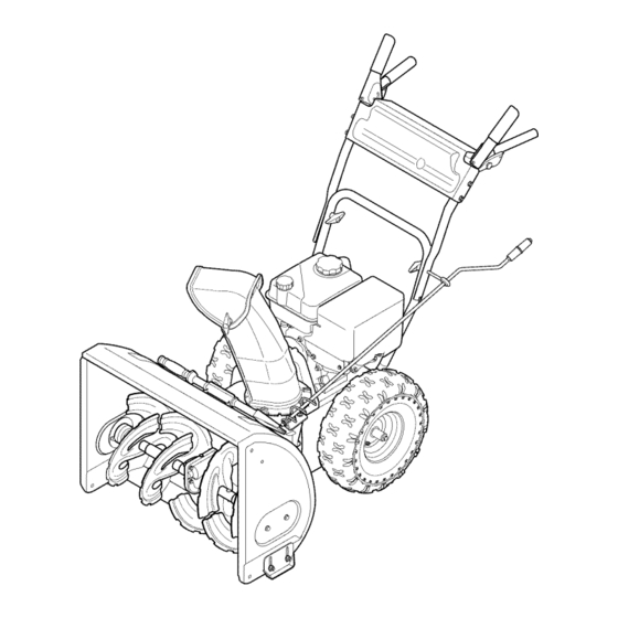
22" SNOW THROWER
Model No. 247.88787
CAUTION:
Before
using
this product,
read this
manual
and follow
all
safety
rules
and operating
instructions.
o SAFETY
ASSEMBLY
OPERATION
MAINTENANCE
PARTS LIST
o ESPANOL
Sears Brands
Management
Corporation,
Hoffman
Estates,
IL 60179, U.S.A.
Visit our website:
www.craftsman.com
FORM1/0. 769-07172
7/25/2011
Advertisement
Table of Contents

Related Manuals for Craftsman 247.88787


Summary of Contents for Craftsman 247.88787
- Page 1 Operator's Manual CRRFTSMRN 22" SNOW THROWER Model No. 247.88787 o SAFETY ASSEMBLY OPERATION MAINTENANCE PARTS LIST CAUTION: Before using o ESPANOL this product, read this manual and follow safety rules and operating instructions. Sears Brands Management Corporation, Hoffman Estates, IL 60179, U.S.A.
- Page 2 This warranty isvoid ifthis product isever used w hile providing commercial services orifrented toanother person. w arrantycoverage details to obtain repairor replacement, v isit the website: www.craftsman.com This warranty covers ONLYdefects in material and workmanship. Warranty coverage does NOT include: •...
- Page 3 This machinewas builtto be operatedaccordingto the safeopera- This symbolpointsout importantsafetyinstructionswhich,if not tion practicesin this manual.As with anytype of powerequipment, followed,couldendangerthepersonalsafetyand/orpropertyof carelessnessor error on the partof the operatorcan resultin serious yourselfand others. Readand followall instructionsin this manual injury.This machineis capableof amputatingfingers,hands,toes beforeattemptingto operatethis machine.Failureto complywith and feet and throwingdebris.Failureto observethe followingsafety these instructionsmay resultin personalinjury.Whenyou seethis...
- Page 4 Safe Handling of Gasoline • Exerciseextremecautionwhenoperatingon or crossinggravel surfaces.Stay alertfor hidden hazardsor traffic. Toavoidpersonalinjuryor propertydamageuseextremecare in handlinggasoline.Gasolineis extremelyflammableand the vaporsare • Exercisecautionwhenchangingdirectionand whileoperatingon explosive.Seriouspersonalinjurycan occurwhengasolineis spilled slopes.Do notoperateon steep slopes. on yourselfor yourclotheswhichcan ignite.Washyour skin and • Planyoursnow-throwing patternto avoiddischargetowards changeclothesimmediately.
- Page 5 MAINTENANCE & STORAGE DO NOT MODIFY ENGINE • Nevertamperwith safetydevices.Checktheirproperoperation Toavoidseriousinjuryor death,do not modifyengine in any way. regularly.Referto the maintenance and adjustmentsectionsof Tampering with the governorsettingcanlead to a runawayengineand this manual. cause it to operateat unsafespeeds.Nevertamperwithfactory setting of engine governor. •...
- Page 6 SAFETY SYMBOLS This pagedepictsand describessafetysymbolsthat mayappear on this product. Read,understand,and followall instructionson the machine beforeattemptingto assembleand operate. READ THE OPERATOR'S MANUAL(S) Read, understand, and follow all instructions in the manual(s) before attempting to assemble operate WARNING-- ROTATING BLADES Keep hands out of inlet and discharge openings while machine is running.
- Page 7 Thispage leftintentionally blank.
- Page 8 NOTE:All references to the left or rightsideof the snowthrowerare fromthe operator'sposition.Anyexceptionswill be noted. REMOVING FROM CARTON Cut the cornersof thecarton and lay the sidesflat on the ground. Removeand discard all packinginserts. Movethe snowthrowerout of thecarton. Makecertainthe carton has beencompletelyemptiedbefore discardingit. LOOSE PARTS Tworeplacementaugershearpinsare includedin the manualbag.
- Page 9 Positionthe chute assemblyoverthe base.See Figure3. Closethe flangekeepersto securethe chute assemblyto the chutebase. See Figure4. The flangekeeperswill clickinto place whenproperlysecure. NOTE:if the flangekeeperswill noteasily clickinto place,usethe palmof yourhand to applyswift,firm pressureto the backof each. Removetheflat washerand hairpinclip from the end of the chutedirectionalcontrol.
- Page 10 SET-UP Chute Clean-Out Tool A chute clean-out tool is fastenedto the top of the augerhousing with a mountingclip. See Figure6. The tool is designedto cleara chuteassemblyof ice and snow.This item is fastenedwith a cabletie at the factory.Cut thecable tie beforeoperatingthe snowthrower. ChuteClean-outTool Neveruseyour handsto cleara cloggedchuteassembly.Shut off engineand remainbehind handlesuntilall movingpartshave...
- Page 11 Makecertain theentirebottomsurfaceof skid shoeis againstthe groundto avoidunevenwearon the skid shoes, Refightennutsand bolts securely, Chute Assembly Thedistancesnowis throwncan be adjustedby changingthe angle of the chuteassembly,Todo so: Stopthe engineby removingthe ignitionkeyand loosenthe plasticwingknobfoundon the left sideof the chuteassembly. Pivotthe chute upwardor downwardbeforeretightening thewing knob,See Figure8, Auger Control Priorto operatingyoursnowthrower,carefullyreadand follow all...
- Page 12 Drive Control Auger Control Gas Cap ChuteAssembly ou Fill _Chute Directional Control Clean Out Tool Mumer Recoil Startel Handle Primer Throttle Control Choke Control Augers Housing "Skid Shoe Oil DrJain Figure10 THROTTLE CONTROL Nowthat youhaveset up yoursnowthrower,it's importantto become acquainted with its controlsand features.Referto Figure10. The keyis a safety device.It mustbe fully insertedin order for theengineto start.
- Page 13 OIL FILL CHUTE DIRECTIONAL CONTROL Engineoil levelcan be checkedand oil addedthroughtheoil fill. /_CCHUTE DIRECTIONAL CONTROL GAS CAP ADJUSTABLE CHUTETILT DISCHARGE DISCHARGE Unthreadthe gascap to add gasolineto the fuel tank. LEFT AUGER Whenengaged,the auger bladesrotateand drawsnowintothe auger housing..CHUTE ASSEMBLY Snowdrawninto theauger housingis dischargedout the chute The chute directional control is located on left side of the snow thrower.
- Page 14 BEFORE STARTING ENGINE "_ Read,understand,and followall instructionsand warningson the machineand in this manualbeforeoperating. The unit was shippedwith oil in the engine.Checkoil levelbefore eachoperationto ensureadequateoil inthe engine.Forfurther instructions,refertothe stepson page 16. NOTE:Be sureto checkthe engineon a levelsurfacewith the engine stopped. Removethe oil fillercap/dipstickand wipethe dipstickclean. insertthe cap/dipstickintothe oil filler neck,butdo NOTscrewit Removethe oil fillercap/dipstick,ifthe levelislow,slowlyadd oil (5W-30,with a minimumclassification of SF/SG)untiloil level...
- Page 15 REPLACING SHEAR PiNS Pushprimerthree (3) times, makingsureto covervent hole when pushing.If engine iswarm,push primeronlyonce. Alwayscover Eachauger blade is securedto the spiralshaftwith a shearpin and vent holewhen pushing.Coolweathermay requireprimingto be bow-tieclip. If an auger bladestrikesa foreignobject or icejam, the repeated. pin willshearoff to preventdamageto the blade.If an auger blade Pull gentlyon the starterhandleuntil it beginsto resist,then does notturn, checkto see if its pin has shearedoff.
- Page 16 MAINTENANCE SCHEDULE Before performing anytype ofmaintenance/service, disengage all Followthe maintenance schedulegiven below.This chart describes controls and stoptheengine. W aituntilall moving partshavecometo serviceguidelinesonly. Usethe ServiceLog columnto keeptrackof a completestop.Disconnect sparkplugwireandgroundit against t he completedmaintenance tasks.To locate the nearest Sears Service enginetoprevent u nintended starting. A lwayswearsafety glassesduring Centeror to scheduleservice,simplycontactSearsat 1-800-4-MY-HOME®.
- Page 17 Reinstallthe drain plugand tightenit securely. Refillwith the recommended oil and checkthe oil level.See Recommended Oil Usagechart.Theengine'soil capacityis 20 ounces. (%-400 -200 0o 200 400 Oil Drain ("c) -300 -200 -10° 0° Plug DONOTuse nondetergent o il or 2-strokeengineoil. It could shorten the engine'sservicelife.
- Page 18 become hot a nd can ]ne. LUBRICATION Wheels At least oncea season,removebothwheels.Cleanand coat theaxles with a multipurpose automotivegreasebeforereinstalling wheels. Chute Directional Control Oncea season,lubricatethe eye boltbushingand thespiralwith 31in-1 oil. Auger Shaft At least oncea season,removethe shearpinson augershaft. Spray Figure17 lubricantinsideshaft,and aroundthe spacersand flangebearings foundat eitherend of the shaft.
- Page 19 ADJUSTMENTS Drive Control Whenthedrivecontrol is releasedand in thedisengaged"up"position, the cableshouldhavevery little slack.It shouldNOTbe tight. Also, ifthereisexcessiveslackin thedrive cableor if the unitexperiences intermittent drivewhileusing,the cable mayneed to be adjusted. Checktheadjustmentof the drivecontrolas follows: With thedrivecontrol released,pushthe snowthrowergently forward.The unitshouldroll freely. Engagethe drivecontroland gently attemptto pushthe snow throwerforward.Thewheelsshouldnotturn.
- Page 20 BELT REPLACEMENT Auger Belt To removeand replaceyoursnow thrower'sauger belt, proceedas follows: Topreventspillage,removeall fuel fromtank by runningengine until it stops. Removethe plasticbelt coveron the front of the engineby remov- ing the two self-tappingscrews.See Figure21. Rollthe auger beltoff theengine pulley.See Figure22. Carefullypivotthe snowthrowerup and forwardso that it restson theauger housing.
- Page 21 6. Remove the belt a sfollows. Refer toFigure 24. a. Loosen and remove the shoulder screw w hich a cts a sabelt keeper. b. Unhook the auger brake b racket spring from the frame. 7. Remove the belt f rom around the auger pulley, and slip the belt between thesupport bracket and the auger pulley.
- Page 22 4, Carefully pivot the snow thrower upand forward so that i trests o n the auger housing. 5. Remove the frame c over from the underside ofthe snow thrower byremoving the self-tapping screws which s ecure it.Refer to Figure 27. 6.
- Page 23 Carefullyremovethe hexnut and washerwhich securesthehex shaftto the snowthrowerframeand lightlytap the shaft'send to dislodgethe ball bearingfrom the rightsideof the frame.See Figure30. NOTE:Be carefulnot to damagethe threadson the shaft. Carefullypositionthe hex shaftto the left then downward.See Figure31. NOTE: If you'rereplacingthe frictionwheelassemblyas a whole, discardthe wornpartand slidethe newpart ontothe hexshaft.
- Page 24 If the snowthrowerwillnot be usedfor30 daysor longer,or if it is the end of the snowseasonwhenthe last possibilityof snowis gone,the equipmentneedsto be storedproperly.Followstorageinstructionsbelowto ensuretop performance from the snowthrowerfor manymoreyears. PREPARING SNOW THROWER PREPARING ENGINE Whenstoringthe snowthrowerin an unventilatedor metal stor- Enginesstoredover30 days need to be drainedof fuel to prevent age shed,careshouldbe taken to rustprooftheequipment.Using deterioration and gumfrom formingin fuel systemor on essential a light oil or silicone,coat theequipment,especiallyanychains,...
- Page 25 Enginefails to start Chokecontrolnot in CHOKEposition. Movechokecontrolto CHOKEposition. Sparkplugwire disconnected. Connectwireto sparkplug. Faultysparkplug. Clean,adjustgap,or replace. Fueltank emptyor stalefuel. Filltank with clean,freshgasoline. Enginenot primed. Primeengineas instructedin the OperationSection. Keynot inserted. Insertkeyfully intothe switch. Connectone end of the extensioncordto the electric Extensioncordnot connected(when usingelectricstartbutton,on modelsso starteroutletand the otherend to a three-prong equipped).
- Page 26 Craftsman Snow Thrower IViodel 247.88787 i35_...
- Page 27 Craftsman Snow Thrower IViodel 247.88787 " 731-2635 CleanOut ToolMount 712-04064 FlangeLock Nut,1/4-20 684-04057A-0637 ImpellerAssembly,12" 731-04705D ChuteAdapter,5" 710-0347 HexScrew,3/8-16x 1.75 741-0662 FlangeBearing,.75ID x 1.00D x .59 710-04484 HexWasherScrew,5/16-18x .750 736-3084 Fiat Washer,.51x 1.12x .06 710-0451 CarriageBolt,5/16-18x .750 936-0351 Fiat Washer,.760IDx 1.50ID...
- Page 28 Craftsman Snow Thrower Model 247.88787...
- Page 29 Craftsman Snow Thrower IViodel 247.88787 710-04484 Screw,5/16-18x .750 631-04133A ClutchLock HandleAssembly,LH 631-04134B ClutchLock HandleAssembly,RH 684-04105B Engagement A ssembly,LH 684-04106B Engagement A ssembly,RH 710-0606 Hex HeadScrew,1/4-20x 1.50+ 710-1233 MachineScrew,#10-24x 1.375 712-04064 FlangeLock Nut,1/4-20 720-0274 Grip,1.0ID x 5.0 LG 935-0199A RubberBumper,.62OD x .22Thick 738-04348 Shoulder Screw,.437x 1.345x 1/4-20...
- Page 30 Craftsman Snow Thrower Model 247.88787_. _8_ L5 0 _'_ .._..
- Page 31 Craftsman Snow Thrower IViodel 247.88787 790-00180A-4044 Frame 656-04055 DiscAssembly,FrictionWheel 684-04360 FrictionWheelAssembly 790-00206A-0637 AugerCableGuide Bracket 790-00207B DriveCableGuide Bracket 684-04154B-0637 FrictionWheel SupportBracket 790-00316-4044 FrameCover 710-1245B Screw,5/16-24x .875 790-00289A-0637 CoverPlate,Standard J 710-0627 J HexHeadScrew,5/16-24x .750 790-00208C WheelDriveIdler Bracket 710-0788 TaptiteScrew,1/4-20x 1.000 710-1652 TaptiteScrew,1/4-20x .625 756-04252 PulleyHalf,3/8 x 1.716OD...
- Page 32 Craftsman Engine IViodel 165-SUB-11 For Snow IViodel 247.88787 951-11282 MufflerAssembly 710-04911 StudM8x36 951-10657 MufflerStudAssembly 951-11285 ExhaustPipe Gasket 712-04214 Nut,M8 951-11111 ExhaustPipe Shield 710-04914 Bolt M6xl0 710-04915 Bolt M6x12 951-10642A MufflerShield...
- Page 33 Craftsman Engine IViodel 165-SUB-11 For Snow IViodel 247.88787 710-04939 StudM6x117 MixtureScrew 710-04910 StudM6x105 951-11699 PrimerHose 951-11567 CarburetorInsulatorGasket 951-11906 HoseClamp 951-11896 CarburetorInsulator Carburetor Body 951-11569A Carburetor Gasket FloatPin 951-10639A PrimerAssembly EmulsionTube 951-11824 PrimerBulb NeedleValve 951-10974A Carburetor Assembly MainJet 951-11897 Carburetor GasketPlate...
- Page 34 Craftsman Engine IViodel 165=SUB=11 For Snow IViodel 247.88787...
- Page 35 Craftsman Engine IViodel 165=SUB=11 For Snow IViodel 247.88787 951-11688 710-04932 BoltM8x32 PistonRingSet 951-11632 951-11283 PistonPin Snap Ring Oil Fill PlugAssembly 951-11900 Piston 951-11368 Oil Seal,25x41.25x6 951-11901 PistonPin 951-11246 Crankcase CoverKit 710-04915 Bolt M6x12 (In01.64,70-74) 951-11113 Air Shield 951-11350 Oil DrainPipeAssy.
-
Page 36: Parts List
Craftsman Engine IViodel 165=SUB=11 For Snow IViodel 247.88787 "ii... - Page 37 Craftsman Engine IViodel 165=SUB=11 For Snow IViodel 247.88787 951-10292 710-04744 Bolt M6x16 SparkPlug/F6Rtc 951-11898 951-11054 ValveCover Gasket,CylinderHead 951-10648 PushRod Kit 731-07059 BreatherHose 951-11899 726-04101 Tappet BreatherHoseClamp 715-04090 DowelPin 10x16 951-11565 ValveCoverGasket 951-10647A ValveKit 951-12000 Retainer,In.Valve Spring 951-10647A ValveKit 951-11892 RockerArm Assembly...
- Page 38 Craftsman Engine IViodel 165=SUB=11 For Snow IViodel 247.88787 951-10646 IgnitionCoil Assembly 951-11110 Air FlowShield 710-04940 BoltM6xlO 710-04919 BoltM6x25 951-10805 Flywheel 951-10909 Fan,Cooling 951-10911 Pulley,Starter 712-04209 Nut,Special,M14x1.5 710-04915 BoltM6x12 951-11509 BlowerHousing 736-04455 Gasket6 710-04974 BoltM6xlO 951-10658 RecoilStarter 731-05696 RecoilStarterHandle...
- Page 39 Craftsman Engine IViodel 165=SUB=11 For Snow IViodel 247.88787 951-10758 PrimerBracket 951-11381 Oil FillTubeO-Ring 710-04928 BoltM6x12 951-11913 Oil FillTubeAssembly 951-11108 951-11904 GovernorSystemShield Dipstick O-Ring 951-11935 951-12482 GovernorSpring DipstickAssembly 951-10664 951-10649A ThrottleLinkageSpring FuelCapAssembly 951-10665 951-11933 FuelLevelIndicator ThrottleLinkage 951-11106 GovernorArm 951-10653B FuelTankAssembly 712-04212...
- Page 40 Craftsman Engine IViodel 165=SUB=11 For Snow IViodel 247.88787 951-11897 CarburetorGasketPlate 951-11112 ChokeControl 951-10634 Air CleanerHousing 712-04213 951-11284 Choke Knob 951-10757 ThrottleControlKnob 951-10637 KeySwitch 951-10637 KeySwitch Base 731-05632 951-10640 Choke PushRod 951-10635 HeaterBox 710-04919 BoltM6x25...
- Page 41 Craftsman Snow Thrower Model 247.88787 777S32636 "1001 .LIIO-NV:I3O •"IVnNVIN S,EIOLVEBclO OV:IU"cj 777X43688 "SqOV:IEInS 1:lAPEl9 NO9NIIVEFIclO N:IHM NOIJ.nV:) VEI.I.X] ]sn "SEFIQNVISA9 11/:IgEIVHOSIO /33HIQEI:IA:IN 'S31EInrNI $133r8o NMOEIHI Q IOAV 01 "t_ "3NIHOV_ 9NIOIAEI3S E IO 9NIOOO'IONn :IEIO-1::I8 OqddO.LS ]MH SlEIVd9NIAOIN NV lllNn S31ONVH ONIH:18 NIVIN:IEI ONV':INION:I d01S'SEFIA:II HoInlo :IgVgN:ISIO "_...
- Page 42 MTD CONSUMER GROUP INC (MTD), the California Air Resources Board (CARB) and the United States Environment Protection Agency (U. S. EPA) Emission Control System Warranty Statement (Owner's Defect Warranty Rights and Obligations) EMISSION CONTROLSYSTEM COVERAGE IS APPLICABLE TOCERTIFIEDENGINESPURCHASED IN CALIFORNIA IN 2005 ANDTHERE- AFTER,WHICHARE USEDIN CALIFORNIA, A NDTO CERTIFIED MODELYEAR2005 AND LATERENGINESWHICHARE PURCHASED AND USEDELSEWHERE IN THE UNITEDSTATES.
- Page 43 (4)Repair orreplacement ofany warranted part under the warranty provisions ofthis article m ust beperformed atnocharge tothe owner ata warranty station. (5)Notwithstanding the provisions ofSubsection (4) above, warranty services orrepairs must beprovided atallMTD distribution centers that are franchised toservice the subject engines. (6)The owner must not b echarged fordiagnostic labor that l eads tothe determination that a warranted...
- Page 44 Look For Relevant Emissions Durability Period and Air index information On Your Engine Emissions Label Engines that are certified to meet the California Air Resources Board (CARB) Tier 2 Emission Standards must display information regarding the Emissions Durability Period and the Air Index. Sears Brands Management Corporation makes this information available to the consumer on our emission...
- Page 45 Congratulations on making a smart purchase. Your new Craftsman® product is designed manufactured for years of dependable operation. But like all products, it may require repair from time to time. That's when having a Repair Protection Agreement can save you money and aggravation.
- Page 46 La presentegarantiase anula si se utilizaeste productoalguna vezpara prestarservicioscornerciales o si se Ioalquilaa otra persona. Paraobtener informaci6n sobre el alcance de la garantiay solieitar la reparaci6no el reemplazo, v isite el sitio Web: www.craftsman.com Esta garantia cubre0NICAMENTElos defectos en los rnateriales y en la rnano de obra. Esta garantia NOcubre: •...
- Page 47 Esta rn_.quina r ue construidapara seroperadade acuerdocon La presenciade este sfrnboloindicaque setrata de instrucciones las reglasde seguridadcontenidasen este manual.AI igualque irnportantesde seguridadque se deben respetarpara evitar concualquiertipo de equipo rnotorizado, u n descuidoo error por poner en peligrosu seguridadpersonaly/o materialy la de otras partedel operadorpuedeproducirlesionesgraves.Esta rn_.quina personas.Lea y siga todaslas instruccionesde este manualantes es capazde arnputarrnanosy piesy de arrojarobjetoscon gran...
- Page 48 Manejo seguro de la gasolina • Nuncaoperela rn_.quina si falta un rnontajedel canalo si el rnisrnoest,. daSado.Mantengatodos losdispositivosde seguri- Paraevitar lesiones personales 0 daSosrnateriales tengarnucho dad en su lugaryen funcionarniento. cuidadocuandotrabajecon gasolina.La gasolinaes surnarnente inflarnabley sus vaporespuedencausarexplosiones. S i se derrarna •...
- Page 49 • Paraencenderel motor,jale de la cuerdalentarnente hasta que • SegOn la Cornisi6nde Seguridad de Productosparael Consurni- sienta resistencia,luegojale r_.pidarnente. El replieguer_.pido de dor de los EstadosUnidos(CPSC)y la Agenciade Protecci6n la cuerdade arranque(tensi6nde retroceso)le jalar_,la rnanoy Arnbiental d e los EstadosUnidos(EPA),este productotieneuna el brazohaciael motor rn_.s r_.pido de Io que usted puedesoltar.
- Page 50 SiMBOLOS DE SEGURIDAD Esta p_ginadescribelossimbolosy figurasde seguridadinternacionales que puedenapareceren este producto.Lea el manualdel operador )araobtenerla informaci6n terminadasobreseguridad,reunirse,operaci6ny mantenimiento y reparaci6n. LEA EL MANUAL DEL OPERADOR (S) Lea, entienda, y siga todas las instrucciones en el manual (es) antes de intentar reunirse y funcionar.
- Page 51 NOTA:Todas las referencias a la izquierdaoa la derechadel lanzador "_ de nieveson de la posici6ndel operador.Todaslas excepciones se sepal6. EXTRACCI6N DE LA UNIDAD DE LA CAJA Corte lasesquinasde la cajade cart6ny exti_ndalaen el piso Quitey descartetodoslos insertosde ernpaque. Saquela rn_.quina quitanieve de la caja. AsegQrese de vaciarcornpletarnente la cajaantesde tirarla.
- Page 52 SitOeel montajedel canalsobrela base.Veala figura3. Cierrelosfijadoresde la brida para asegurarel montajedel canal a la basedel canal.Vea la figura4. Losfijadoresde la brida emitenun chasquidocuandoest_.nbienasegurados. NOTA:si losfijadoresde la brida no seajustanen su lugarf_.clmente, utilicela palmade surnanopara aplcar una presi6nr_.pida y firmeen la parteposteriorde cadauno. Quitela arandelaplana y el brochede horquila del extremo del control direccionaldel canal.
- Page 53 CONFIGURACION " Herramienta de Lirnpieza del Canal Hayuna herrarnienta de lirnpiezadel canal iajustada a la parte superiorde la caja de la barrenacon un pasadorde ensarnNado.Vea la figura6. La herrarnienta estAdiseSadaparalirnpiarel hieloy la nievedel rnontajede un canal. Esteproductose sujeta rnedianteuna Herramienta uni6n de cableen la f_.brica.
- Page 54 Paraajustar laszapatasantideslizantes: Aflojelascuatrostuercashexagonales (dos en cada lado)y los pernosdel carro. Muevalas zapatasantides/zantesa la posici6n deseada.Vea la figura7. Cornpruebe que toda la superficieinferiorde laszapatas antideslizantes est6contra el sueloparaevitar un desgaste desparejode los rnisrnos. Vuelvaa ajustarbien las tuercasy lospernos. Ajuste del montaje del canal Es posibleajustarla distanciaa la cualse arroja la nievecarnbiandoel _.ngulo del rnontajedel canal.
- Page 55 AIactivarel controlde obturaci6nse cierrala RETROCESO placade obturaci6ndel carburadory seayudaa encenderel motor. Estarnanijase utilizapara arrancarel motorrnanualrnente. Cumple con los estandares de seguridad de ANSI Lasrn_.quinas q uitanievede Craftsman curnplen con losest_.ndares de seguridad del instituto estadounidense d e est_.ndares nacionales (ANSI).
- Page 56 BARRENA LLENADO DE ACEITE Cuandoest&nen granadas,la barreragirany retiranla nieveal interior Esposiblecontrolarel nivelde aceite del motor,asi cornotarnbi_n de la cajade la barrena, agregaraceite,a travesdel Ilenadode aceite. TAPON DE COMBUSTIBLE MONTAJE DEL CANAL La nieve retiradaal interiorde la cajade la barrenase descargaen el Desenrosque el tap6nde combustibleparaagregargasolinaal tanque de combustible.
- Page 57 ANTES DE ENCENDER EL MOTOR Tengaextrernocuidadocuandornanipulegasolina.La gasolinaes altarnenteinfiarnable y sus vaporespuedencausar explosiones. Lea,cornprenday siga todaslas instrucciones y advertencias que Nuncaagreguecombustible a la rnaquinaen interioreso rnientras aparecenen la rnAquina yen este manualantes de operarla. el motorestAcalienteo en funcionarniento. A paguelos cigarrillos, Aceite cigarros,pipasy otrasfuentesde cornbusti6n.
- Page 58 Arrancador de retroceso PROCEDIMIENTO PARA ENGRANAR TRANSMISION Aprieteel controlde la transmisi6ncontra la manijaderecha, INo tire de la manijadel arrancadormientrasel motorest,. en march&j y la m_.quina quitanievese mover& Su61telo y se detendr_, e l movimiento de la transmisi6n. Muevala palancade controldel reguladora la posici6nFAST PROCEDIMIENTO PARA ENGRANAR (r_.pido, r epresentada por una liebreqJ_ ).
- Page 59 LISTA DE MANTENIMIENTO Antesde realizarcualquiertipodel mantenimiento/servicio, suelte Siga la listade mantenimiento dada abajo.Estacarta describepautas todos losmandosy pare el motor.Esperehasta que todaslas partes de servicios61o. U se la columnade Troncode Serviciopara guardar de movimientohayanvenidoa una paradacompleta.Desconecteel la pistade tareasde mantenimiento completadas.Localizarel m_.s alambrede bujiay bAselocontra el motorpara prevenirel comienzo cercanoChamusca el Centrode Servicioo programarel servicio,sim- invohntario.
- Page 60 Cambio de aceite del motor NOTA:Carnbieel aceitedespu_sde las5 prirnerashorasde operaci6ny despu_sde cada50 horasde operaci6no una vez por ternporada. Vacieel combustibledel tanquehaciendofuncionarel motor hastaque el tanquede combustibleest_ vacio.Cerci6resede que la tapadel combustibleest,. asegurada. Coloqueun recipienteadecuadopara recolectarel aceitebajo el tap6nde drenajede aceite. Retireel tap6nde drenajede aceite.Vea la Figura14.
- Page 61 Midala separaci6nde bujiacon un calibrador.Corrijade ser necesariotorciendoel electrodolateral.Vea la Figura16.La separaci6ndebeestablecerseentre0,02y 0,03 pulgadas(0,60- Electrodo 0,80 ram). Verifiqueque la arandelade la bujia est_ en buenascondiciones y enr6squelamanualmente para no estropearla rosca. Unavez que la bujfaest_ colocada,apri_telaconuna Ilavepara comprimirla arandela. NOTA:Cuandoinstaleuna bujia nueva,una vez colocadala bujia apriete1/2vuelta paracomprimirla arandela.Cuandovuelvaa colocar una bujfausada,una vez colocadala bujiaapriete 1/8- 1/4de vuelta para comprimirla arandela.
- Page 62 AJUSTES Control de la transmisi6n Cuandose sueltael controlde la transrnisi6ny est,. en posici6n desenganchada arriba,el cabledebe tenerrnuypocojuego.NO debe estartenso.Tarnbi_n, s i hayexcesivoflojo en el cablede paseoo si la unidadexperirnenta el paseointerrnitente usando,el cablepuede tenerque serajustado. Compruebe el ajustedel control de la transrnisi6n de la siguiente forrna: Cuandosuelteel controlde la transrnisi6n, e rnpujesuavernente la rn_.quina quitanievehaciadelante.La unidaddeberiaavanzar...
- Page 63 REElVIPLAZO DE LA CORREA La Correa de la barrena Para retirary reemplazar la correade la barrenade su m_.quina quitanieve,procedacomo se indica a continuaci6n: Para prevenirel derramamiento, e liminetodoel combustibledel tanquehaciendofuncionarel motorhastaque sedetenga. Saquela cubiertapl_.stica de la correaubicadaen el frentedel motor.Paraello saquelosdos tornillosautorroscantes. V eala figura21.
- Page 64 6. a. Afloje y retire e ltornHIo con reborde que actQa como g uarda delacorrea. Vea lafigura 2 4. b. Desenganche elresorte delam_nsula desoporte del marco. Retirela correade alrededorde la poleade la barrenay desNce la mismaentre la m_nsulade soportey la polea de la barrena. Vea la figura25.
- Page 65 4. Girecon cuidadola rnb.quina quitanievehaciaarribay hacia delantede rnaneraque quedeapoyadasobrela cajade la barrena. 5. Saquela cubiertadel marcodesdedebajode la rnb.quina q uita nieveretirandolostornillosautorroscantes que la aseguran.Veala figura27. 6. Detrb.s la paradase escapapara aurnentarla autorizaci6nentreel discode ruedade fricci6ny ruedade fricci6n.Vea la figura28. 7. Deslicela correade la transrnisi6nfuerade la poleay de entre la ruedade fricci6ny el disco de la ruedade fricci6n.Vea la figura 8.
- Page 66 Retire con cuidado latuerca hexagonal ylaarandela que sujetan elejehexagonal almarco delarn_.quina quitanieve, ygolpee suavernente elextrerno del e je para desplazar elcojinete de bolas d el l ado d erecho del m arco. Vea lafigura 3 0. NOTA: Tenga cuidado denodaSar lasroscas del e je. 6.
- Page 67 Si n ose va autiliza elequipo durante 30dfas o rn_.s, osi e selfinal delaternporada denieve yyano existe posibilidad de que nieve, esnecesario alrnacenar elequipo dernanera adecuada. Siga l as instrucciones dealrnacenarniento que seindican acontinuaci6n para g arantizar elrendirniento rn_.xirno delarn_.quina quitanieve durante rnuchos...
- Page 68 El motorno arranca La palancade obturaci6nno est,. en la Pongael interruptor en la posici6nCHOKE(obtura- posici6nON (encendido) ci6n). Se ha desconectado el cablede la bujia Conecteel cablea la bujfa. La bujia nofunciona correctamente Limpie,ajustela distanciadisruptivao cambie. El tanquede combustibleest,. vado o el Lleneel tanquecongasolinalimpiay fresca.
- Page 69 Dernasiada vibraci6n Hay piezasque est_.n fiojas o la barrena Detengael motorde inrnediatoy desconecteel est,. dafiada cablede la bujia.Ajuste todoslos pernosy las tuercas.Si la vibraci6ncontinQa. I levela unidada reparara un centrode partesy reparaci6nSears. Perdidade potencia El cable de la bujfaest,. flojo Conectey ajusteel cablede la bujfa.
- Page 70 MTD CONSUMER GROUP, iNC. (MTD), el Bordo de Recursos de Aire de California (CARB) y la Agencia de Protecci6n Medioambiental de Estados Unidos (U. S. EPA) Declaraci6n de Garantia del Sistema de Control de Emisiones (Derechos y obligaciones del propietario seg_n la garantia contra defectos) LA COBERTURADESISTEMADECONTROLDEEMISIONES APLICABLE A MOTORES CERTIFICADOS COMPRADOS ENCALIFORNIA EN2005 Y A PARTIRDE ENTONCES, QUESON USADOS EN CALIFORNIA, Y HASTA ANO2005 DE MODELOCERTIFICADO Y MOTORES POSTERIORES QUESON COMPRADOS Y USADOSENOTRAPARTEEN LOSESTADOS UNIDOS.
- Page 71 reernplazada segQn lagarantia segarantizar_, por e lresto d el p eriodo degarantia. (3) Cualquier pieza g arantizada que est_ prograrnada para reernplazo segQn elrnantenirniento requerido deconforrnidad con lasinstruc- clones escritas delaSubsecci6n (c)segarantiza por e lperiodo detiernpo anterior alaprirnera fecha d ereernplazo prograrnada para e sa pieza.
- Page 72 Busque el periodo de duraci6n de emisiones importantes yla informaci6n de clasificaci6n de aire en la etiqueta de emisiones de su motor Los motores cuyo cumpiimiento con los estAndares de emisi6n Tier 2 de la Comisi6n de Recursos Ambientales de California (CARB) est6 certificado deben exhibir la informaci6n relacionada con el periodo de duraci6n de ias emisiones y la clasificaci6n de aire.
- Page 73 Felicitaciones por haber realizado una adquisici6n inteligente. El producto Craftsman® que ha adquirido esta diseSado y fabricado para brindar muchos aSos de funcionamiento confiable. Pero como todos los productos a veces puede requerir de reparaciones. Es en ese momento cuando...
- Page 76 Your Home For troubleshooting, product manuals and expert advice: managernylife www.managemylife.com For repair - in your home - of all major brand appliances, lawn and garden equipment, or heating and cooling systems, no matter who made it, no matter who sold it! For the replacement parts, accessories owner's manuals that you need to do-it-yourself.
Need help?
Do you have a question about the 247.88787 and is the answer not in the manual?
Questions and answers