Advertisement
Quick Links
WARNING!
READ AND UNDERSTAND
OPERATOR'S MANUAL
BEFORE USING THIS UNIT.
FAILURE TO FOLLOW
OPERATING INSTRUCTIONS
COULD RESULT IN INJURY
OR DAMAGE TO PROPERTY.
Manufactured & Distributed By:
Model #
A Division of Russell Corporation
Toll-Free Customer Service Number for U.S.: 1-800-558-5234
http://www.huffysports.com
1
10/11/04
P/N 21463403
© COPYRIGHT 2004 by HUFFY SPORTS
Advertisement

Related Manuals for Huffy MGC6430


Summary of Contents for Huffy MGC6430
- Page 1 FAILURE TO FOLLOW OPERATING INSTRUCTIONS COULD RESULT IN INJURY OR DAMAGE TO PROPERTY. Manufactured & Distributed By: Model # A Division of Russell Corporation Toll-Free Customer Service Number for U.S.: 1-800-558-5234 http://www.huffysports.com 10/11/04 P/N 21463403 © COPYRIGHT 2004 by HUFFY SPORTS...
-
Page 2: Safety Instructions
NOTICE TO ASSEMBLERS ALL Huffy Sports basketball Systems, including those used for DISPLAYS, MUST be assembled and ballasted with sand or water according to instructions. Failure to follow instructions could result in SERIOUS INJURY. It is NOT acceptable to devise a makeshift weight system. - Page 3 PARTS LIST ItemQty.Part No. Description 206646 Tank (Black) 200628 Wheel Axle 226401 Wheel 900060 Top Pole Section 908057 Middle Pole Section with Label 900254 Bottom Pole Section Assembly 203041 Nut, Hex Flange, 3/8-16 201342 Wheel Bracket 201651 Spacer, Wheel Axle 201568 T-Strap 206219...
- Page 4 WARNING FAILURE TO FOLLOW THESE WARNINGS MAY RESULT IN SERIOUS INJURY AND/OR PROPERTY DAMAGE. Owner must ensure that all players know and follow these rules for safe operation of the system. • DO NOT HANG on the rim or any part of the system including backboard, support braces or net.
- Page 5 PARTS IDENTIFIER- Hardware is actual size 22. Washer, .406 I.D. x 1.0 O.D -Qty (3) 13. Bolt, Carriage, 3/8-16 x 1.5 Long-Qty (1) 7. Nut, Hex Flange, 3/8-16-Qty (1) 16. Bolt, Carriage, 5/16-18 x 1.75 Long-Qty (3) 23. Bolt, Carriage, 5/16-18 x 4 Long-Qty (2) 10.
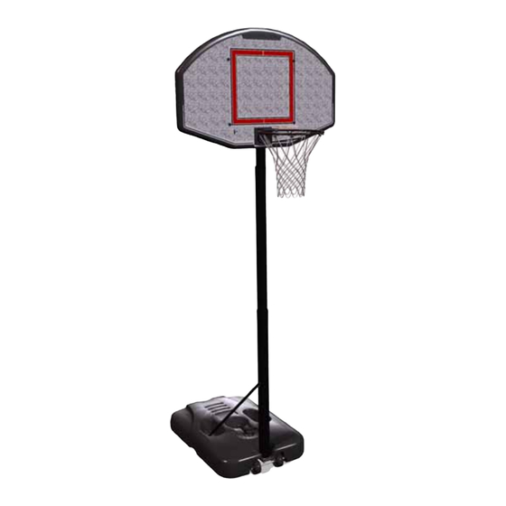
- Page 6 Get to know the basic parts of your basketball system..FRONT BACK BACKBOARD ELEVATOR ASSEMBLY TOP POLE MIDDLE POLE STRUTS BOTTOM POLE BASE WHEEL CARRIAGE ASSEMBLY Toll-Free Customer Service Number for U.S. : 1-800-558-5234 P/N 21463403 10/11/04 http://www.huffysports.com...
- Page 7 Correctly identify each pole section. Poles have an identification sticker that will be used as a reference point in the next step. Reference Stickers MIDDLE BOTTOM Toll-Free Customer Service Number for U.S. : 1-800-558-5234 10/11/04 P/N 21463403 http://www.huffysports.com...
- Page 8 IMPORTANT! ONCE POLE SECTIONS ARE POUNDED TOGETHER- THEY CANNOT BE TAKEN APART Align poles using alignment marks. First, pound top and middle poles together by bouncing them on a scrap piece of alignment mark wood on the ground as shown in FIG B. until they no longer move toward pole identification stickers.
- Page 9 Install wheel axle (2) through wheel bracket (9) and install wheels (3) onto wheel axle (2) with spacers (10) as shown. IMPORTANT!: THE SPACER (10) WILL FIT LOOSELY UNTIL SECURED INTO THE CAVITY OF THE BASE. Attach wheel carriage assembly to base (1) with bolt (13), washer (22), and nut (7) as shown.
- Page 10 Attach pole assembly to tank assembly as shown. Secure pole assembly to tank and wheel bracket by turning the pole assembly clockwise as shown. Tighten pole completely and further rotate pole until struts are aligned correctly as shown in FIG B. WARNING! TWO PEOPLE REQUIRED FOR THIS PROCEDURE.
- Page 11 Rotate struts down and bend struts outward to line up with holes on base as shown. Secure free ends of tank struts to tank with carriage bolt (16), washer (22), and knob (17) as shown. Repeat for other side. WARNING! KNOBS MUST BE TIGHTENED COMPLETELY AND CHECKED PERIODICALLY...
- Page 12 Pole bracket will need to be lightly pressed into backboard ribbing. Be sure to press completely into place. Attach rim to backboard and pole bracket (20) with knob (17), reinforcement bracket (24), and carriage bolt (16) as shown. Tighten knob completely. NOTE: WARNING! BOARD STYLE...
- Page 13 Attach board assembly to pole with carriage bolts (23) and knobs (17) as shown. Install pole cap (12) as shown. Place assembled unit in desired location. Fill tank with water (26 gallons/98.4 liters) or sand (approx. 360 lb./163 kg) and snap tank cap (14) in place. Insert T-strap (11) through slot on back of base as shown.
- Page 14 Attach net clips to rim as shown. WARNING! CLIP “ARM” USE OF THIS PRODUCT WITHOUT PROPER INSTALLATION OF SMART CLIPS ® , OR WHEN ALL SMART CLIPS ® ARE NOT PRESENT COULD RESULT IN BODILY HARM. BE SURE TO FOLLOW DIRECTIONS CAREFULLY.
-
Page 15: Side View
Install net. SIDE VIEW NETCLIP Insert net into bottom of clip as shown. SIDE VIEW Twist net until it snaps into position. Net must be centered through clip. NETCLIP Toll-Free Customer Service Number for U.S. : 1-800-558-5234 10/11/04 P/N 21463403 http://www.huffysports.com... - Page 16 Attach height and moving label (15) to front of pole as shown. Regulation rim height is 10 feet. CAUTION! HEIGHT ADJUSTMENT Rest unit on support table. Remove adjustment knobs (A) and carriage bolts (B) to extend or retract backboard and rim. Height adjustment from 7 ’...
- Page 17 FRANÇAIS DEUTSCH ESPAÑOL Aucun outil Aucun outil requis requis Assemblage Assemblage Assemblage facile facile facile Economie de Economie de temps de 40 % temps de 40 % Keine Werkzeuge Keine Werkzeuge erforderlich erforderlich Einfacher Einfacher Einfacher Zusammenbau Zusammenbau Zusammenbau 40% weniger 40% weniger Zeitaufwand Zeitaufwand...
- Page 18 AVIS AUX PERSONNES CHARGÉES DU MONTAGE TOUS les systèmes de basket-ball Huffy Sports, y compris ceux utilisés en EXPOSITION, DOIVENT être assemblés et lestés de sable ou d'eau, selon les instructions. Suivez ces instructions sous peine d'encourir des BLESSURES GRAVES. Il est INACCEPTABLE de composer un système de lestage de fortune.
-
Page 19: Consignes De Sécurité
Klimatische Bedingungen, Korrosion oder Fehlgebrauch kann zu Systemdefekten führen. Technische Unterstützung kann direkt von Huffy Sports angefordert werden. Die Mindestspielhöhe beträgt 1,98m (6,6 Fuß) bis zur Unterkante der Korbwand. Die meisten Verletzungen werden durch einen Fehlgebrauch bzw. ein Missachten der Anleitungen verursacht. - Page 20 LISTE DES PIÈCES TEILELISTE LISTA DE PIEZAS LégendeQuantité No de réf. Description Anz. Teilenummer Beschreibung 206646 Réservoir (noir) 206646 Tank (Schwarz) 200628 Axe des roues 200628 Radachse 226401 Roue 226401 900060 Section de poteau supérieure 900060 Oberes Stangenteil 908057 Section de poteau centrale avec étiquette 908057 Mittleres Stangenteil mit Aufkleber 900254...
- Page 21 Toll-Free Customer Service Number for U.S. : 1-800-558-5234 10/11/04 P/N 21463403 http://www.huffysports.com...
- Page 22 DESCRIPTIF DES PIÈCES - La visserie est grandeur nature. TEILESCHLÜSSEL - Die Befestigungsteile sind in ihrer tatsächlichen Größe abgebildet. IDENTIFICADOR DE PIEZAS: El herraje aparece en su tamaño real IDENTIFICATION DES PIÈCES - Pas à la grandeur réelle TEILESCHLÜSSEL - Die einzelnen Teile sind nicht in ihrer tatsächlichen Größe abgebildet. IDENTIFICADOR DE PIEZAS: Las piezas no aparecen en su tamaño real Apprenez à...
- Page 23 • Identifiez correctement chaque section de poteau. Les poteaux ont une étiquette d'identification qui servira de point de repère à l'étape suivante. • Jedes Stangenteil richtig identifizieren. Die Stangenteile sind mit Aufklebern markiert, die als Orientierungshilfe für den nächsten Schritt dienen. •...
- Page 24 IMPORTANT! UNE FOIS LES SECTIONS DE POTEAU ENTRECHOQUÉES ENSEMBLE, ELLES NE PEUVENT PLUS ÊTRE DÉMONTÉES. WICHTIG! NACH DEM ZUSAMMENSTAUCHEN DER STANGENTEILE KÖNNEN DIESE NICHT MEHR VONEINANDER GETRENNT WERDEN. ¡IMPORTANTE! UNA VEZ QUE LAS SECCIONES DEL POSTE SE HAN EMBRAGADO ENTRE SÍ, YA NO SE PODRÁN SEPARAR •...
- Page 25 IMPORTANT! • Enfilez l'axe des roues (2) dans le chariot à roues (9) et installez les roues (3) ¡IMPORTANTE! WICHTIG! sur l'axe (2) avec les entretoises (10), comme illustré. • Die Radachse (2) wie gezeigt durch das Radlaufwerk (9) schieben und die Räder (3) mit Abstandsstücken (10) auf die Radachse (2) schieben.
- Page 26 Attachez l'ensemble du poteau au réservoir, comme illustré. Fixez le poteau sur le réservoir et le support des roues en tournant le poteau dans le sens des aiguilles d'une montre, comme illustré. Serrez le poteau à fond et tournez-le encore jusqu'à ce que les contrefiches soient correctement alignées, comme illustré à la figure B.
- Page 27 • Tournez les contrefiches vers le bas et courbez les contrefiches vers l'extérieur pour les aligner sur les trous du socle, comme illustré. Fixez les extrémités libres des contrefiches sur le réservoir avec le boulon ordinaire (16), la rondelle (22) et le bouton (17), comme illustré. Faites de même de l'autre côté. •...
- Page 28 Vous devrez appuyer légèrement sur le support de poteau pour l'insérer dans les crans du panneau. Veillez à l'enfoncer complètement en position. Attachez le cerceau au panneau et le support de poteau (20) avec le bouton (17), le support de renforcement (24) et le boulon ordinaire (16), comme illustré. Serrez le bouton à fond.
- Page 29 Attachez le panneau au poteau avec les boulons ordinaires (23) et les boutons (17), comme illustré. Placez le capuchon (12) sur le poteau, comme illustré. Den Korbwandaufbau wie gezeigt mit den Schlossschrauben (23) und Drehknöpfen (17) an der Stange befestigen. Die Stangenkappe (12) wie gezeigt aufsetzen.
- Page 30 Attachez les pinces de filet au cerceau, comme illustré. AVERTISSEMENT ! Die Netzhalteklammern wie gezeigt am Korbrand anbringen. WARNUNG! ¡ADVERTENCIA! Instale los sujetadores de la red en el borde, como se muestra. L'UTILISATION DE CE PRODUIT SANS L'INSTALLATION CORRECTE DES SMART CLIPS®...
- Page 31 Installez le filet. Das Netz anbringen Instale la red. VUE DE CÔTÉ SEITENANSICHT VISTA LATERAL PINCE DE FILET NETZHALTEKLAMMER SUJETADOR DE LA RED FILET NETZ Insérez le filet dans la base de la pince, comme illustré. Das Netz wie gezeigt unten in den Clip stecken. Introduzca la red en la parte inferior del sujetador como se muestra.
- Page 32 Collez l'étiquette de hauteur et de déplacement (15) sur l'avant du poteau, comme illustré. La hauteur réglementaire du cerceau est de 3,05 m (10 pieds). Den Höhen- und Transportaufkleber (15) wie gezeigt an der Vorderseite der Stange anbringen. Der Korbrand wird den offiziellen Regeln gemäß in einer Höhe von 3,05 m (10 Fuß) angebracht.
Need help?
Do you have a question about the MGC6430 and is the answer not in the manual?
Questions and answers