Intermec 6400 User Manual
Hide thumbs
Also See for 6400:
- Programmer's reference manual (234 pages) ,
- User manual (205 pages) ,
- Tutorial (114 pages)

Related Manuals for Intermec 6400


Summary of Contents for Intermec 6400
- Page 1 6400 Hand-Held Computer USER’S GUIDE " " " " " " " " " " " " " " " " " " " " " " " " " " " " PN: 961-047-093 Revision E December 2001...
- Page 2 " NOTICE The information contained herein is proprietary and is provided solely for the purpose of allowing customers to operate and service Intermec manufactured equipment and is not to be released, reproduced, or used for any other purpose without written permission of Intermec.
-
Page 3: Table Of Contents
Main Battery Pack ....... 1-21 6400 Hand-Held Computer User’s Guide... - Page 4 ......... . . 2-15 6400 Hand-Held Computer User’s Guide...
- Page 5 ......2-21 Setting Up Your Intermec 1551 Series RS-232 Serial Scanner Parameters ......
- Page 6 ........4-11 APPENDIX A Connector Pin-Outs 8-Pin Docking Connector (standard) ....6400 Hand-Held Computer User’s Guide...
- Page 7 ........4-11 6400 Hand-Held Computer User’s Guide...
- Page 8 ......3-51 Table 4-1 Basic Troubleshooting ..... . . 6400 Hand-Held Computer User’s Guide...
-
Page 9: General Information
Steps you through some procedures to use when trouble- shooting. This section also includes information for routine maintenance. Routine maintenance includes recharging the main battery pack; replacing the handstrap; and cleaning various components. Appendix A Pin-outs for the external connectors. 6400 Hand-Held Computer User’s Guide... -
Page 10: Unpacking And Inspecting
Follow their instructions for filing a claim on the damaged items. Authorized repair of products is available only at Intermec Service Centers. Unauthorized repair voids any and all warranties. 6400 Hand-Held Computer User’s Guide... -
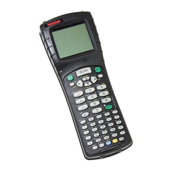
Page 11: Hand-Held Computer Main Components
SECTION 1 General Information Hand-Held Computer Main Components Display Buzzer Keyboard Figure 1-1 Computer Front View 6400 Hand-Held Computer User’s Guide... -
Page 12: Figure 1-2 Computer Back View
General Information SECTION 1 Product Label Battery Pack Latch Battery Pack Figure 1-2 Computer Back View 6400 Hand-Held Computer User’s Guide... -
Page 13: Figure 1-3 Top End View
SECTION 1 General Information Radio Card Slot Scanner (option) Figure 1-3 Top End View IrDA Interface Docking Connector and Communication Adapter Connector Figure 1-4 Bottom End View 6400 Hand-Held Computer User’s Guide... -
Page 14: Hand-Held Computer Keyboard
Numeric Keys Backspace Key Green Shift Key Function Keys (F1- -F12) Specially Defined Function Space Key Keys (depending on keyboard overlay used) I/O (Suspend/Resume) Key Blue Shift Key Yellow Shift Key Figure 1-5 41- Key Keyboard 6400 Hand-Held Computer User’s Guide... -
Page 15: 51-Key Keyboard
Window Scrolling Keys Numeric Keys Backspace Key Shift Key Alphabetic Keys Special Defined Function Keys (depending on keyboard over- lay used) I/O (Suspend/Resume) Key Blue Shift Key Yellow Shift Key Figure 1-6 51- Key Keyboard 6400 Hand-Held Computer User’s Guide... -
Page 16: Key Descriptions
Use the period [.] key as a period or a decimal point. Minus [- ] Key Use the minus [--] key to enter negative values or dashes in character fields. The minus key is also used for “No” re- sponses to display prompts. 6400 Hand-Held Computer User’s Guide... -
Page 17: Numeric Keys
Your keyboard may have up to three color-coded legends (words or charac- ters) above some of the keys. The green, blue, or yellow “shift” keys correspond to those options. 6400 Hand-Held Computer User’s Guide... - Page 18 Yellow Key Use the yellow shift key to enter single keystroke entries of that shifted option. The yellow shift functions relates to the yellow legends on your keyboard. 1-10 6400 Hand-Held Computer User’s Guide...
-
Page 19: Using Shifted Functions
On a PC these key strokes produce a 4, 6, and 8. Numeric values 0--9 are available on all the 6400 Hand- Held Computer versions, those keys are used for special controls without causing compatibility issues. - Page 20 LOCK is engaged then pressing shift and a key usually pro- duces something other than what you want. Therefore, just like with a PC, to get the result you want you have to change a mode or the sequence you press the keys. 1-12 6400 Hand-Held Computer User’s Guide...
-
Page 21: Display Annunciator Locations On Display Window
Position 1 is located in the lower left hand corner and position 20 com- pletes the row in the lower right hand corner. Figure 1-7 Annunciator Locations On Display 6400 Hand-Held Computer User’s Guide 1-13... -
Page 22: Annunciator Descriptions
Shift mode: After holding down the green Shift [SHFT] key, the next character will be uppercase or the alternative function. Control mode: Generally you use the Control mode as it is designed in by your particular application. 1-14 6400 Hand-Held Computer User’s Guide... - Page 23 [1] key produces an ‘A’. Using the Alphabetic Lock: Pressing the [1] key produces an ‘A’; pressing the blue shift key and then the [1] key produces the charac- ter ‘1’. 6400 Hand-Held Computer User’s Guide 1-15...
- Page 24 " NOTE: If you have the beeper turned off, you will not hear any of the low battery beep warnings. 1-16 6400 Hand-Held Computer User’s Guide...
-
Page 25: Display Contrast
This allows you to pan across the entire virtual CGA screen. 6400 Hand-Held Computer User’s Guide 1-17... -
Page 26: [L/O] Suspend Or Resume
Available as options and accessories are an adjustable handstrap and an adjustable wriststrap. These are shown in NO TAG and NO TAG on pages 1-29 and NO TAG and can be attached for either left or right handed use. 1-18 6400 Hand-Held Computer User’s Guide... -
Page 27: Figure 1-8 Bottom End Handstrap Attachment
SECTION 1 General Information Handstrap Attachment Hole Handstrap Attaching Hole Handstrap Screw Figure 1-8 Bottom End Handstrap Attachment Handstrap Clip Fastner Handstrap Attachment Bushings Figure 1-9 Top End Handstrap Attachment 6400 Hand-Held Computer User’s Guide 1-19... -
Page 28: Buzzer
2 cell pack and 3 hours for a 4 cell pack. You should charge the battery pack until the green LED on the charger comes on, indicating a fully charged pack. 1-20 6400 Hand-Held Computer User’s Guide... -
Page 29: Battery
Level on page 2-7 for instructions. Battery Main Battery Pack There are this options for rechargeable lithium ion main battery packs: Two cell " Four cell " Four cell in optional scanner handle " 6400 Hand-Held Computer User’s Guide 1-21... - Page 30 Your computer will not accept data or process transactions until you deal with the low battery condition. The backup battery protects the data that you have entered for at least 100 hours. 1-22 6400 Hand-Held Computer User’s Guide...
-
Page 31: Backup Battery
5 years before it needs to be replaced. If your computer fails to hold data for at least 100 hours in the suspend mode, send your computer to the Intermec Customer Support Center for replacement. Memory... -
Page 32: Flash
They can provide useful information to an Intermec Cus- tomer Support Specialist, should your computer fail to oper- ate. You will be instructed by Intermec service personnel to complete the necessary steps while they are troubleshooting your system with you. -
Page 33: Batch Terminal Operation
902 MHz or 2.4 GHz spread spectrum radio. This computer with a radio provides for both batch (store and forward data transfer later) and real-time (right now) inter- action with your host computer or network for flexibility of operation. 6400 Hand-Held Computer User’s Guide 1-25... -
Page 34: Communication Adapter
Communication Adapter Scanner Connector Charge Jack The Communication Adapter contains a charge jack on the side for connecting and charging your hand-held computer using an optional AC wall charger or DC cigarette charger accessory. 1-26 6400 Hand-Held Computer User’s Guide... -
Page 35: Scanner Handle
Lightweight " Easy to connect and use " Optional four cell battery pack " Can easily detach so the batteries can be charged sep- " arately from the hand-held computer. 6400 Hand-Held Computer User’s Guide 1-27... -
Page 36: Figure 1-12 Scanner Handle
General Information SECTION 1 Scanning Trigger Two Cell Battery Pack in Hand- Held Computer Figure 1-12 Scanner Handle 1-28 6400 Hand-Held Computer User’s Guide... -
Page 37: Adjustable Handstrap And Adjustable Wriststrap
You can order an optional adjustable handstrap (Figure 1-13) or wrist strap (Figure 1-14). Top Handstrap Clip Fastener Computer Attachment Screw Hole Handstrap Adjustment Buckle Handstrap Attachment Screw Hole Bottom Handstrap Attachment Screw Figure 1-13 Adjustable Handstrap 6400 Hand-Held Computer User’s Guide 1-29... - Page 38 General Information SECTION 1 Wrist loop Computer Wrist Strap Attachment Screw Hole Adjustable Knob (push button in, slide knob down strap) Wrist Strap Attachment Screw Wrist Strap Attachment Screw Hole Figure 1-14 Adjustable Wrist Strap 1-30 6400 Hand-Held Computer User’s Guide...
-
Page 39: Hand-Held Computer Specifications
Fast charge (fully charge ¶ 1.5 hours for a 2 cell (32 to 104 F) pack and 3 hours for a 4 cell pack) Communication: Physical Asynchronous RS-232 and RS-485, IrDA, Wireless devices: Local Area Network 6400 Hand-Held Computer User’s Guide 1-31... - Page 40 Radio Module: 2.4 GHz 802.11 Direct Sequence Spread Spectrum Interface: Internal Range: Up to 800 feet (244 meters) Data Rates 1 or 2 Mbps, auto selecting (throughput): Modulation: 802.11 Direct Sequence Spread Spectrum (FHSS) 1-32 6400 Hand-Held Computer User’s Guide...
- Page 41 Up to 1200 feet (366 meters) line of sight Data Rates 90,225,450 kbps, programmable (throughput): Modulation: Direct Sequence Spread Spectrum (DSSS) Frequency 902--928 MHz, 915--928 MHz (Australia) Band: Output Power 250 mW Regulatory FCC 15.247; Industry Canada RSS 210 Compliance 6400 Hand-Held Computer User’s Guide 1-33...
-
Page 42: Configuring Terminal Emulation Over Ip
For TE/IP, the host is usually specified by an IP address (unless you are using a domain name server). This can cause a problem because often the 6400 computer needs to know which port the host application is residing on. The default port number (23) is automatically assumed in TE/ IP. -
Page 43: 6400 Hand-Held Computer User's Guide I
" Charge the battery pack " Download applications and parameters " Program the Flash memory " “Power-up” your hand-held computer " Understand the key clicks " Scan using integrated (internal) or tethered (external) " scanners 6400 Hand-Held Computer User’s Guide... -
Page 44: Before Using Your Hand-Held Computer For The First Time
1. Insert a fully charged main battery into your comput- 2. Perform the four finger reset (both Enter keys, blue shift, and yellow shift keys) simultaneously. See Figure 2-1 (page 2-3) for location of keys. 6400 Hand-Held Computer User’s Guide... -
Page 45: Figure 2-1 Resetting Your Computer
3. Allow your computer to “boot” up and leave it sus- pended for 10 hours. " NOTE: Suspend means to press and hold the I/O key until the display goes blank. 4. Insert a new and fully charged battery pack to begin operations. 6400 Hand-Held Computer User’s Guide... -
Page 46: Rechargeable Battery Labelling
The lithium battery can explode if placed incorrectly in the charger. AVERTISSEMENT: Les batteries au lithium peuvent exploser ou prendre feu si elles sont trop chargées à cause d’une mauvaise installation de la station d’accueil. 6400 Hand-Held Computer User’s Guide... -
Page 47: Installing The Main Battery
(see Figure 2-2). 2. Press in on the battery pack until it snaps into place. Release Latch Rechargeable Battery Pack (contacts on underside) Battery Compartment Figure 2-2 Installing Main Battery Pack 6400 Hand-Held Computer User’s Guide... -
Page 48: Removing The Main Battery
1. With your thumb, firmly push the release latch for- ward. Battery pops up and out of the compartment. 2. Lift battery out. Release Latch Rechargeable Battery Pack (contacts on underside) Figure 2-3 Removing Main Battery Pack 6400 Hand-Held Computer User’s Guide... -
Page 49: Measuring Battery Pack Charge Level
LED = 21- -25% charge level; two LEDs = 26- -50% charge level; three LEDs = 51- -75% charge level; four LEDs = 76- -100% charge level Figure 2-4 Main Battery Pack Capacity Contacts 6400 Hand-Held Computer User’s Guide... -
Page 50: Charging Your Battery Pack
6400 Series vehicle dock " The multidock, single dock, and vehicle dock installation and instructions are contained in a separate publication 6400 Series Docks Installation Instructions NPN: 962-020-004. Using the optional Communication Adapter allows you ac- cess to charging your computer by using: An ac wall charger "... -
Page 51: In An External Source
Fuse Holder Battery Pack Compartments (eight) Power Cord Connector Charge Indicator LED Figure 2-5 Multipack Charger Battery Pack Compartment Power Cord Charger Contacts Charging Indicator LED Figure 2-6 Single Pack Charger 6400 Hand-Held Computer User’s Guide... -
Page 52: Battery Charger Led And Error Codes
No Communication Orange Red Checksum Error Upper Cell Mismatch 1 and 3 Orange Off Lower Cell Mismatch 1 and 3 Orange Orange Off 5 Bad Packets Re- ceived Orange Red Orange Off Wrong Battery Type 2-10 6400 Hand-Held Computer User’s Guide... -
Page 53: Backup Battery
The backup battery is not user-replaceable. To have your backup battery replaced, send it in to the Intermec Customer Service Center nearest to you. Whenever you send in your computer for service, include a description of what you would like to have done to it. -
Page 54: Downloading Programs To Your Hand-Held Computer
The upper 256 KB of flash is reserved for the BIOS and DOS files. If this area ever needs updating you will be furnished with complete instructions along with the updated files. 2-12 6400 Hand-Held Computer User’s Guide... -
Page 55: Turning Your Hand-Held Computer On And Off
The memory contents are protected when the power is suspended. Terminal Emulation programs do not automatically sus- pend. When lying idle but not manually suspended, the in- tegrated radio module is still active and will drain battery 6400 Hand-Held Computer User’s Guide 2-13... -
Page 56: Understanding The Key Clicks
If you enter an incorrect action or keystroke, you hear a “beep.” An error “beep” is longer than a key click. An error “beep” is intended to get your attention and let you know an error occurred. 2-14 6400 Hand-Held Computer User’s Guide... -
Page 57: Scanning
Complete details for setting up the parameters and oper- ating the integrated scanner are contained in the PEN*KEY Model 6400 Programmer ’s Reference Guide NPN: 977-054-004. 6400 Hand-Held Computer User’s Guide 2-15... - Page 58 SCAN key within 1/2 second, to get the laser beam back on. With the laser beam on, you have five seconds to find and scan the next bar code. RIGHT WRONG 012345 012345 2-16 6400 Hand-Held Computer User’s Guide...
-
Page 59: Installing The Optional Scanning Handle
To attach the handle: 1. Slip the handle onto the base of your hand-held com- puter. 2. Secure the two quarter-turn screws. Bottom of Computer Scanner Handle Quarter-turn Screw Fasteners Figure 2-7 Optional Scanner Handle 6400 Hand-Held Computer User’s Guide 2-17... -
Page 60: Using A Tethered Bar Code Scanner
858-065-072 PSC5300 IP Series Ultra Long Range part number " 858-065-092 PSC5300 IP Series Long Range High Power part " number 858-065-152 PSC5300 IP Series Extra Long Range High Power " part number 858-065-172 2-18 6400 Hand-Held Computer User’s Guide... -
Page 61: Software
The software that supports tethered scanning is V1.15+ BIOS and V5.10+ terminal emulations. Tethered scanning is supported for any external device that sends its serial data at 9600 baud, 8 data bits, no parity, 1 6400 Hand-Held Computer User’s Guide 2-19... -
Page 62: Setting Terminal Emulation To Accept Tethered Laser Scanners
If you experience problems with using your laser scanner with terminal emulation try these steps: 1. Reboot to the DOS prompt ([YELLOW] [BLUE] [ENT] [ENT]) press 0 at pause. 2. Type DEL CONFIG.DAT press [ENT]. 3. Press [CTRL] [ALT] [DEL] to reboot. 2-20 6400 Hand-Held Computer User’s Guide... -
Page 63: Setting Your Dos Application To Accept Tethered Laser Scanners
Options) to enable your laser scanner to work with the 64SCN7B scanner driver on your computer. Set All Defaults Scan the Set All Defaults bar code to set up your scanner for RS-232 serial communication. 6400 Hand-Held Computer User’s Guide 2-21... - Page 64 CANCEL. PREFIX 4. Scan the SUFFIX bar code. 5. Scan the SUFFIX values 1,0,0,3 bar codes from page 2-23. If you make a change or wish to change your selection, scan CANCEL. SUFFIX 2-22 6400 Hand-Held Computer User’s Guide...
- Page 65 SECTION 2 Operation RS-232 Host Prefix/Suffix Values CANCEL 6400 Hand-Held Computer User’s Guide 2-23...
- Page 66 Operation SECTION 2 RS-232 Host Parity NONE RS-232 Host Stop Bit Select 1 STOP BIT RS-232 Host ASCII Format 8-BIT 2-24 6400 Hand-Held Computer User’s Guide...
- Page 67 If your computer application beeps when it gets scanner data then you would probably want to disable the laser beep. DO NOT BEEP AFTER GOOD DECODE BEEP AFTER GOOD DECODE 6400 Hand-Held Computer User’s Guide 2-25...
-
Page 68: Setting Up Your Intermec 1551 Series Rs-232 Serial
Setting Up Your Intermec 1551 Series RS-232 Serial Scanner Parameters To allow the Intermec 1551 Series Tethered Scanners to in- terface with your computer you need to follow these steps: Scan the bar codes in the following order: 1. Reset to Factory Defaults 2. - Page 69 SECTION 2 Operation 4. Number 9 5. Number 9 6. Number 0 7. Number 2 8. Save Prefix 6400 Hand-Held Computer User’s Guide 2-27...
- Page 70 Operation SECTION 2 9. No Parity 10. Enable Code Id Character 11. Set Suffix 12. Number 9 13. Number 9 2-28 6400 Hand-Held Computer User’s Guide...
- Page 71 1. Refer to the user guide for your scanner. 2. Refer to the PEN*KEY Model 6400 Programmer ’s Reference Guide NPN: 977-054-004 3. Call your Intermec Technologies Corportation techni- cal support center 1--800--755--5505 (USA or Canada) or 1--425--356--1799 (elsewhere). 6400 Hand-Held Computer User’s Guide...
- Page 72 Operation SECTION 2 2-30 6400 Hand-Held Computer User’s Guide...
-
Page 73: Terminal Emulation Menu Screens
The Terminal Emulation Menu Screens are provided to sup- port terminals running Intermec Terminal Emulation or 6400 TCP/IP software. This section describes the menus used to set operating and scanning parameters for the hand-held computer. Additional information can be found in the programmer ’s guide or technical overview for your par-... -
Page 74: Enter [Ent] Keys
(example: 0--32). You may have to press [ENT] after these. These instances are detailed in the text that applies to those menus, or in the menu displays. 6400 Hand-Held Computer User’s Guide... -
Page 75: Y Up And B Down Arrows
1 shows the active session number 1 or Sending. Radio is sending data to the base station. Receiving. Radio is receiving data from the base station. This annunciator appears only when the information is for this particular computer’s address. 6400 Hand-Held Computer User’s Guide... -
Page 76: Display Position 2
Display Position 4 Alpha Lock. This Alpha Lock symbol is used only for the 41-key keyboard model. 6400 Hand-Held Computer User’s Guide... -
Page 77: Display Positions
The battery pack icons on your computer display reflect the same status as the LEDs on the battery pack. However, there may be a one minute delay for updating the icons on the display when the battery pack is replaced. 6400 Hand-Held Computer User’s Guide... -
Page 78: Setting The Operating Parameters
Blue shift, for functions labeled by blue legends above " the keys. Green shift, for functions labeled by green legends " above the keys. Yellow shift, for functions labeled by yellow legends " above the keys. 6400 Hand-Held Computer User’s Guide... - Page 79 After the Main Menu appears, enter a number (1 through 7) to make a selection. The Main Menu is shown below: Main Menu 1) Set-up Parms 2) LCD Parms 3) Beeper Setup 4) Tests 5) Version Info 6) Exit Menus 7) More 6400 Hand-Held Computer User’s Guide...
- Page 80 (mac address) To return to the Main Menu from the computer menus pro- gram, simply press the [ENT] key several times. You can then select 6) Exit Menus, to return to the operating sys- tem. 6400 Hand-Held Computer User’s Guide...
-
Page 81: Lcd Parms
Key click (indicating that a valid key has been pressed " or a good scan occurred) Error tone (indicating some error condition occurred; " for example, an unacceptable keystroke.) 6400 Hand-Held Computer User’s Guide... -
Page 82: Exit Menus
“initial” screen. If you changed any parameters the following screens will appear: Save Parms Enter ’Y’ to save parms If you enter ’y’ or ’Y’ this screen will appear: Save Parms Enter Password password is > ..cr52401 3-10 6400 Hand-Held Computer User’s Guide... -
Page 83: Opening The Set-Up Parms Menu
1. Press the [1] key. 2. Press the [ENT] key. 3. At the prompt, enter the password CR52401. The Set-Up Parms menu, and the menus you can access from it, are shown on the following page. 6400 Hand-Held Computer User’s Guide 3-11... - Page 84 6) VT220 7) Native Protocol Display Opts Firmware name 1) Backlight 1) SST 2) Cursor Mode 2) SST-Diag Mode Cold Start Set-up Parms 1) Menu Password 2) Print Device Enter “Y” To Cold Start terminal: 3-12 6400 Hand-Held Computer User’s Guide...
- Page 85 NET.CFG file you get this message. LAN ID changed Need to reboot to take effect. If this happens the system modifies your net.cfg file which is used by the WTPPKT.EXE program on initialization of your computer. 6400 Hand-Held Computer User’s Guide 3-13...
- Page 86 ENTER Set Mode/Channel Set Mode/Channel Use Cursor Up Use Cursor Up and Down Keys and Down Keys To Adjust To Adjust DS xxxx channel xx xxxxxxxxx ENTER (continue to Host/Cntl setups) 3-14 6400 Hand-Held Computer User’s Guide...
- Page 87 # xxx Host Name Enter up to 16 char- acters/Numbers for a name. ENTER Emulation (X) Enter Unit 1) Native 2) 3270 3) 5250 4) VT/ANSI ENTER Telenet (x) 1) Enabled 2) Disabled ENTER 6400 Hand-Held Computer User’s Guide 3-15...
- Page 88 (3270, 5250, or VT/ANSI). Tell the hand-held computer the name of each host. " " NOTE: Selections in these menus apply only to the current session. Use the Session Menu to verify or change the current session. 3-16 6400 Hand-Held Computer User’s Guide...
- Page 89 ENTER Set Mode/Channel Set Mode/Channel Use Cursor Up Use Cursor Up and Down Keys and Down Keys To Adjust To Adjust DS xxxx channel xx xxxxxxxxx ENTER (continue to Host/Cntl setups) 6400 Hand-Held Computer User’s Guide 3-17...
- Page 90 " NOTE: Selected options are highlighted on the display. To deselect a se- lected option, press the key that corresponds to that option. 3-18 6400 Hand-Held Computer User’s Guide...
- Page 91 10 formula and is used infre- quently. For additional information on Mod10, refer to the book PEN*KEY 6400 Programmers Reference Guide p/n: 977-054-004. Concatenate: Each bar code read is added to the end of the previous bar code read until the computer meets a condition that forces transmission to the host.
- Page 92 (such as minimum and maximum length, fixed lengths, leading and trailing character options, etc.). Once the length requirements have been set, the computer returns to the same Scan Options menu. You may then 3-20 6400 Hand-Held Computer User’s Guide...
- Page 93 6) Expand E To A Code 39 Code 128 1) Enabled 1) Enabled 2) Chk Digit 2) UCC/EAN 3) Extended 3) No UCC Type 4) Encoded 4) UCC F1 Value 5) Auto-Encoded 7) Full ASCII Codabar 1) Codabar 6400 Hand-Held Computer User’s Guide 3-21...
- Page 94 When you have enabled all needed bar code symbologies, press the [ENT] key. You return to the first Scan Options menu. Press the [ENT] key again to back out and return to the Set-Up Parms menu. 3-22 6400 Hand-Held Computer User’s Guide...
- Page 95 The Lengths Options menus determine the maximum and minimum length for a specific bar code symbology. Setting the length of enabled bar codes helps the hand-held com- puter determine if a scanned bar code is valid and improves response time. 6400 Hand-Held Computer User’s Guide 3-23...
- Page 96 (bar code type) (bar code type) Drop Leading Max Length Min Length Fix Length 1 (bar code type) (bar code type) Drop Leading Max Length Drop Trailing Min Length Fix Length 1 Fix Length 2 3-24 6400 Hand-Held Computer User’s Guide...
- Page 97 After you have set all of the length options for the enabled bar code the display returns to one of the Scan Options me- nus (depending on which menu you enabled the bar code from). 6400 Hand-Held Computer User’s Guide 3-25...
-
Page 98: Protocol Options
2000 characters instead of 1920. The default setting for 6400 WTP using Native Terminal Emulation is 120 columns by 16 rows (equals 1920). The default for VT220 Terminal Emulation is 80 columns by 24 rows (equals 1920). - Page 99 With this option ENABLED, the host computer can change or use the following features of the hand-held computer: RS-232 communications (e.g., printer) " Bar code options " Display screen and font size " Error tone " 6400 Hand-Held Computer User’s Guide 3-27...
- Page 100 RESET key on the hand-held computer itself. The Auto Tab Scan option causes the cursor to automatical- ly tab forward to the next input field when a good scan is obtained. 3-28 6400 Hand-Held Computer User’s Guide...
- Page 101 1. Press [1] to enable the Beep On Error option. Press [2] to enable the Auto Tab Scan option. Press [3] to enable the Telnet option, this can not be changed if you are using 6400 TCP/IP. 2. Press [ENT] to return to the Protocol Options menu screen.
- Page 102 Telnet allows for the handling of telnet option negotiations to establish a session with an appropriate telnet server. This can not be changed if you are using 6400 TCP/IP. Origin Set when enabled, will reset the screen origin when an exclamation mark is found in the data stream.
- Page 103 Enabling Auto Entr Scn actuates the [ENT] function when- ever a good scan is obtained. The Auto Tab Scan option causes the hand-held computer to automatically tab to the next input field when a good scan is obtained. 6400 Hand-Held Computer User’s Guide 3-31...
- Page 104 You can get a command from the host that defines the Function keys. If UserKey Locked is set the host ignores this command while this option is set. 3-32 6400 Hand-Held Computer User’s Guide...
- Page 105 Select your choice, then press the [ENT] key to return to the Protocol Opts menu. VT220 Mode 1) Char 2) Block Selecting Lock Mode disables the Mode key in the VT220 data stream. The default Mode key toggles between block and character modes. 6400 Hand-Held Computer User’s Guide 3-33...
- Page 106 1) Telnet allows for the handling of telnet option negoti- ations to establish a session with an appropriate telnet server. This can not be changed if you are using 6400 TCP/ Make your selection, then press the [ENT] key to return to the Protocol Opts menu.
- Page 107 6) Terminal Mode, the control codes are sent back to the host as either 7 or 8 bit. Native (For 6400 WTP Only) This option is enabled by default to preserve backward com- patibility. When enabled, pressing <F1> is equivalent to pressing Blue-0, while pressing <F2>...
-
Page 108: Display Options
And Down Keys To Adjust Use the up[Y] and down[B] arrows to select a number from Off to 255. This is the number of seconds that the backlight stays on after a key is pressed. 3-36 6400 Hand-Held Computer User’s Guide... -
Page 109: Radio Comm
This menu allows you to enable or disable SST diagnostic mode. " NOTE: Diagnostic modes disable data compression and are reserved for engineering tests. Protocol 1) SST 2) SST-Diag Mode For Proxim 3) Security ID terminals only 6400 Hand-Held Computer User’s Guide 3-37... - Page 110 You need to enter a 16 character security ID and repeat a second time. Then the following screen appears: Protocol Security ID changed. Save parms then re- boot terminal for change to take af- fect. 3-38 6400 Hand-Held Computer User’s Guide...
-
Page 111: Cold Start
The default is to have this option disabled. Set-UP Parms 1) Menu Password 2) Print Device Enable Password 1. Press the [1] key. 6400 Hand-Held Computer User’s Guide 3-39... -
Page 112: Print Device
2) IRDA Print 1. Press [1] for the RS232. 2. Press [2] for the IRDA. LCD Parms The LCD Parms (parameters) menu allows you to adjust the following features of the liquid crystal display: 3-40 6400 Hand-Held Computer User’s Guide... -
Page 113: Screen Size
It is also possible to have selected 5, 8, 10, and 16 for num- ber of rows. This depends on what size of display you have selected. Only one option can be selected at a time. 6400 Hand-Held Computer User’s Guide 3-41... -
Page 114: Screen Mode
(data) on the hand-held com- puter display. In order to see all of the data on the screen, use the arrow keys to scroll (or “move”) the view port of the screen on the display. 3-42 6400 Hand-Held Computer User’s Guide... - Page 115 The Page Mode option divides the full CRT screen into predefined “pages,” and starts the hand-held computer dis- play on page 1. The cursor first appears in the upper-right corner of the display. As you scroll, only the cursor moves 6400 Hand-Held Computer User’s Guide 3-43...
-
Page 116: Annunciators
You can also select Stealth Mode which displays the annun- ciators only when you make a change and then hides it when you press a key. 3-44 6400 Hand-Held Computer User’s Guide... -
Page 117: Key Uppercase
Option 2 causes the cursor to move by the virtual screen size selected in LCD Parms under the Main Menu. Options 3 and 4 manually define the x-axis and y-axis (up and down) movement of the cursor when option 1 (tab size) is selected. 6400 Hand-Held Computer User’s Guide 3-45... -
Page 118: Beeper Setup
Click menu screen and subscreens are shown below. Key Click 2) Length 3) Frequency Length Frequency Use Cursor Up Use Cursor Up And Down Keys And Down Keys To Adjust To Adjust Key Click> Key Click> 3-46 6400 Hand-Held Computer User’s Guide... -
Page 119: Error Tone
Beeper Setup 1) Beep Internal To turn the beeper select option Off: 1. Press [1] key to turn off the internal beeper. 2. Press [ENT] to confirm your selection and return to the previous screen. 6400 Hand-Held Computer User’s Guide 3-47... -
Page 120: Tests
Keyboard, which tests the operation of the hand-held " computer keyboard. Scanner, which tests the operation of a bar code scan- " ner attached to the hand-held computer. The peripherals menu is shown below. Detailed descriptions of each peripheral test follow. 3-48 6400 Hand-Held Computer User’s Guide... -
Page 121: Table 3-1 Possible Rf Link Descriptions
RFLink, is a general description of the overall quality " of RF connection between the Lucent radio in the 6400 (station) and the radio in the AP. The Lucent radio grades the RF link on a scale between 0 and 92. This value represents the RF channel Signal-to-Noise Ra- tio. - Page 122 Service Set ID (SSID), is a 32 character, alphanumeric " string that identifies the service set, or infrastructure, with which the 6400 is currently associated. The SSID is a user configurable parameter. The SSID is config- ured by the keyword WaveLAN_Network_Name in the net.cfg file.
-
Page 123: Table 3-2 Supported Transmission Rates For The High Speed Lucent Radio's
Table 3-2 Supported Transmission Rates for the High Speed Lucent Radio’s Value Description Fixed Low (1 Mb/s) Fixed Standard (2 Mb/s) ARS High (11 Mb/s = default) 6400 Hand-Held Computer User’s Guide 3-51... - Page 124 The TX output to the RX input " The DTR output to the DSR input " The CTS output to the RTS input " The RS232 Test screens are shown below. 3-52 6400 Hand-Held Computer User’s Guide...
-
Page 125: Display Test
Display Test The Display Test activates each element in the LCD dis- play. If a line appears broken, or there are gaps in the dis- play, the LCD panel needs to be replaced. 6400 Hand-Held Computer User’s Guide 3-53... - Page 126 3. Visually inspect the lines using the same criteria. The display screen is then painted black. 4. Visually inspect the painted black lines. For the test to pass, the screen should be uniformly black; press [ENT]. You return to the Peripherals menu. 3-54 6400 Hand-Held Computer User’s Guide...
-
Page 127: Keyboard Test
For this test to pass the bar code and the bar code length should appear on the display. Press any key to exit. The Scanner Test screen is shown below. Scanner Test Scan Code> Length> 6400 Hand-Held Computer User’s Guide 3-55... -
Page 128: Memory View
F4 - Memory Dump Address: xxxxxx Packet Driver Test The Packet Driver tests allow you to test the accuracy of data transmissions to and from the hand-held computer. Packet Driver 3) Packet Stats 4) Histogram 3-56 6400 Hand-Held Computer User’s Guide... - Page 129 The Packet Stats (statistics) test shows the number of pack- ets sent and received, number of errors, and number of packets dropped. Receive Statistics Lost Transmit Statistics Tranaction Statistics Qty/Min RTC Statistics * See Text ’Histogram Options’ 6400 Hand-Held Computer User’s Guide 3-57...
-
Page 130: Histogram Opts
Terminal Emulation Menu Screens SECTION 3 Histogram Opts An Intermec engineer may ask you to access this menu if your hand-held computer has problems. From this menu you can provide the Intermec system engineer with vital information about your hand-held computer. -
Page 131: Numbers
The version of the program you are using " The release date of the program " Version of radio driver " Mac address of computer. " Version Info Firmware Name Version x.xx Date ddmmmyy MLID Name xx.xx xxxxxxxxxxxx 6400 Hand-Held Computer User’s Guide 3-59... -
Page 132: Exit Menus
Use the Keyboard Opts (options) menu to choose the Type- Ahead option. This lets you key in information when the hand-held computer cannot immediately send data to the host computer. Keyboard Opts 1) Type-Ahead 3-60 6400 Hand-Held Computer User’s Guide... -
Page 133: Save Parms
(or intended) session must be identified (or desig- nated) before setting Parameters. When you select Set Hot Key, the current hot key is dis- played. Use the up and down keys to view the available 6400 Hand-Held Computer User’s Guide 3-61... - Page 134 And Down Keys And Down Keys To Adjust To Adjust Session: < xx > Host: xxxx <Datastream>..xxx Copy Setup Copy Setup is password Protected “Copy Setup” copies parameters of back- ground session to the current session. 3-62 6400 Hand-Held Computer User’s Guide...
-
Page 135: To Exit Emulation Mode And Return To Dos
C:\ prompt. If you do the hard reset of pressing and holding the blue and yellow shift keys, and both [ENT] keys this exits you to the beginning of the current emulation you are using. 6400 Hand-Held Computer User’s Guide 3-63... - Page 136 Terminal Emulation Menu Screens SECTION 3 3-64 6400 Hand-Held Computer User’s Guide...
-
Page 137: Maintenance And Troubleshooting
These battery icons represent the charge level in your main battery pack. Four icons indicates more than 76 % charge level " Three icons indicates between 51--75% " Two icons indicates between 26--50% " One icon indicates between 21--25% " 6400 Hand-Held Computer User’s Guide... - Page 138 Pack” instructions beginning on page 2-8 and the “Back- up Battery” instructions on page 2-11. If it does not re- spond when inserted into the equipment that provides charge, another problem could exist. If this happens, refer to the Troubleshooting section for solutions. 6400 Hand-Held Computer User’s Guide...
-
Page 139: Cleaning Your Hand-Held Computer
Never pour cleaners directly on the display nor the case. Instead put the cleanser on a soft cloth and gently wipe the case. Case and Display Intermec Corporation recommends cleaning the exterior of your computer using a soft cloth dampened with: MICRO-CLEAN II cleanser, made by Foresight In- "... -
Page 140: Troubleshooting
Therefore, a fully charged battery pack after 500 cycles And Fewer LEDs shows less than four lit LEDs, this is normal. Plan your Are Lighting charging needs accordingly, and note that the capacity continues to decrease with each cycle. 6400 Hand-Held Computer User’s Guide... - Page 141 For the complete details concerning Computer Into A the sequence of the colors of the blinks refer to Section 2 Charging Device Battery Charger LED and Error Codes on page 2-10. The Charge LED Blinks Different Colors 6400 Hand-Held Computer User’s Guide...
- Page 142 This is OK if connected to a charger or placed in a dock. If this is not the case, and either of these conditions continues for a long period of time, contact Intermec support personnel, as this condition runs down the batteries.
- Page 143 Ensure that the tethered laser is configured for 9600, n, 8, 1 Data Does Not and the bar code data is prefixed with an STX (0x02) and Show Up In The suffixed with an ETX (0x03). Key Buffer But The Integrated Laser Data Does 6400 Hand-Held Computer User’s Guide...
- Page 144 Do not leave both lengths set, if only one is needed, because Interleaved 2 of 5 can easily mis-decode into an incorrect length. 6400 Hand-Held Computer User’s Guide...
- Page 145 If these basic solutions do not solve your problem, there could be a number of possible causes. Additional things to try: Refer to the software documentation written for your " application. This documentation may contain trouble- shooting information. 6400 Hand-Held Computer User’s Guide...
-
Page 146: Diagnostic Information
1--800--755--5505. Diagnostic Information Your computer is equipped with diagnostics. You might be asked to perform tasks to help the Intermec Customer Sup- port Specialist or the Customer Response Hot Line Special- ist diagnose the problems that you are having. -
Page 147: Repair Service
If possible pack all products in their original boxes. If the original containers are not available, carefully pack each piece and provide plenty of packing material. This helps prevent additional damage to your product while in transit. 6400 Hand-Held Computer User’s Guide 4-11... - Page 148 Maintenance and Troubleshooting SECTION 4 4-12 6400 Hand-Held Computer User’s Guide...
-
Page 149: Appendix A Connector Pin-Outs
Computer Bottom End View (Without Optional Communication Endcap) Signal Function BCLK Battery Clock 12.0 Volts Charge Power Ground BDAT Battery Data Transmit Data Receive Data Request To Send Clear To Send Figure A-1 8-Pin Docking Connector Pinouts 6400 Hand-Held Computer User’s Guide... -
Page 150: Optional Communication Adapter 9-Pin D-Sub Connector
Request To Send Clear To Send 5 volts * Figure A-2 9-Pin D-Sub Connector Pinouts B CAUTION: * 5 volts on pin 9 is for use with tethered scanners and printers only, this may damage modems. 6400 Hand-Held Computer User’s Guide... -
Page 151: Entry Point
“NORAND UTILITIES”, and the specific screen name, such as MODEM PARAME- TERS. Key Description: (dark bar at the bottom) contains " “action” keys. Movement keys, such as arrows, are not shown. 6400 Hand-Held Computer User’s Guide... -
Page 152: Pop-Up Menus
Press the number of a suboption, or press the Y or B keys to scroll through the list and press the [ENT] key to enter. Select one suboption each time. Press the [- -] key to exit a drop-down list. 6400 Hand-Held Computer User’s Guide... -
Page 153: Alphanumeric Fields
If your computer has an alphanumeric keyboard, press the characters, then press the [ENT] key to move to the next field. Press [ENT] to save the entries and exit the menu. Press the [- -] key to exit without saving the entries. 6400 Hand-Held Computer User’s Guide... -
Page 154: Title Screen
Utilities Program APPENDIX B Title Screen When you reboot or reset your computer, the Title Screen appears: NORAND UTILITIES 64 UTILS V01.05 COPYRIGHT NORAND CORP. 1994--1997 ALL RIGHTS RESERVED [ENT]CONTINUE Press the [ENT] key to continue. 6400 Hand-Held Computer User’s Guide... -
Page 155: Language Selection
[- -]QUIT Press the number of a language, or press the Y or B keys to scroll through the list, then press the [ENT] key to enter. Press the [- -] key to exit this menu. 6400 Hand-Held Computer User’s Guide... -
Page 156: Communications Menu
If your computer does not support any of the features listed, the following pop-up menu appears. Press the [ENT] key to continue: COMMUNICATIONS FEATURE NOT SUPPORTED [ENT]CONTINUE The Communications Menu appears after the Title Screen: 6400 Hand-Held Computer User’s Guide... -
Page 157: Option 1 Begin Comm Session
If you select this option and Option 2. COMM SETTINGS is set to NETWORK, this Communication Status menu ap- pears: NORAND UTILITIES COMMUNICATIONS COMM SETTINGS: NRINET SERVER NAME CLIENT IP ADDRESS 0.0.0.0 0.0.0.0 SIGNING ON STATUS: [- -]STOP COMM 6400 Hand-Held Computer User’s Guide... - Page 158 If the session is unsuccessful, LAST SESSION appears with the failure status, such as “T803.” NORAND UTILITIES COMMUNICATIONS COMM SETTINGS: NRINET SERVER NAME CLIENT IP ADDRESS 0.0.0.0 0.0.0.0 SIGNING ON STATUS: LAST SESSION T803 INVALID HOST NAME OR IP ADDRESS [- -]STOP COMM 6400 Hand-Held Computer User’s Guide...
- Page 159 If you select this option and Option 2. COMM SETTINGS is set to ACCESSORY CARD, the system attempts to exe- cute the application from a PC card. If the “MISSING SYS- TEM FILES” message appears, press the [ENT] key to con- tinue. 6400 Hand-Held Computer User’s Guide...
- Page 160 COMM SETTINGS. There are five sta- tuses possible: “G” Good session " “T” Unexpected end of transmission " “H” Incorrect file header encountered " “F” File error encountered " “L” Telecommunications aborted before first file " header received B-10 6400 Hand-Held Computer User’s Guide...
- Page 161 Name deleted “124” Session ended abnormally “125” Name conflict “126” Incompatible remote device “133” Network interface is busy “134” Too many commands outstanding “135” Invalid LAN adapter number “136” Command completed while cancel occurring 6400 Hand-Held Computer User’s Guide B-11...
- Page 162 “88” Invalid response format “89” No significant response from modem “97” COM port disabled by system due to low battery or removal of PC card modem. “98” Unrecognized English response “99” Memory allocation error B-12 6400 Hand-Held Computer User’s Guide...
- Page 163 “806” Block sent was incomplete or block received was incomplete. “807” Client and server negotiation failed. “808” Server specified an unsupported block size. “809” Invalid buffer pointer. “810” All server connections are already in use. Try again later. 6400 Hand-Held Computer User’s Guide B-13...
- Page 164 User aborted communications by pressing [- -] key. “201” TFTP.EXE failed. “202” TFTP.EXE not found. “203” Unknown server. “204” Remote file name is invalid. “205” Local file name is invalid. “206” File not found on server. “207” Timeout. B-14 6400 Hand-Held Computer User’s Guide...
-
Page 165: Option 2 Comm Setting
Option 2. COMM SET- TING. See a sample menu on page B-6. Press the [- -] key to exit this drop-down list. The computer takes you to the Communications Menu. 6400 Hand-Held Computer User’s Guide B-15... - Page 166 Option 2. COMM SETTING: NORAND UTILITIES COMMUNICATIONS 1. BEGIN COMM SESSION 2. COMM SETTING MODEM/DIRECT 3. UNIT ID 4. MODEM PARAMETERS MODEM TYPE NM2400/NM2400A PROTOCOLBPS FMT 2400 8N1 AUTO ANSWER 5. PHONE NUMBER 9...131369282 6. ADVANCED UTILITIES B-16 6400 Hand-Held Computer User’s Guide...
- Page 167 Communications Menu with ACCESSORY CARD or INTERSERVER assigned to Option 2. COMM SETTING. NORAND UTILITIES COMMUNICATIONS 1. BEGIN COMM SESSION 2. COMM SETTING ACCESSORY CARD 3. UNIT ID 6. ADVANCED UTILITIES Suboption 4 HANDHELD 6400 Hand-Held Computer User’s Guide B-17...
-
Page 168: Option 3 Unit Id
[F4] key to reset the ID to factory default. Press [- -] to exit this pop-up menu. Option 4 NETWORK PARAMETERS Network Parameters appears as Option 4 when Option 2. COMM SETTINGS is set to one of these three NETWORK options: NRINET, TFTP, or NOVELL NETWARE. B-18 6400 Hand-Held Computer User’s Guide... - Page 169 Press the Y or B keys to move between fields. Press [ENT] to save the entries and exit the Network Pa- rameters menu. Press the [- -] key to exit without saving the entries. 6400 Hand-Held Computer User’s Guide B-19...
-
Page 170: Option 4 Modem Parameters
4. DATA FORMAT 5. AUTO ANSWER [- -]DONE Press the number of a modem parameters option, or press the Y or B keys to scroll through the list, then press the [ENT] button to enter. B-20 6400 Hand-Held Computer User’s Guide... - Page 171 " NOTE: If you leave this menu blank, a string is not saved. b. Press the [ENT] key to enter the string or press the [- -] key to exit this pop-up menu. 6400 Hand-Held Computer User’s Guide B-21...
- Page 172 NORAND modem, contact your modem supplier. b. Press the [ENT] key to update the modem initial- ization string. The computer returns to the Modem Parameters pop-up menu with OTHER EXTER- NAL or OTHER INTERNAL assigned. B-22 6400 Hand-Held Computer User’s Guide...
- Page 173 [ENT] key to enter. The computer returns to the Modem Parameters pop-up menu with the selected BPS rate assigned. Press the [- -] key to exit this drop-down list. 6400 Hand-Held Computer User’s Guide B-23...
-
Page 174: Option 5 Phone Number
[.] to insert a dialing pause command (“,”). Press the [ENT] key to save the new phone number and return to the Communications Settings menu. Press the [- -] key to exit this pop-up menu. B-24 6400 Hand-Held Computer User’s Guide... -
Page 175: Option 6 Advanced Utilities
5. SET BOOT DRIVE 6. ABOUT 7. SET KEY CLICK Press the number of an advanced utility option, or press the Y or B keys to scroll through the list, then press the [ENT] key to enter. 6400 Hand-Held Computer User’s Guide B-25... - Page 176 Use this suboption to check battery status. The Battery Status screen appears when you select this suboption: BATTERY STATUS MAIN PACK TYPE CHARGEABLE CAPACITY VOLTAGE 7.8 OK BACKUP VOLTAGE 7.2 OK TEMP 23 C [- -]QUIT B-26 6400 Hand-Held Computer User’s Guide...
- Page 177 100 hours of backup support. LCD temperature displays in celcius and measures " the outside temperature of the display. Temperatures less than -4_F (-20_C) or greater than +122_F (+50_C) can cause faulty display operation. 6400 Hand-Held Computer User’s Guide B-27...
- Page 178 FORMAT DRIVE D ALL DATA ON EXISTING RAM DRIVE WILL BE DESTROYED! OK TO CONTINUE? [ENT]OK [- -]QUIT Press the [ENT] key to continue. Press the [- -] key to exit the menu. B-28 6400 Hand-Held Computer User’s Guide...
- Page 179 Press the [- -] key to exit this pop-up menu. Suboption 6 ABOUT If you select this suboption, the version of keyboard control- ler and BIOS displays. Press the [- -] key to exit this pop-up menu. 6400 Hand-Held Computer User’s Guide B-29...
- Page 180 Press the [ENT] key after each entry. A pop-up verification appears. Press the [ENT] key to continue. Press the [- -] key to exit the menu. B-30 6400 Hand-Held Computer User’s Guide...
-
Page 181: Appendix C Keyboard Overlays
Appendix C Keyboard Overlays " " " " " " " " " " " " " " " " " " " " " " " " " " " " 6400 Hand-Held Computer User’s Guide... -
Page 182: 41-Key Dos/Pc
Keyboard Overlays APPENDIX C 41-Key DOS/PC 6400 Hand-Held Computer User’s Guide... -
Page 183: 51-Key Dos/Pc
APPENDIX C Keyboard Overlays 51-Key DOS/PC 6400 Hand-Held Computer User’s Guide... -
Page 184: 41-Key 5250
Keyboard Overlays APPENDIX C 41-Key 5250 6400 Hand-Held Computer User’s Guide... -
Page 185: 51-Key 5250
APPENDIX C Keyboard Overlays 51-Key 5250 6400 Hand-Held Computer User’s Guide... -
Page 186: 41-Key 3270
Keyboard Overlays APPENDIX C 41-Key 3270 6400 Hand-Held Computer User’s Guide... -
Page 187: 51-Key 3270
APPENDIX C Keyboard Overlays 51-Key 3270 6400 Hand-Held Computer User’s Guide... -
Page 188: 41-Key Vt/Ansi
Keyboard Overlays APPENDIX C 41-Key VT/ANSI 6400 Hand-Held Computer User’s Guide... -
Page 189: 51-Key Vt/Ansi
APPENDIX C Keyboard Overlays 51-Key VT/ANSI 6400 Hand-Held Computer User’s Guide... -
Page 190: 41-Key Native
Keyboard Overlays APPENDIX C 41-Key NATIVE C-10 6400 Hand-Held Computer User’s Guide... -
Page 191: 51-Key Native
APPENDIX C Keyboard Overlays 51-Key NATIVE 6400 Hand-Held Computer User’s Guide C-11... - Page 192 Keyboard Overlays APPENDIX C C-12 6400 Hand-Held Computer User’s Guide...
- Page 193 Computer resets, replacing or error tone, 3-47 Backup battery, 1-23, 2-11 checking main battery, 4-6 key click, 3-46 fully charging, 2-11 Computer shuts down during Bar code parms, 3-18 Blue shift key, 1-10 use, 4-6 6400 Hand-Held Computer User’s Guide Index-1...
- Page 194 1-10 DOS, 3-63 version info, 3-10 I/O suspend and or resume, Exit menus, 3-10, 3-60 1-18 Main menu 2 Extended commands (CMDS), minus, 1-8 keyboard opts, 3-60 3-27 number, 1-9 more, 3-60 Index-2 6400 Hand-Held Computer User’s Guide...
- Page 195 (CMDS), packet driver, 3-56 page mode, 3-43 3-27 packet stats, 3-57 Screen size, 3-41 host view size, 3-26 peripherals, 3-48 Scroll window, 3-45 native, 3-35 RS232, 3-52 VT/ANSI, 3-31 Scrolling arrows, 1-17 scanner, 3-55 6400 Hand-Held Computer User’s Guide Index-3...
- Page 196 BEGIN COMM SESSION suboption 2 MODEM/DI- Window scrolling arrows, 1-17 with ACCESSORY RECT, 4-16 CARD, 4-9 suboption 3 ACCESSORY BEGIN COMM SESSION CARD, 4-17 with INTERSERVER, suboption 5 INTERSERV- 4-10 ER, 4-17 Yellow shift key, 1-10 Index-4 6400 Hand-Held Computer User’s Guide...
Need help?
Do you have a question about the 6400 and is the answer not in the manual?
Questions and answers