Table of Contents
Advertisement
Quick Links
Advertisement
Table of Contents
Troubleshooting

Related Manuals for Furuno GD-3300


Summary of Contents for Furuno GD-3300
- Page 1 Back...
- Page 2 9 - 5 2 , A s h i h a r a - c h o , N i s h i n o m i y a , J a p a n T e l e p h o n e : 0 7 9 8 - 6 5 - 2111 T e l e f a x : 0 7 9 8 - 6 5 - 4 2 0 0...
-
Page 3: Safety Instructions
Continued use of the equipment can cause fire or electrical shock. Contact a FURUNO agent for service. Do not disassemble or modify the equipment. Fire, electrical shock or serious injury can result. - Page 4 A warning label is attached to the equip- ment. Do not remove the label. If the label is missing or illegible, contact a FURUNO agent or dealer. Name: Warning Label (1) WARNING Type: 86-003-1011-0 To avoid electrical shock, do not Code No.: 100-236-230...
-
Page 5: Table Of Contents
FOREWORD ... vi MENU TREE ... viii SYSTEM CONFIGURATION OPERATIONAL OVERVIEW 1.1 Control Description ... 1-1 1.2 Inserting Chart Cards ... 1-2 1.3 Turning the Power On/Off ... 1-3 1.4 The Trackball ... 1-4 1.5 The Cursor ... 1-4 1.6 Shifting the Display ... 1-5 1.7 Returning Own Ship Marker to Screen Center ... - Page 6 3.5 External Event Mark ... 3-5 3.6 Target Mark ... 3-5 3.7 Lines ... 3-5 WAYPOINTS 4.1 Entering Waypoints ... 4-2 4.2 Entering a Comment for a Waypoint ... 4-5 4.3 Turning Specific Waypoint Displays On/Off... 4-6 4.4 Deleting Waypoints ... 4-7 4.5 Destination Waypoint ...
- Page 7 GPS RECEIVER OPERATION (GP-3300) 10.1 GPS Information on the Navigation Data Display ... 10-1 10.2 GPS and DGPS Initial Settings ... 10-3 10.3 Satellite Force Health/Deselection ... 10-5 10.4 GPS Smoothing ... 10-6 10.5 Cold Start ... 10-8 10.6 Geodetic Datum ... 10-9 10.7 Correcting GPS Position ...
-
Page 8: Foreword
FOREWORD A Word to FURUNO GD-3300/GP-3300 Owners FURUNO Electric Company thanks you for considering and purchas- ing the FURUNO GD-3300/GP-3300. We are confident you will dis- cover why FURUNO has become synonymous with quality and reliability. For over 40 years FURUNO Electric Company has enjoyed an envi- able reputation for efficient and dependable marine electronics equip- ment. - Page 9 Features The GD-3300 and the GP-3300 mostly share the same features. The GP-3300 is additionally equipped with a GPS receiver and a GPS antenna, to receive and process GPS satellite signals. Navigation data appear on a high-resolution 10.4-inch color LCD.
-
Page 10: Menu Tree
MENU WAYPOINT ROUTE SAVE DATA TO MEMORY CARD 1 TRACK 2 MARK/LINE 3 WAYPOINT/ROUTE 4 INITIAL SETTINGS 7 DELETE MEMORY CARD DATA 8 FORMAT MEMORY CARD 9 SELECT CARD SLOT ( 1 UPPER 2 LOWER) LOAD MEMORY CARD 1 TRACK 2 MARK/LINE 3 WAYPOINT/ROUTE 4 INITIAL SETTINGS... -
Page 11: System Configuration
COLOR INTVL EVENT CURSOR ZOOM ZOOM ON/OFF BRILL ECONO DISPLAY UNIT GP-3300-E/ GD-3300-E SHIP’S MAINS 10.8 - 31.2 VDC Navigator (for GD-3300) Video Sounder Radar Autopilot Event Switch : Option : Connectable external equipment * Cannot be connected to GD-3300. -
Page 12: Operational Overview
1.1 Control Description OPERATIONAL OVERVIEW This chapter acquaints you with the basics of your unit – from turn- ing on the power to entering the time and date. The keyboard consists of 40 logically arranged keys. The unit con- firms correct key input by releasing a single beep. Invalid key input is denoted by a series of beeps. -
Page 13: Inserting Chart Cards
] - [ 1.2 Inserting Chart Cards Table 1-1 Control description l i p r t t i g i n i l . f f t i s t f i l i r a i l . ) f Normally, insert appropriate chart card before turning on the power. -
Page 14: Turning The Power On/Off
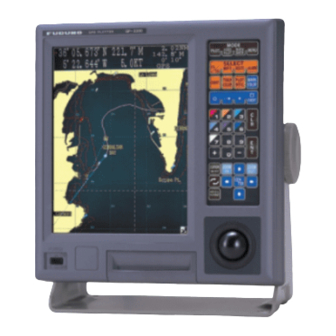
ECONO POWER Power switch Figure 1-4 GD-3300/GP-3300 For the GP-3300, at the first power application after installation, it takes about two minutes to acquire GPS satellite data, called the al- manac. While the unit is acquiring the almanac, the indication “CST”... -
Page 15: The Trackball
1.4 The Trackball 1.5 The Cursor The main function of the trackball is to shift the cursor and the display. The dis- play may be shifted when the cursor is turned off; the cursor when it is turned on. Figure 1-5 Operating the trackball, shifting the picture (cursor off) The cursor functions to •... -
Page 16: Shifting The Display
Note that this function is only available with FURUNO chart cards. You can return the own ship marker to the screen center by pressing the [CENTER] key. This function is only available with FURUNO chart cards. 1.46NM Cursor range 109.8... -
Page 17: Selecting Screen Center By Cursor Position
1.8 Selecting Screen Center by Cursor Position In normal usage your ship is at the screen center. This function is only available with FURUNO chart cards. If you want to select a land feature as the screen center, do the follow- ing: 1. -
Page 18: Chart Scale
1.9 Chart Scale 1.10 Display Brilliance and Key Backlighting The chart scale can be adjusted with the [ZOOM IN] and [ZOOM OUT] keys. Note that the [ZOOM IN] key shrinks the picture, and the [ZOOM OUT] key “blows up” the picture. With a smaller range, you may find that the track appears in tiers. -
Page 19: Card Drives, Chart Cards
2. Insert chart card label side up in the lower slot. Figure 1-11 Inserting chart card 3. Close the card slot door. 4. Press [ZOOM IN] or [ZOOM OUT] key to display chart. This side up. FURUNO NAVIONICS Card Card... - Page 20 Ejecting the chart card Press the eject button. Figure 1-12 Removing chart card Care and handling of the cards • Keep the cards away from direct sunlight, heat sources, and active gases. • Keep cards away from water and chemicals. •...
-
Page 21: Chart Icons
• This icon means the chart is displayed properly; full chart reliability. • This icon means poor chart reliability because chart is overenlarged. FURUNO chart symbols The table below shows FURUNO chart symbols and their meanings. Table 1-3 FURUNO chart symbols Symbol Description Summit Wreck... - Page 22 Comparison of FURUNO, NAVIONICS chart cards Table 1-4 Comparison of FURUNO, NAVIONICS chart cards n i l l i b y t i t i s s f f y r t o i t Buoy, lighthouse data display on NAVIONICS charts NAVIONICS chart cards can show buoy and lighthouse data.
-
Page 23: The Data Window
1.12 The Data Window 1-12 FL (2) Period in seconds (Example: 12 seconds) Number of flashes (Example: 2) : Flashing : Fixed light F FL : Fixed and Flashing light MO : Morse code light Oc : Occulting light Figure 1-15 How to interpret buoy, lighthouse data The data window at the top of the display shows various navigation information. -
Page 24: Display Modes
1.13 Display Modes Data shown when cursor is off DATA DISPLAY (1) YOUR SHIP LAT HEADING YOUR SHIP LON SPEED PLOT DATA DISPLAY (2) YOUR SHIP LAT BEARING TO CHART SCALE DESTINATION YOUR SHIP LON HEADING PLOTTING INTERVAL NAVIGATOR/HDOP Figure 1-17 Information displayed in data window when cursor is off Your plotter has three display modes: Plot, Video Pilot, and Naviga- tion Data. -
Page 25: Menu Operation
1.14 Menu Operation 1-14 Menu operation versus key operation Many functions of your plotter can be executed through the menu or by pressing the key associated with function desired. For example, you can enter a waypoint by pressing the [WPT] key, or [MENU] and [1]. -
Page 26: Main Menu Description
Main menu description Table 1-5 Main menu description s i l s i l n i l n i l t i s y t i t l l l l a , t i l i p . f f n i l / I / s t i... -
Page 27: Operation On The Display
1.15 Operation on the Display DATA INPUT CURSOR This cursor selects location to enter data. ITEM SELECTION CURSOR This cursor, which moves , selects line to select or enter data. 1-16 Selecting items As you move the item selection cursor (red triangle) down through a menu by pressing [ ]/[ ], the option selection cursor, initially col- ored in light-blue, changes to red. -
Page 28: Operational Status Icons
The economy mode turns off the LCD to lessen power consumption (GD-3300: 13 W 6W, GP-3300: 15 W tinually recorded and plotted. To turn the economy mode on press and hold down the [BRILL ECONO] key about three seconds. The lamp on the key lights when the economy mode is on. -
Page 29: Plot Mode Displays
1.18 Plot Mode Displays +36 44.257’ N 140.50 35.92NM Mark cursor 134 40.719’ E 50.5 PLOT +36 44.257’ N 50.5 Cursor latitude 134 40.719’ E 10.0KTS Cursor longitude MARK WAYPOINT PLUS MARK 1-18 Information displayed on the plot display depends on whether the cursor is on or off. - Page 30 Plot display when cursor is off 36 44.257’ N 59.8 Mark cursor 134 40.719’ E 50.5 PLOT 36 44.257’ N 50.5 Ship’s latitude 134 40.719’ E 10.0KTS Ship’s longitude MARK WAYPOINT PLUS MARK Figure 1-21 Plot display, cursor off Bearing to destination 35.92NM 0.10NM GPS 1.2...
-
Page 31: Navigation Data Display
1.19 Setting the Time and Date 1-20 The internal clock marks time and is used to perform navigation cal- culations (for example, time-to-go). Set the clock and the date as fol- lows: 1. Press the [MENU] key. 2. Press the [8] key to display the INITIAL SETTINGS menu. 8 INITIAL SETTINGS VTD AVG TIME = 10MIN... -
Page 32: Track
2.1 Stopping Track Recording When your ship is at anchor or returning to port you probably will not need to record the track. You can stop recording the track, to conserve the track memory, by activating the “hold” function. The track is displayed but not recorded, thereby conserving the track memory. -
Page 33: Track Color
2.2 Track Color 2.3 Changing Color, Appearance of Specific Track The default track color is red, but you may change track color to any one of seven colors. It is useful to change track color when returning to port, changing course, etc. 1. - Page 34 9-1 EDIT TRACK/MARK ITEM = CHG TRACK MODE = CURSOR COLOR = 1 2 3 4 5 6 7 8 (SAME) TYPE = SELECT COLOR AND/OR TYPE. SELECT START AND STOP POINTS BY USING CURSOR, PRESSING ENT AFTER SETTINGEACH POINT. PRESS ENT AGAIN TO CHANGE TRACK.
-
Page 35: Deleting Track
2.4 Deleting Track Deleting track by color One method of deleting unwanted track is by specifying track color. Deleted track cannot be restored – exercise caution when deleting track. 1. Press the [TRACK COLOR] key to display the CHANGE TRACK COLOR menu. CHANGE TRACK COLOR TRK COLOR = 1 2 3 4 5 6 7 SELECT TRACK COLOR BY NUMBER. - Page 36 2. Select DEL TRACK from the ITEM field. 3. Select BOX from the MODE field. 4. Set the top left-hand corner of the box cursor on point A by oper- ating the trackball. 5. Press the [ENT] key. 6. Set the top right-hand corner of the box cursor on point B by operating the trackball.
-
Page 37: Track Plotting Interval
2.5 Track Plotting Interval The plot interval determines how the track will be reconstructed on the display and track storage time. The equipment has two plot inter- vals, plot interval 1 and plot interval 2, which you can set as desired. You can select which one to use by the [PLOT INTVL] key. - Page 38 Setting plot interval 1 by time The default plot method for plot interval 1 is time. To set plot interval 1 by time do the following: 1. Press the [MENU] key. 2. Press the [8] key to select INITIAL SETTINGS. 3.
-
Page 39: Customizing The Hold Function
2.6 Customizing the Hold Function The hold function stops recording the track to conserve track memory. You can customize this functions as below. Turning off track display when track is not being recorded When you stop recording the track in the default setting, the track is displayed but not recorded. -
Page 40: Customizing The Plot Intvl Key
2.7 Customizing the PLOT INTVL Key Each time you press the [PLOT INTVL] key, in the default setting, a plot interval is selected (plot interval 1 or plot interval 2) or recording of the track is turned off. If you do not need one of the plot intervals or you would like to reserve one of them for manual entry of plot interval, do the following: Setup for manually entering plot interval... - Page 41 2-10 4. Select TIME or DISTance. 5. Press the [0] key four times followed by the [ENT] key. Then, when you press the [PLOT INTVL] the plot interval selected above is skipped.
-
Page 42: Marks, Lines
3.1 Entering Marks Marks can be electrically inscribed on the display to denote impor- tant locations. 4,000 marks may be entered, and you have the choice of mark shapes among circle, diamond, square, numeral (1-9), plus mark and minus mark. When the mark memory becomes full no marks can be entered. -
Page 43: Changing Current Mark Color
3.2 Changing Current Mark Color 3. Select the LATITUDE field. Enter latitude. 4. Select the LONGITUDE field. Enter longitude. 5. Press appropriate mark key (1-9). Mark color is available in the colors shown on keys 1-7. When a mark is entered it is inscribed in the color of the cursor mark in the data window at the top of the display. -
Page 44: Changing Shape, Color Of Specific Marks
3.3 Changing Shape, Color of Specific Marks The color and shape of specific marks can be changed as follows: 1. Press [MENU], [9] and [1] to display the EDIT/TRACK MARK menu. 9-1 EDIT TRACK/MARK ITEM = CHG TRACK DEL TRACK CHG MARK DEL MARK MODE = CURSOR BOX ON SCRN OFF SCRN COLOR = 1 2 3 4 5 6 7 8 (SAME) SHAPE=... -
Page 45: Deleting Marks
3.4 Deleting Marks Deleting marks with the cursor 1. Operate the trackball to place the cursor on the mark you want to delete. 2. Press the [CLR] key. If the mark cannot be erased, there may be several marks superim- posed on one another. -
Page 46: External Event Mark
A target mark ( ) shows a radar target’s position. This mark is in- scribed on the GD/GP-3300 when a certain key is pressed on the radar. The following are a few of the FURUNO radars which can output a target mark to the GD/GP-3300: FR-1500 MARK-2 series, FR-1505 MARK-3 series, FR-2805 series, FR-2100 series, FR-2105 series. -
Page 47: Deleting Lines
Entering a line 1. Operate the trackball to place the cursor on position desired for starting point of line. 2. Press [ ] 3. Operate the trackball to place the cursor on the position desired for intermediate (or end) point. 4. -
Page 48: Waypoints
WAYPOINTS In navigation terminology, a particular location is known as a “Waypoint,” whether it be a starting point, a destination point or an intermediate point on a voyage. WAYPOINT 4 WAYPOINT 3 DANGER POINT WAYPOINT 2 WAYPOINT 1 Figure 4-1 Waypoints The GD/GP-3300 series has 98 waypoints into which you can enter position information. -
Page 49: Entering Waypoints
4.1 Entering Waypoints 1 WAYPOINT 1 34 44.555’N 135 23.456’E A B C 1 2 2 34 43.444’N 135 22.445’E 4 34 41.222’N 135 55.221’E 5 34 32.125’N 135 27.658 E Data input 7 33 45.658’N 134 46.265’E cursor 8 33 56.012’N 134 15.456’E ENTER L/L POSITION BY USING CURSOR. - Page 50 4. Enter latitude. Cancel entire line of data: Press the [CLR] key. Change data: Place data input cursor on wrong data, and then reenter data. Switch coordinates: [+] key, changes coordinate to North or East, [-] key, changes coordinate to South or West. 5.
- Page 51 5. Operate the trackball to place the cursor on position desired. 6. Press the [ENT] key. 7. Press the [WPT] key to finish. Waypoint entry at own ship’s position 1. Press the [WPT] key to display the REGISTER WAYPOINT menu. REGISTER WAYPOINT MODE = CURSOR...
-
Page 52: Entering A Comment For A Waypoint
4.2 Entering a Comment for a Waypoint This cursor selects character. 3. Select WPT NO. 4. Enter waypoint number in two digits. 5. Select the RANGE field. 6. Enter range. 7. Select the BEARING field. 8. Enter bearing. 9. Press the [ENT] key to calculate position. The latitude and longi- tude position of the range and bearing entered appears on the display. -
Page 53: Turning Specific Waypoint Displays On/Off
4.3 Turning Specific Waypoint Displays On/Off 4. Press the [ENT] key. (If you enter a wrong character, set the data input cursor on wrong character and then enter correct character.) 5. Repeat steps 2 and 3 to complete comment. 6. Press [ ] to set the cursor out of the comments column and then press the [ENT] key. -
Page 54: Deleting Waypoints
4.4 Deleting Waypoints Turning on/off specific waypoints displays through the waypoint list 1. Press the [MENU] key to display the menu. 2. Press the [1] key to display the WAYPOINT list. 1 WAYPOINT 1 34 44.555 N 135 23.456 E A B C 1 2 2 34 43.444 N 135 22.445 E ’N 4 34 41.222 N 135 55.221 E... -
Page 55: Destination Waypoint
4.5 Destination Waypoint Deleting waypoints through waypoint list 1. Press the [MENU] key followed by the [1] key to display the WAYPOINT list. 2. Select the waypoint you want to delete. 3. Press the [CLR] key. 4. To delete another waypoint, repeat steps 2 and 3. 5. - Page 56 3. Place the cursor on latitude and longitude position desired for destination waypoint. Note that if you place cursor near a mark or a waypoint displayed, cursor position (destination waypoint) is pulled into the mark displayed. 4. Press the [ENT] key Setting destination waypoint by waypoint number 1.
- Page 57 4-10 When you set a destination waypoint... • The DESTINATION SETTING menu disappears. • Destination waypoint is marked with a yellow flag (except desti- nation set by registered waypoints). • Your ship’s position is shown as waypoint 00. • A light-blue dashed line connects your ship’s position with desti- nation waypoint.
- Page 58 Displaying range and bearing to destination waypoint Press the [PLOT] key to display the DATA DISPLAY (2). 36 34.000’ N 176.5 134 20.524’ E 340.5 36 34.000’ N 340.5 DATA DISPLAY (1) 134 20.524’ E 10.0KTS Bearing to destination 14.5NM 0’...
-
Page 59: Cancelling Destination Waypoint
4.6 Cancelling Destination Waypoint 4-12 Once you arrive at your destination you probably won’t need the des- tination waypoint. You can cancel it, three ways. Cancelling destination waypoint through the menu 1. Press the [FR/TO] key to display the DESTINATION SETTING menu. -
Page 60: Route Navigation
ROUTE NAVIGATION In many cases a trip from one place to another involves several course changes, requiring a series of route points (waypoints) which you navigate to, one after another. The sequence of waypoints leading to the ultimate destination is called a route. This unit can automatically advance to the next waypoint on a route, so you do not have to change the destination waypoint repeatedly. -
Page 61: Creating Routes
5.1 Creating Routes TRANSIT ORDER You can create a route three ways: through the route list (by latitude and longitude coordinates), by previously registered waypoints, by cursor. Creating routes through the route list 1. Press the [MENU] key. 2. Press the [2] key to display the ROUTE list. 2 ROUTE WAYPOINT LATITUDE... - Page 62 Creating routes with waypoint numbers: MENU 1. Press the [MENU] key. 2. Press the [2] key to display the ROUTE list. 2 ROUTE ROUTE NO WAYPOINT LATITUDE LONGITUDE 1 (2 8) 3 4 4 5.1 4 6’ N 1 3 5 2 1.2 1 7 E ’...
- Page 63 5. Select WPT NO. 6. Enter waypoint numbers. 7. Press the [ENT] key. Creating routes with the cursor 1. Press the [ROUTE] to display the ROUTE NO. menu. ROUTE NO. MODE = CURSOR WAYPOINT ??? ROUTE NO. = ENTER ROUTE NO., AND SELECT WAYPOINTS, PRESSING + KEY AFTER SELECTIONS.
-
Page 64: Following A Route
5.2 Following a Route Following a route is the process by which you use a stored route for navigation. This unit displays navigation information to guide you from one waypoint to the next, as it automatically switches from waypoint to waypoint in sequence. 1. -
Page 65: Temporarily Deselecting A Route Waypoint
5.3 Temporarily Deselecting a Route Waypoint that takes you through a seawall or over land! It is far better to leave a reasonable arrival alarm range of say 0.1 nautical miles, and when you get as close as safely possible to the desired waypoint which is now blocked then manually override the route planning mode and go to manual waypoint sequencing. -
Page 66: Deleting Route Waypoints
Cursor Minus sign (waypoint deselected) 5.4 Deleting Route Waypoints 2 ROUTE WAYPOINT LATITUDE (06) 34 21.185’ (05) 34 24.068’ (04) 35 31.254’ (03) 36 18.314’ (02) 37 33.568’ (01) 38 01.438’ Figure 5-8 ROUTE list 6. Press [-]. In the figure above waypoints 1, 2, 3 and 4 are dese- lected. -
Page 67: Cancelling Route Navigation
5.5 Cancelling Route Navigation Deleting all route waypoints 1. Press the [ROUTE] key. 2. Select WAYPOINT. 3. Select ROUTE NO. 4. Enter route number. 5. Select WPT NO. 6. Press the [CLR] key followed by the [ENT] key. You can cancel route navigation as follows: 1. -
Page 68: Route Calculation
5.6 Route Calculation The route calculation function provides distance and time-to-go cal- culations between each route waypoint. 1. Press the [MENU] key. 2. Press the [2] key to select ROUTE. 2 ROUTE WAYPOINT LATITUDE LONGITUDE ’ N ’ N ’ N ’... -
Page 69: Alarms
Note: The alarms are useful for alerting you to possibly dangerous situations. However, the captain is always responsible for the safe operation of his ship. FURUNO Electric Company will assume no responsibility for any damages associated with the use of the alarms. -
Page 70: Anchor Watch Alarm
2. Place the cursor on the ARR/ANCHOR field. 3. Select ARRival. 4. Press [ ] to select ALARM RANGE. 5. Enter alarm range. To enter 0.05 nautical miles, for example, press [0], [0], [5] and [0]. 6. Press the [ENT] key. Red dashed line (Arrival alarm) Figure 6-3 Alarm range of arrival alarm... -
Page 71: Xte Alarm, Border Alarm
6.2 XTE Alarm, Border Alarm XTE alarm The XTE (cross-track error) alarm alerts you when your ship strays from its intended course. You may preset the alarm limit from 0.01 nautical miles to a maximum lane width of 99.99 nautical miles. The alarm will be released when your ship goes out of the lane limits. -
Page 72: Ship's Speed Alarm
6.3 Ship’s Speed Alarm If you want to set a border alarm between waypoints 77 and 78 (must be preregistered) with an alarm range of 0.3 nautical miles, do the following: 1. Press the [FR/TO] key to display the DESTINATION SETTING menu. -
Page 73: When The Alarm Buzzer Sounds
1. Press the [ALARM] key to display the ALARM menu. 2. Select SPEED. 3. Select IN or OUT. 4. Select UPPER LIMIT. 5. Enter desired upper limit. 6. Select LOWER LIMIT. 7. Enter desired lower limit. 8. Press the [ENT] key. 6.4 When the Alarm Buzzer Sounds... -
Page 74: Video Pilot Display, Navigation Data Display
VIDEO PILOT DISPLAY, NAVIGATION 7.1 Video Pilot Display Features The video pilot display shows navigation information about your destination, using a course-up presentation. To display the video pi- lot display, press the [VIDEO PILOT] key. Figure 7-1 shows a typi- cal video pilot display. - Page 75 Table 7-1 Comparison of video pilot and plot displays Destination data Velocity-To-Destination (VTD) Velocity to destination is the amount of speed in the direction of the desired destination. Figure 7-2 Velocity-to-destination Time-To-Go (TTG) Time-to-go is the amount of time in hours and/or minutes to arrive at your destination, using present course and speed.
- Page 76 Comparison of plot and video pilot displays Grid shows latitude and longitude. PLOT DISPLAY Grid shows distance. Note: When NAVIONICS chart is used, the chart data disappears at this mode, except bearing of the destination is 0 degrees. VIDEO PILOT DISPLAY 34 44.463’...
-
Page 77: Navigation Data Display
7.2 Navigation Data Display The navigation data display provides various navigation information, input by a navigation aid and sensors. You can display it by pressing the [NAV DATA] key. NAV DATA 10 - APR - 1998 03 : 02 : 22 34 44. -
Page 78: Autopilot Data
This chapter describes what information you receive with autopilot connection. The following features are available with autopilot (for example, FURUNO FAP-330) connection: • The FAP-330 feeds autopilot information to the GD/GP-3300 for display on the plot and video pilot displays. -
Page 79: Autopilot Information On Plot Display
8.2 Autopilot Information on Plot Display Autopilot information (Autopilot FAP-330 in NAV Mode) (FAP-330 in AUTO mode) (FAP-330 in MANUAL mode) 36 44.257’ N 340.5 134 40.719’ E 10.0KTS Own ship marker CRS SET MODE 356.0 357.0 MODE CRS SET AUTO 356.0 357.0... -
Page 80: Autopilot Information On Video Pilot Display
8.3 Autopilot Information on Video Pilot Display 36 44.257’ N 340.5 134 40.719’ E 0.50 0.50 0.50 O 09:56 O 09:56 0.01NM 0.01NM MODE 356.0 Figure 8-3 Sample autopilot information on video pilot display 1.46NM 109.8 10.0KTS 0.10NM 10.1 CRS SET CRS ERR 357.0 0.01NM... - Page 81 Autopilot on, no destination waypoint selected MODE HDG (T) 358.0 (a) Autopilot in MANUAL mode MODE AUTO 356.0 (b) Autopilot in AUTO mode T : True Bearing M : Magnetic Bearing Figure 8-4 Autopilot information when autopilot is on, no destina- tion waypoint selected Course set Destination...
- Page 82 Autopilot on, destination waypoint selected MODE 356.0 (a) Autopilot in MANUAL mode 10.1 MODE AUTO 356.0 (c) Autopilot in AUTO mode MODE 356.0 (c) Autopilot in NAV mode Figure 8-6 Autopilot information when autopilot is on, destination waypoint selected Autopilot on, mark entered, destination waypoint selected 14 : 51 14 : 30 32.06NM...
-
Page 83: Memory Card Operations
MEMORY CARD OPERATIONS 9.1 Formatting Memory Cards Before you can save information to a memory card you must prepare its surface by formatting it. Formatting is a routine procedure you must perform on new cards before you can use them with this unit. You have to initialize them only once. -
Page 84: Saving Data To Memory Cards
9.2 Saving Data to Memory Cards 4. Press the [8] key to select FORMAT MEMORY CARD. 5. Press the [ENT] key. “FORMATTING” appears on the display during formatting. “FOR- MATTING COMPLETED” appears upon completion of formatting. If the card could not be formatted, “FORMATTING FAILED” ap- pears. - Page 85 3-1 SAVE TRACK 00 CREATE NEW FILE TOTAL NO. OF FILES = 0 Data input cursor SELECT FILE TO BE SAVED USING ENTER FILE NAME BY USING TRACKBALL. SET CURSOR ON OK BY USING TRACKBALL. PRESS ENT TO SAVE. Figure 9-4 SAVE TRACK display 5.
-
Page 86: Playing Back Memory Cards
[ENT] key after selecting each charac- ter. When you have finished entering the file name, select OK. If you want to enter file name “FURUNO 1”, for example, do the following: 1. Place the cursor on “F” by operating the trackball. -
Page 87: Saving, Playing Back Initial Settings
9.4 Saving, Playing Back Initial Settings 3. Press the [5] key to select DISPLAY MEMORY CARD. 5 DISPLAY M. C. 00 TRACK 01 1 2 3 4 5 6 7 8 9 0 1 2 3 4 56 02 MARK Figure 9-7 DISPLAY M.C. -
Page 88: Editing Memory Cards
9.5 Editing Memory Cards Adding track, marks/lines 1. Press [MENU], [7] and [2] (track) or [3] (marks/lines) to confirm that there is sufficient memory remaining on the display. 2. Press the [MENU] key. 3. Press the [4] key to select LOAD MEMORY CARD. 4. -
Page 89: Gps Information On The Navigation Data Display
GPS RECEIVER OPERATION (GP-3300) 10.1 GPS Information on the Navigation Data Display The navigation data display, which is displayed with the [NAV DATA] key, shows GPS information, as well as navigation data. Position fixing mode NAV DATA 10 -APR -˚1998 03 : 02 : 22 34 44. -
Page 90: Frequency Deviation
Table 10-1 GPS indications on the navigation data display t s i a l i n i l i l l x i f s t i t i s x i f 10-2 r i f i l l n i l t i l l n i l... -
Page 91: Gps And Dgps Initial Settings
10.2 GPS and DGPS Initial Settings Satellite data Satellite data is shown as follows: Satellite no. MODE: Satellite receiving condition (TRK, Now tracking; USE, Using for position fixing) ELV: Satellite elevation angle AZM: Satellite azimuth (bearing) LVL: Signal level (200 or better to get position fixes) This section provides the information necessary for entering GPS initial settings. - Page 92 t i s t i s x i f t i s i l l y l l c i l y l l 10-4 GPS initial settings menu description Table 10-2 describes the GPS INITIAL SETTINGS menu. Table 10-2 Description of GPS INITIAL SETTINGS menu t i s x i f x i f...
-
Page 93: Satellite Force Health/Deselection
x i f i l l F “ 10.3 Satellite Force Health/Deselection Satellite condition (NONE, No satellite; OK, Satellite in use; NG, No Good) 01 : NONE ( 04 : NONE ( 07 : NONE ( 10 : NONE ( 13 : OK 16 : OK 19 : OK... -
Page 94: Gps Smoothing
10.4 GPS Smoothing SPEED (KNOT) 10-6 2. Enter satellite number using two digits. 3. Press the [ ] key to display desired option. Each press of the key deletes item in parentheses (namely, enables the satellite) or displays DESELECT or FORCED. 4. - Page 95 Setting GPS smoothing The default GPS smoothing settings are suitable for most all condi- tions. If change of the default settings is necessary, do the following 1. Press [MENU] and [8], and then press [ ] to set the cursor on PAGE CHANGE (TO GPS INITIAL SETTINGS).
-
Page 96: Cold Start
10.5 Cold Start 10-8 Cold start is automatically executed at initial power application or when the GPS memory is cleared. This is done to acquire the Alma- nac to receive a GPS satellite. You can also do the cold start manually when the Almanac is too old to acquire a satellite;... -
Page 97: Geodetic Datum
10.6 Geodetic Datum 10.7 Correcting GPS Position 8. Press the [NAV DATA] key to display the navigation data dis- play. The indication “CST” appears at the top of the display. When cold start is completed, “CST” is replaced by “2D” or “ACQ.” Cold start takes about two minutes to complete. -
Page 98: Other Functions
11.1 Displaying Position in Loran TDs 135 21.465’ E 1.9KTS OTHER FUNCTIONS You can display own ship’s position and cursor position in Loran A or Loran C TDs, as well as latitude and longitude. This function does not require connection of a Loran receiver; Loran chain information is stored in the unit. -
Page 99: Bearing Display Reference
11.2 Bearing Display Reference 11-2 3. Select LA. 4. Select STATION PAIR, and station pair codes list appears. 00: 1L0 01: 1L1 05: 1L7 06: 1S1 10: 1S6 11: 2H3 15: 2S0 16: 2S1 20: 2S5 21: 2S6 5. Enter station pair codes. 6. -
Page 100: Magnetic Deviation
11.3 Magnetic Deviation Displaying true bearing 1. Press [MENU] and [8]. 8 INITIAL SETTINGS LINE (HOLD PLOT) MAGNETIC DEVIATION = AUTO (07 W) MAN (06 E) (0~99) BEARING COURSE VECTOR MARK SIZE Figure 11-3 INITIAL SETTINGS menu 3. Select BEARING. 4. -
Page 101: Changing Chart Appearance
This section describes how to change chart appearance, for example, change color and brightness of background, turn grid lines on or off, etc. This is applicable to both FURUNO and NAVIONICS chart cards. 1. Press the [CHART] key to display the GEODETIC DATUM menu. -
Page 102: Correcting Chart Position
11.5 Correcting Chart Position There may be some instances where the chart latitude and longitude position are off by some seconds. You can compensate for this error. You may correct chart position three ways: by cursor, by latitude and longitude, by Delta L/L. When you apply an offset to chart position the L/L icon appears at the bottom right-hand corner on the display. - Page 103 11-6 Correcting chart position by latitude and longitude You can correct chart position by manually entering latitude and lon- gitude corrections. 1. Press the [MENU] key followed by the [6] key to display the CORRECT POSITION screen. 6 CORRECT POSITION POS CORR = YES MODE = CURSOR...
-
Page 104: Loran Td Correction
11.6 Loran TD Correction 2. Select YES from the POS CORR field. 3. Select L/L from the MODE field. 4. Enter latitude and longitude correction values. 5. Press the [ENT] key. Cancelling chart position correction 1. Press [MENU] and [6]. 2. -
Page 105: Calculating R/B Between Two Points
11.7 Calculating R/B Between Two Points 9-2 CALCULATE RANGE/BEARING MODE START PT : STOP PT : RANGE ENTER L/L START AND STOP POINTS. PRESS CLR TO CALCULATE ANOTHER R/B. 11-8 You can calculate the range and bearing between any two points. Three methods are available: by latitude and longitude, by cursor, and by waypoint numbers. - Page 106 Calculating R/B by latitude and longitude You can calculate the range and bearing between two points by using the cursor to designate the two points. 1. Press [MENU], [9] and [2] to display the CALCULATE RANGE/ BEARING menu. 9-2 CALCULATE RANGE/BEARING MODE = CURSOR START PT :...
-
Page 107: Locking Preferred Settings
11.8 Locking Preferred Settings 11.9 Memory Capacity 11-10 2. Select WAYPOINT from the MODE field. 3. Enter start and stop waypoints by using arrow keys and numeric keys. 4. Press the [ENT] key. The calculation results appear on the menu. The GD/GP-3300 provides various methods for entering and select- ing destination waypoint, waypoint and other items. - Page 108 The track and memory capacity includes current or loaded track and current or loaded marks. • Current track: Position input by navigator • Current mark: Mark input through keyboard • Loaded track/mark: Track/mark loaded from a memory card Note: Waypoints loaded from a memory card are erased if they share the same waypoint numbers as current waypoints.
-
Page 109: Apportioning The Memory
11.10 Apportioning the Memory 11-12 Mark/line memory When the mark memory becomes full no marks can be entered. 1600 pts 2800 pts New Marks Current Marks Figure 11-17 What happens when the mark memory becomes full and new marks are entered 1800 pts 1600 pts played back... -
Page 110: Reading Number Of Track, Marks Used
11.11 Reading Number of Track, Marks Used 7-1 APPORTION MEMORY TRACK MEM. = 4000 PTS (MAX 8000PTS) CURRENT APPORTION TRACK : MARK MEMORY APPORTION CHANGE DELETE TRACKS AND ALL MARKS. ENTER DESIRED MAXIMUM NO. OF TRACK POINTS. MAXIMUM NO. OF MARKS = 8000 - MAXIMUM NO. OF TRACK POINTS. CHANGING MEMORY APPORTION DELETES ALL EXISTING TRACKS AND MARKS. -
Page 111: Smoothing
11.12 Smoothing 0-6 : Position from navaid 0-6 : Position with smoothing applied 11-14 In Figure 11-21, the actual ship’s track is shown by a wide hatched arrow and the position being fed from the navigational aid is shown by black dots. If smoothing is selected to “0 (off),” the track shown on the display will be a irregular track plotting (solid line) due to signal variations. -
Page 112: Selecting Navaid
11.13 Selecting Navaid Navigation data can be fed from the internal GPS receiver (GP-3300 only) or external navigator. The default navaid setting for the GP- 3300 is the internal GPS receiver. To select an external navaid; 1. Press [MENU] and [8] to display the INITIAL SETTING menu. 8 INITIAL SETTINGS PAGE CHANGE (TO GPS INITIAL SETTINGS) INTERNAL NAV... -
Page 113: Track, Mark And Marker Attributes
134 40.719’ E 10.0KTS Time mark Figure 11-24 Items whose attributes you can change on the INITIAL SETTINGS and SPECIAL menus Unit of range 1.46NM 109.8 measurement 0.10NM Type of course vector Sector information (lighthouse viewing angle, FURUNO charts) Type of cursor... - Page 114 Initial settings menu 8 INITIAL SETTINGS LINE (HOLD PLOT) MAGNETIC DEVIATION = AUTO (07 W) MAN (06 E) (0~99) BEARING COURSE VECTOR MARK SIZE CURSOR SIZE OWN SHIP MARK TRACK WIDTH RANGE UNIT VTD AVG TIME DATE TIME EXTERNAL CLOCK AUTOPILOT DISPLAY TD INDICATION Figure 11-25 INITIAL SETTINGS menu...
- Page 115 11-18 The tables on the next page explain the display screen-related items on the INITIAL SETTINGS and SPECIAL menus. Table 11-1 Customizable items on the INITIAL SETTINGS menu l l a y l l n i l o l i Table 11-2 Customizable items on SPECIAL menu g i l t i s...
-
Page 116: Chart Symbols, Contour Lines Attributes
11.15 Chart Symbols, Contour Lines Attributes You can change the color of chart symbols (wreck, beacon, etc.) and style and color of contour lines as follows: 1. Press [MENU], [9] and [7] to display the SELECT MARKS/ CONTOUR LINES menu. 9-7 SELECT MARKS/CONTOUR LINES PEAK SHIP WRECK=... -
Page 117: Maintenance And Troubleshooting
MAINTENANCE & TROUBLESHOOTING 12.1 Preventive Maintenance Regular maintenance is important for good performance. Following the procedures set forth in this chapter will help keep your unit in top operating condition for many years to come. WARNING WARNING ELECTRICAL SHOCK HAZARD Do not open the equipment. -
Page 118: Diagnostic Tests
12.2 Diagnostic Tests 12-2 The display unit incorporates several diagnostic tests which check the system for proper operation. Self test at power on Each time you turn on the power all devices and the internal battery are checked for proper operation. The display shows the results of the check as OK (normal) or NG (No Good). -
Page 119: Keyboard Test
4. Press the [1] key to select MEMORY•I/O PORT. Then, the unit checks each memory circuit and I/O port one by one, displaying the results after each checking each item. 9-9-1 MEMORY TEST Asterisk marks *ROM item currently SRAM being tested. VRAM MEMORY CARD INTERNAL BATTERY... - Page 120 1. Press [MENU], [9], [9] and [3] to select TEST PATTERN 1. The display should look like Figure 12-5. GP-3300 FURUNO ELECTRIC CO., LTD Figure 12-5 Test pattern 1 2. Check the pattern for color dropout. 3. Press any key to escape.
-
Page 121: Error Messages
12.3 Error Messages The following is an alphabetical listing of error messages which may appear on the display along with an explanation of what they mean and what to do when they appear. Cannot be deleted together. Cannot delete both current track and loaded track together by the cursor. - Page 122 12-6 Could not save. Try again? • Memory card write protected. • ROM card inserted instead of memory card. • Memory card is full. Data error. • No data entered in waypoint selected. • No data entered in route selected. •...
-
Page 123: Replacement Of Fuse
12.4 Replacement of Fuse Waypoint already used. Waypoint being used as destination waypoint. Waypoint area is full. No free waypoint area when waypoint registered without enter- ing waypoint number. Waypoint number already exists. L/L position of waypoint entered as route point matches L/L po- sition of a registered waypoint. -
Page 124: Replacement Of Batteries
12.5 Replacement of Batteries 12-8 Both the GDC Board inside the display unit and the memory cards use a battery to store information. The life of these batteries is about three years. When the voltage of a battery is low, the “battery” icon appears on the display. -
Page 125: Verifying Program Version No
12.6 Verifying Program Version No. 8 INITIAL SETTINGS SELF TEST PROGRAM NO. : 14517020 xx 8 INITIAL SETTINGS : SELECT ITEM : SELECT PARAMETER PROGRAM NO. : 48501050 xx The procedure which follows shows how to verify the program ver- sion no. -
Page 126: Troubleshooting Table
12.7 Troubleshooting Table . . . s t l n i l y l t 12-10 The section provides a troubleshooting table which the user can fol- low to identify and resolve operating problems. In most cases the cause of operating problems is simple; wrong key pressed, loosened connection, etc. - Page 127 . . . n i l i t s (Continued on next page) . . . • • • • t n i • • • • • • c i t c i t • • • • . l l t i s i t l y l t...
-
Page 128: Clearing Memories
• • • Both the GD-3300 and GP-3300 have GD and display screen memo- ries. The GP-3300 also has the GP memory. Memories can be cleared to start fresh operation. When you clear a memory the equipment automatically restores default settings for the memory cleared. - Page 129 2. Press the [9] key to select MISC. 9 MISC 1 EDIT TRACK/MARK 2 CALCULATE RANGE/BEARING 6 SPECIAL 7 SELECT MARKS/CONTOUR LINES 8 CLEAR MEMORY 9 SELF TEST SELECT NUMBER. Figure 12-10 MISC menu 3. Press the [8] key to select CLEAR MEMORY. 9 - 8 CLEAR MEMORY 1 CLEAR SCREEN DATA 2 CLEAR ALL GD DATA...
-
Page 130: Appendix
APPENDIX Time Differences... -
Page 131: Geodetic Chart List
Geodetic Chart List 001: WGS84 002: WGS72 003: TOKYO : Mean Value (Japan, Korea & Okinawa) 004: NORTH AMERICAN 1927 : Mean Value (CONUS) 005: EUROPEAN 1950 : Mean Value 006: AUSTRALIAN GEODETIC 1984 : Australia & Tasmania 007: ADINDAN : Mean Value (Ethiopia &... -
Page 132: Specifications
SPECIFICATIONS OF COLOR VIDEO PLOTTER/COLOR GPS PLOTTER 1. GENERAL (1) Display (2) Projection (3) Usable Area (4) Display Mode 2. GPS RECEIVER (GP-3300 ONLY) (1) Receiving Channels (2) Rx Frequency (3) Rx Code (4) Position Fixing System (5) Position Accuracy (6) Tracking Velocity (7) Position-fixing Time 3. - Page 133 8. COATING COLOR (1) Display Unit Ship’s speed in and out alarms FURUNO chart card or NAVIONICS chart card available Ship’s L/L position (Loran C or A TDs also available) Date and Time, Ship’s speed, Chart scale, Waypoint L/L position,...
-
Page 134: Index
11-4 land color 11-4 land density 11-4 lighthouse sector data 11-19 place-name indication 11-4 symbol color 11-19 symbols (FURUNO cards) 1-10 troubleshooting 1-9 CLR key 6-5 Cold start (GPS receiver) 10-8 Color distortion test 12-4 Color dropout test 12-4... - Page 135 Lines changing color 3-6 deleting all 3-6 deleting individual points on a line 3-6 entering 3-6 Loran TDs correcting position 11-7 Loran A TDs display 11-1 Loran C TDs display 11-2 Magnetic deviation 11-3 Maintenance preventive 12-1 replacement of batteries 12-8 replacement of fuse 12-7 Marks changing color of past-entered marks 3-3...
- Page 136 Video pilot display 7-1–7-3 VIDEO PILOT key 1-13 Waypoints cancelling destination waypoint thru keyboard 4-12 cancelling destination waypoint thru menu 4-12 comments 4-5 deleting by cursor 4-7 deleting external waypoint 4-8 deleting through waypoint list 4-8 entering at own ship's position 4-4 entering by cursor 4-3 entering by latitude and longitude 4-2 entering by navigation aid 4-5...
Need help?
Do you have a question about the GD-3300 and is the answer not in the manual?
Questions and answers