Table of Contents
Advertisement
Electronic copies of the most current TSM issue can be found on the Viking Pump website at www.vikingpump.com
CONTENTS
Introduction
Safety Information
Special Information
Maintenance
Disassembly: Pump
Disassembly: Coupling
Disassembly & Assembly
of MD-C Series Bearing Housing
Installation of Bushings
Assembly: Coupling
Adjusting Head Gasket End Clearance
Pump Rotation
Pressure Relief Valve
Troubleshooting
Warranty
WARNING !
Persons with surgical implants of a
metallic or electronic nature should
avoid working on pump – especially the
inner magnet assembly.
INTRODUCTION
The illustrations used in this manual are for identification
purposes only and should not be used for ordering parts
Secure a parts list from the factory or a Viking® representative
Always give complete name of part, part number or material
with model number and serial number of pump when ordering
repair parts The unmounted pump or pump unit model
number and serial number can be found on the nameplate
In the Viking® model number system, the basic size letters
are combined with the series (823, 825, 827), indicating basic
pump construction material (steel, cast iron, or stainless steel
respectively) See Model Number Chart.
VIKING PUMP, INC.
VIKING PUMP, INC.
TECHNICAL SERVICE MANUAL
1
2
3
3
4
6
8
10
10
11
11
11
13
14
•
•
A Unit of IDEX Corporation
A Unit of IDEX Corporation
MAGNETIC DRIVE PUMPS
SERIES 823 – STEEL
825 – CAST IRON
827 – STAINLESS STEEL
SIzES K & KK
Model Number Chart
UNMOUNTED
Units
unmounted pump model numbers
K-823 , 825 , 827
followed by a letter(s) indicating
drive style
B = Bracket Mount
R = Viking Reducer Drive
KK823 , 825 , 827
P = Commercial Speed Reducer
(Example: KK-827-MD-C80R)
TABLE 1
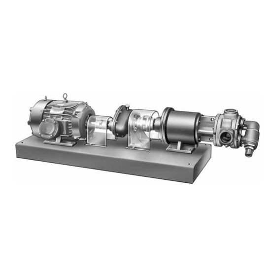
This manual deals only with Series 823, 825 and 827 magnetic
drive pumps and couplings Refer to Figures 1 thru 23
for general configuration and nomenclature used in this
manual Pump specifications and recommendations are
listed in Catalog Section 845
K & KK-827 (stainless steel) MD-C80 B
Bearing Carrier, Footed Bracket and
Mounted Pump with Flanged Ports.
K & KK-825 (cast iron) MD-C80 R
Unit complete with Motor, "B"
Gear Reducer, Bearing Carrier
mounted to base with Mounted
Pump featuring Tapped Ports.
•
•
Cedar Falls, IA 50613 USA
Cedar Falls, IA 50613 USA
SECTION
TSM 845
PAGE
1 Of 14
ISSUE
f
UNITS
are
designated
by
the
FIGURE 1
FIGURE 2
Advertisement
Table of Contents

Subscribe to Our Youtube Channel
Related Manuals for Viking pump KK-827


Summary of Contents for Viking pump KK-827
- Page 1 Electronic copies of the most current TSM issue can be found on the Viking Pump website at www.vikingpump.com TECHNICAL SERVICE MANUAL SECTION TSM 845 MAGNETIC DRIVE PUMPS SERIES 823 – STEEL PAGE 1 Of 14 825 – CAST IRON ISSUE 827 –...
-
Page 2: Safety Information
SAFETY INFORMATION INCORRECT INSTALLATION, OPERATION OR MAINTENANCE OF EQUIPMENT MAY CAUSE SEVERE PERSONAL INJURY OR DEATH AND/OR EQUIPMENT DAMAGE AND MAY INVALIDATE THE WARRANTY. This information must be read fully before beginning installation, operation or maintenance and must be kept with the pump. All installation and maintenance must be undertaken by suitably trained or qualified persons only. -
Page 3: Special Information
SPECIAL INFORMATION DISCHARGE DANGER ! Before opening any Viking pump liquid chamber (pumping chamber, reservoir, etc.) Be sure: SUCTION 1. That any pressure in the chamber has been completely vented through the suction or discharge lines or other appropriate openings or connections. -
Page 4: Disassembly: Pump
DANGER ! will facilitate inspection, adjustment and repair work STORAGE: If pump and coupling are to be stored, drain pump Before opening any Viking pump liquid and pour non-detergent SAE 30 weight oil into the pump port chamber (pumping chamber, reservoir, Apply grease to the pump or the coupling shaft extension, if etc.) Be sure:... - Page 5 Remove head from pump Do not allow idler to fall from Mark the location and orientation of the Balance plate before removing by pulling out (The balance plate may idler pin Tilt top of head back when removing to prevent this Avoid damaging head gasket set, all gaskets are not be removable in the 825 series) required to maintain end clearance...
-
Page 6: Disassembly: Coupling
ITEM NAME OF PART ITEM NAME OF PART ITEM NAME OF PART Capscrews Ball Bearing (2 Req’d) Bracket External Snap Ring Internal Snap Ring Canister Bearing Housing Inner Magnet Assembly Bearing Spacer Outer Mag Assembly Hand Knobs FIGURE 6 MD-C SERIES COUPLING DISASSEMBLY: COUPLING CAUTION ! SERIES MD-C80 COUPLING... - Page 7 Insert a brass bar through a port between two rotor teeth CAUTION ! and loosen the capscrew holding the inner magnet to the shaft (See Figure 11). Do not forget, this is a very Do not attempt to pull the magnet sets strong magnet If pump disassembly is required, remove apart by hand until the outer has been the external retaining ring...
-
Page 8: Disassembly & Assembly Of Md-C Series Bearing Housing
DISASSEMBLY & ASSEMBLY OF PRESS MD-C SERIES BEARING HOUSING DISASSEMBLY The bearing housing features two sealed ball bearings along with an outer magnet assembly If further disassembly of this unit is required, proceed as follows: Refer to Figure 12 for part identification Cover the open end of the outer magnet with a piece sheet metal or cardboard This will keep foreign material out of magnet area Set the assembly face down with the shaft pointing... -
Page 9: Assembly: Pump
ASSEMBLY: PUMP If old gaskets are not reusable, refer to “Adjusting Head Gasket End Clearance” on page 10. Otherwise, Use a suitable lubricant compatible with the fluid being place the head gaskets on the head The proper amount handled when reassembling the pump of gaskets should be used to provide the correct end clearance Table 2 gives the quantity of gaskets available Inspect all parts, especially drilled holes in casing for the suck... -
Page 10: Installation Of Bushings
INSTALLATION OF BUSHINGS Inspect canister O-ring for signs of wear and replace if necessary Slide canister over inner magnet and press CARBON GRAPHITE: over O-ring until canister meets the pump mounting flange When installing carbon graphite bushings, extreme care must Support the pump from overhead and secure coupling be taken to prevent breaking Carbon graphite is a brittle... -
Page 11: Pump Rotation
ADJUSTING HEAD GASKET PUMP ROTATION END CLEARANCE The pump is designed to take fluid from the discharge side of the pump and channel it down the idler pin into the shaft Use either of the following procedures to properly adjust the and out into the canister through the capscrew which secures end clearance when replacing gaskets: the inner magnet The fluid is returned through a hole in... -
Page 12: Pressure Relief Valve
Relief valve adjusting screw cap must always point towards Before opening any Viking pump liquid suction side of pump If pump rotation is reversed, remove chamber (pumping chamber, reservoir, relief valve and turn end for end Refer to Figure 3, page 2. -
Page 13: Troubleshooting
TROUBLESHOOTING PUMP INFORMATION Some of the following may help pinpoint the problem: Pump Model Number: Pump does not pump: ► Lost its prime from air lead or low level in tank Serial Number: ► Suction lift too high ► Rotating in wrong direction ►... -
Page 14: Warranty
WARRANTIES ARE EXPRESSLY EXCLUDED. it should contact a local engineering firm with monitoring experience See complete warranty at www.vikingpump.com. • • © 3/2013 Viking Pump Inc. VIKING PUMP, INC. A Unit of IDEX Corporation Cedar Falls, IA 50613 USA All rights reserved...
Need help?
Do you have a question about the KK-827 and is the answer not in the manual?
Questions and answers