Table of Contents
Advertisement
Quick Links
VISIT VIKINGPUMP.COM FOR PDF OF CURRENT TSM ISSUE & TO VIEW REPAIR VIDEOS
TECHNICAL SERVICE MANUAL: INSTALLATION, OPERATION & MAINTENANCE
TABLE OF CONTENTS
Model Number Chart ........................................................................1
Introduction ......................................................................................1
Safety Information & Instructions .....................................................2
Special Information ..........................................................................3
Rotation ........................................................................................3
Circulation Lines ...........................................................................3
Suckback & Flush Holes ..............................................................3
Jacketed Ports .............................................................................3
Pressure Relief Valves .................................................................3
Mechanical Seals .........................................................................3
Maintenance .....................................................................................3
Lubrication ....................................................................................3
Packing Adjustment .....................................................................3
Cleaning Pump .............................................................................4
Storage .........................................................................................4
Suggested Repair Tools ...............................................................4
Removal: Cartridge Mechanical Seal ..............................................7
Installation: Cartridge Mechanical Seal ...........................................7
Removal: Component Mechanical Seal ..........................................8
Installation: Component Mechanical Seal .......................................8
Removal: Behind the Rotor Mechanical Seal ..................................9
Installation: Behind the Rotor Mechanical Seal ...............................9
Guard Seal ........................................................10
®
Guard Seal .....................................................10
®
Removal: Packing .......................................................................... 11
Installation: Packing ....................................................................... 11
Pump Disassembly ........................................................................ 11
Pump Assembly .............................................................................13
Pump Flange Assembly .................................................................14
Thrust Bearing Adjustment ............................................................14
Installation: Carbon Graphite Bushings .........................................15
Bracket Bushing Installation: Stuffing Box Seals .............................15
Bracket Bushing Installation: Behind the Rotor Seal .......................15
Pressure Relief Valve Instructions .................................................16
Disassembly ...............................................................................16
Assembly ....................................................................................16
Pressure Adjustment ..................................................................16
Important Ordering Information ..................................................16
...........................................................17
General Installation Notes ..............................................................17
Foundation .....................................................................................18
Component & Unit Lifting Features ...............................................18
Alignment .......................................................................................20
Piping .............................................................................................20
Start Up ..........................................................................................21
Troubleshooting .............................................................................22
Vacuum Gauge - Suction Port ...................................................22
Pressure Gauge - Discharge Port ..............................................22
Rapid Wear ...................................................................................23
Preventative Maintenance .............................................................24
Do's & Don'ts .................................................................................24
Installation ..................................................................................24
Operation....................................................................................24
Maintenance ...............................................................................25
ESB-515 .........................................................................................25
Lubrication of Viking Pumps ......................................................25
Lubrication of Viking Reducers ..................................................25
Lubrication of Viking Associative Equipment .............................25
UNIVERSAL PRODUCT LINE: STAINLESS STEEL
127C SERIES™, 1127C SERIES™, 4127C SERIES™,
227C SERIES™, 1227C SERIES™, 4227C SERIES™
SIZES: H, HL, K, KK, L, LL, LS, Q, QS
© 2024 Viking Pump, Inc. • Cedar Falls, IA
MODEL NUMBER CHART
NON-JACKETED
O-Pro
Mech.
®
Packed
Guard Seal
Seal
H127C
H1127C
H4127C
HL127C
HL1127C
HL4127C
K127C
K1127C
K4127C
KK127C
KK1127C
KK4127C
L127C
L1127C
L4127C
LL127C
LL1127C
LL4127C
LS127C
LS1127C
LS4127C
Q127C
Q1127C
Q4127C
QS127C
QS1127C
QS4127C
INTRODUCTION
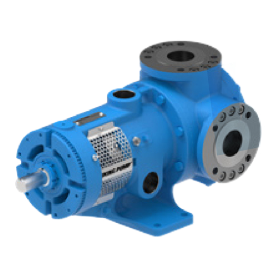
The illustrations used in this manual are for identification
purposes only and cannot be used for ordering parts.
Obtain a parts list from your Viking Pump
Always give a complete name of part, part number and
material with the model number and serial number of pump
when ordering repair parts. The unmounted pump or pump
unit model number and serial number are on the nameplate.
This manual only applies to the pump models specified in the
"Model Number Chart" on page 1. Pump specifications and
recommendations are listed in the Catalog Sections, which
are available at vikingpump.com.
FIGURE 1: H, HL SIZES
(HL127C SHOWN)
FIGURE 3: L, LL, LS SIZES
(LL127C SHOWN)
TSM
2700
Page
1 of 26
Issue
A
JACKETED
O-Pro
Mech.
®
Packed
Guard Seal
Seal
H227C
H1227C
H4227C
HL227C
HL1227C
HL4227C
K227C
K1227C
K4227C
KK227C
KK1227C
KK4227C
L227C
L1227C
L4227C
LL227C
LL1227C
LL4227C
LS227C
LS1227C
LS4227C
Q227C
Q1227C
Q4227C
QS227C
QS1227C
QS4227C
representative.
®
FIGURE 2: K, KK SIZES
(KK1227C SHOWN)
FIGURE 4: Q, QS SIZES
(QS4227C SHOWN)
Advertisement
Table of Contents

Subscribe to Our Youtube Channel
Related Manuals for Viking pump H127C


Summary of Contents for Viking pump H127C
-
Page 1: Table Of Contents
Rapid Wear ...................23 Preventative Maintenance .............24 Do’s & Don’ts .................24 Installation ..................24 Operation..................24 Maintenance ................25 ESB-515 ..................25 Lubrication of Viking Pumps ............25 Lubrication of Viking Reducers ..........25 Lubrication of Viking Associative Equipment ......25 © 2024 Viking Pump, Inc. • Cedar Falls, IA... -
Page 2: Safety Information & Instructions
BEFORE operating the pump, be sure that: information, refer to Appendix, General Installation Notes, • It is clean and free from debris. item 5 on Pressure Protection or contact your Viking Pump ® ⚠ representative for Engineering Service Bulletin ESB-31. -
Page 3: Special Information
ESB-521 regarding repacking pump. relief valve, a torque limiting device or a rupture disk. TSM 2700 | Issue A | Page 3 of 26 © 2024 Viking Pump, Inc. • Cedar Falls, IA... -
Page 4: Cleaning Pump
Head Gasket or O-Ring Bolt-on-Ports (Qty 2 Req’d) ® Packing (Qty 5) Rotor and Shaft Assembly Bolt-on-Port Capscrews (Qty 12 Req’d) TSM 2700 | Issue A | Page 4 of 26 © 2024 Viking Pump, Inc. • Cedar Falls, IA... - Page 5 Bolt-on-Ports (Qty 2 Req’d) ® Dynamic O-Ring - O-Pro Guard (Qty 2) Head Gasket or O-Ring Bolt-on-Port Capscrews (Qty 12 Req’d) ® TSM 2700 | Issue A | Page 5 of 26 © 2024 Viking Pump, Inc. • Cedar Falls, IA...
- Page 6 Packing (Qty 6) Idler and Bushing Assembly Bolt-on-Port Capscrews (Qty 12 Req’d) Component Mechanical Seal Idler Bushing Packing Retaining Washer Idler Pin TSM 2700 | Issue A | Page 6 of 26 © 2024 Viking Pump, Inc. • Cedar Falls, IA...
-
Page 7: Removal: Cartridge Mechanical Seal
P-80 or equivalent before assembly. ® P-80 is a registered trademark of International Products Corporation ® TSM 2700 | Issue A | Page 7 of 26 © 2024 Viking Pump, Inc. • Cedar Falls, IA... -
Page 8: Removal: Component Mechanical Seal
Coat rotor shaft, tapered installation sleeve and inner diameter of mechanical seal with P-80® or equivalent before assembly. P-80 is a registered trademark of International Products Corporation ® TSM 2700 | Issue A | Page 8 of 26 © 2024 Viking Pump, Inc. • Cedar Falls, IA... -
Page 9: Removal: Behind The Rotor Mechanical Seal
"Pump Assembly" on page 13). FIGURE 11 FIGURE 12 Coat With Light Oil Before Assembly Drive Pin Lipseal Rotor Bushing Seal Spacer TSM 2700 | Issue A | Page 9 of 26 © 2024 Viking Pump, Inc. • Cedar Falls, IA... -
Page 10: Removal: O-Pro ® Guard Seal
⅜ - 11 NC Failure to properly mount guards may result in serious Q, QS 1.75 ⅝ - 11 NC injury or death. TSM 2700 | Issue A | Page 10 of 26 © 2024 Viking Pump, Inc. • Cedar Falls, IA... -
Page 11: Removal: Packing
Q, QS sizes), lipseal and inner bearing spacer H, HL collar from the bearing housing. K, KK, L, LL, LS, Q, QS TSM 2700 | Issue A | Page 11 of 26 © 2024 Viking Pump, Inc. • Cedar Falls, IA... - Page 12 SPACER COLLAR LOCKNUT & LOCKWASHER SHAFT SPACER COLLAR SHAFT END CAP LOCKNUT & LOCKWASHER SETSCREW END CAP LIP SEALS LIP SEALS TSM 2700 | Issue A | Page 12 of 26 © 2024 Viking Pump, Inc. • Cedar Falls, IA...
-
Page 13: Pump Assembly
Lock end cap in place with two setscrews in the flange of the bearing housing. TSM 2700 | Issue A | Page 13 of 26 © 2024 Viking Pump, Inc. • Cedar Falls, IA... -
Page 14: Pump Flange Assembly
4. Tighten setscrews in the outer face of the bearing housing. 5. Rotate the rotor shaft by hand to make sure it turns freely. TSM 2700 | Issue A | Page 14 of 26 © 2024 Viking Pump, Inc. • Cedar Falls, IA... -
Page 15: Installation: Carbon Graphite Bushings
Installation Depth "A" (inches) H-HL 1.39-1.40 K-KK 1.31-1.32 L-LS 1.53-1.54 Q-QS 1.77-1.78 4. The bushing should be inspected for damage after the pressing operating. TSM 2700 | Issue A | Page 15 of 26 © 2024 Viking Pump, Inc. • Cedar Falls, IA... -
Page 16: Pressure Relief Valve Instructions
4. Remove bonnet, spring guide, spring and poppet from valve body. Clean and inspect all parts for wear or damage and replace if necessary. TSM 2700 | Issue A | Page 16 of 26 © 2024 Viking Pump, Inc. • Cedar Falls, IA... -
Page 17: Appendix (Formerly Tsm 000)
Suction FIGURE A1 Relief Valve Adjusting Screw Cap (Should Always Point Toward Suction Port) FIGURE A2 Left-Hand Right-Hand Pump Pump TSM 2700 | Issue A | Page 17 of 26 © 2024 Viking Pump, Inc. • Cedar Falls, IA... -
Page 18: Foundation
(e). When the force exerted by the liquid under the poppet exceeds that exerted by the spring, the poppet lifts and liquid starts to flow through the valve. TSM 2700 | Issue A | Page 18 of 26 © 2024 Viking Pump, Inc. • Cedar Falls, IA... - Page 19 The slings can slide, allowing the unit to tip and/or fall. Improper lifts can result in personal injury and/or damage to the unit. TSM 2700 | Issue A | Page 19 of 26 © 2024 Viking Pump, Inc. • Cedar Falls, IA...
-
Page 20: Alignment
11. When fastening the piping to the pump it should not be necessary to impose any strain on the pump casing. “Springing” or “drawing” the piping up to the pump will TSM 2700 | Issue A | Page 20 of 26 © 2024 Viking Pump, Inc. • Cedar Falls, IA... -
Page 21: Start Up
Packing should weep a little to keep it cool and lubricated. 11. Do not use the Viking pump to flush, pressure test or Obstruction Obstruction prove the system with water. Either remove the pump or Go around the run piping around it while flushing or testing. -
Page 22: Troubleshooting
TROUBLESHOOTING h. Relief valve is set too high. 2. Low reading would indicate: A Viking pump that is properly installed and maintained will a. Relief valve is set too low. give long and satisfactory performance. b. Relief valve poppet is not seating properly. -
Page 23: Rapid Wear
See Rapid Wear Table. TSM 2700 | Issue A | Page 23 of 26 © 2024 Viking Pump, Inc. • Cedar Falls, IA... -
Page 24: Preventative Maintenance
30 days to circulate the oil. Retighten all gasketed joints before using the pump. TSM 2700 | Issue A | Page 24 of 26 © 2024 Viking Pump, Inc. • Cedar Falls, IA... -
Page 25: Maintenance
LUBRICATION OF VIKING ASSOCIATIVE EQUIPMENT Check any motor, coupling, gear reducer or other drive equipment for manufacturer’s instructions and lubricate as recommended. TSM 2700 | Issue A | Page 25 of 26 © 2024 Viking Pump, Inc. • Cedar Falls, IA... - Page 26 (www.vikingpump.com/warranty#information). complete copy of the warranty may also be obtained by contacting Viking through regular mail at Viking Pump, Inc., 406 State Street, Cedar Falls, Iowa 50613, USA. THIS WARRANTY IS AND SHALL BE VIKING’S SOLE AND EXCLUSIVE WARRANTY AND IS IN LIEU OF...
Need help?
Do you have a question about the H127C and is the answer not in the manual?
Questions and answers