Table of Contents
Advertisement
VISIT VIKINGPUMP.COM FOR PDF OF CURRENT TSM ISSUE & TO VIEW REPAIR VIDEOS
TECHNICAL SERVICE MANUAL: INSTALLATION, OPERATION & MAINTENANCE
TABLE OF CONTENTS
Model Number Chart ..................................................................1
Safety Information & Instructions ...............................................2
Controller Safety Information & Instructions ..............................3
Introduction ................................................................................4
Special Information ....................................................................4
Rotation ..................................................................................4
Circulation Lines .....................................................................4
Jacketed Ports ........................................................................4
Pressure Relief Valves ...........................................................4
Maintenance ...............................................................................4
Lubrication ..............................................................................4
Packing Adjustment ................................................................4
Cleaning Pump .......................................................................4
Storage ...................................................................................4
Suggested Repair Tools .........................................................5
Removal: Packing ......................................................................8
Installation: Packing ...................................................................8
Pump Disassembly ....................................................................8
Pump Assembly .......................................................................10
Thrust Bearing Adjustment ...................................................... 11
Installation: Carbon Graphite Bushings ................................... 11
Pressure Relief Valve Instructions ...........................................12
Disassembly .........................................................................12
Assembly ..............................................................................12
Pressure Adjustment ............................................................12
Important Ordering Information ............................................12
Installation: Heat Cartridges .....................................................13
Notes ....................................................................................13
Single Channel Controller ........................................................15
Dimensions: Controller .........................................................15
Installation: Controller ...........................................................16
Removing the Mounted Controller from Its Case ................17
Returning the Controller to Its Case .....................................17
....................................................................17
Wiring ...................................................................................18
Notes ....................................................................................20
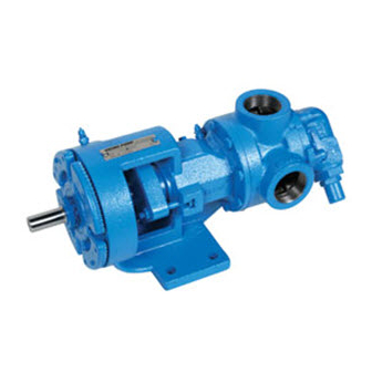
FIGURE 1:
H, HL SIZES
(H124E SHOWN)
LIQUID SPECIFIC PRODUCT LINE: CAST IRON
SIZES: H, HL, K, KK, L, LQ, LL, LS, Q, QS, N
...............................................16
FIGURE 2: K, KK,
L, LQ, LL, LS SIZES
(LS124E SHOWN)
© 2019 Viking Pump, Inc. • Cedar Falls, IA
Key Layout & Functions .......................................................20
Operation ..............................................................................21
Troubleshooting ....................................................................21
Technical Data - Controller ...................................................22
Technical Data - Relay .........................................................22
Dismantling & Disposal ........................................................23
......................................................23
General Installation Notes ........................................................23
Foundation ...............................................................................25
Component & Unit Lifting Features .........................................25
Alignment .................................................................................26
Piping .......................................................................................27
Start Up ....................................................................................28
Troubleshooting .......................................................................28
Vacuum Gauge - Suction Port .............................................28
Pressure Gauge - Discharge Port ........................................29
Rapid Wear .............................................................................30
Preventative Maintenance .......................................................30
Do's & Don'ts ...........................................................................31
Installation ............................................................................31
Operation ..............................................................................31
Maintenance .........................................................................31
MODEL NUMBER CHART
Packed
H124E
HL124E
K124E
KK124E
L124E
LQ124E
LL124E
LS124E
Q124E
QS124E
N324E
FIGURE 3:
Q, QS SIZES
(Q124E SHOWN)
TSM
1465
Page
1 of 32
Issue
A
FIGURE 4:
N SIZE
(N324E SHOWN)
Advertisement
Table of Contents
Troubleshooting

Related Manuals for Viking pump 124E Series


Summary of Contents for Viking pump 124E Series
-
Page 1: Table Of Contents
FIGURE 1: FIGURE 2: K, KK, FIGURE 3: FIGURE 4: H, HL SIZES L, LQ, LL, LS SIZES Q, QS SIZES N SIZE (H124E SHOWN) (LS124E SHOWN) (Q124E SHOWN) (N324E SHOWN) © 2019 Viking Pump, Inc. • Cedar Falls, IA... -
Page 2: Safety Information & Instructions
BEFORE operating the pump, be sure that: information, refer to Appendix, General Installation Notes, • It is clean and free from debris. item 5 on Pressure Protection or contact your Viking Pump ® representative for Engineering Service Bulletin ESB-31. • All valves in the suction and discharge pipelines are fully opened. -
Page 3: Controller Safety Information & Instructions
Failure to do so may result in damage to equipment and property, and/or injury or death. TSM 1465 | Issue A | Page 3 of 32 © 2019 Viking Pump, Inc. • Cedar Falls, IA... -
Page 4: Introduction
30 days to circulate the oil. Tighten all pump assembly bolts before putting pump in service after being stored. Relief Valve Adjusting Screw Cap TSM 1465 | Issue A | Page 4 of 32 © 2019 Viking Pump, Inc. • Cedar Falls, IA... -
Page 5: Suggested Repair Tools
Source: #472 J. H. Williams & Co. or equal; LS-QS pumps Contact your Authorized Viking Pump stocking distributor for available seal and rebuild kits ® FIGURE 6: EXPLODED VIEW (H, HL, K, KK, L, LQ, LL, LS SIZES) — 124E SERIES™ NOTE: IMAGE IS REPRESENTATIVE ONLY Item Name Of Part... - Page 6 Contact your Authorized Viking Pump stocking distributor for available seal and rebuild kits ® FIGURE 7: EXPLODED VIEW (Q, QS SIZES) — 124E SERIES™ NOTE: IMAGE IS REPRESENTATIVE ONLY Item Name Of Part Item Name Of Part Item Name Of Part...
- Page 7 Heater Cartridges for Casing Packing Idler and Bushing Assembly Heater Cartridges for Head Packing Retainer Washer Idler Bushing Bracket Bushing Idler Pin TSM 1465 | Issue A | Page 7 of 32 © 2019 Viking Pump, Inc. • Cedar Falls, IA...
-
Page 8: Removal: Packing
This will eliminate having to lift head into position K, KK, L, LQ, LL, LS when reassembling pump. Q, QS, N TSM 1465 | Issue A | Page 8 of 32 © 2019 Viking Pump, Inc. • Cedar Falls, IA... - Page 9 END CAP mounted on bracket. LIP SEALS 9. Inspect bracket bushing for wear and remove if damaged HALF ROUND RINGS or worn. TSM 1465 | Issue A | Page 9 of 32 © 2019 Viking Pump, Inc. • Cedar Falls, IA...
-
Page 10: Pump Assembly
Q, QS, N 170-190 on page 10 for lip orientation). 12. Adjust pump end clearance, refer to "Thrust Bearing Adjustment" on page 11. TSM 1465 | Issue A | Page 10 of 32 © 2019 Viking Pump, Inc. • Cedar Falls, IA... -
Page 11: Thrust Bearing Adjustment
4. Tighten setscrews in the outer face of the bearing housing. 5. Rotate the rotor shaft by hand to make sure it turns freely. TSM 1465 | Issue A | Page 11 of 32 © 2019 Viking Pump, Inc. • Cedar Falls, IA... -
Page 12: Pressure Relief Valve Instructions
Failure to follow above listed precautionary measures may result in serious injury or death. TSM 1465 | Issue A | Page 12 of 32 © 2019 Viking Pump, Inc. • Cedar Falls, IA... -
Page 13: Installation: Heat Cartridges
• Failure to follow these instructions may cause an electrical shock and/or sparks, which may result in serious injury or death. TSM 1465 | Issue A | Page 13 of 32 © 2019 Viking Pump, Inc. • Cedar Falls, IA... - Page 14 * The thermocouple location for the LS size is located on the opposite side of the bracket as shown in the drawing. FIGURE 15: HEAT CARTRIDGE & THERMOCOUPLE LOCATIONS (SIZES N) Thermocouple Heat Cartridges TSM 1465 | Issue A | Page 14 of 32 © 2019 Viking Pump, Inc. • Cedar Falls, IA...
-
Page 15: Single Channel Controller
For additional information on the heat cartridges, refer to "Installation: Heat Cartridges" on page 13. FIGURE 16: CONTROLLER PANEL LAYOUT Panel Bezel Mounting Collar Gasket Case TSM 1465 | Issue A | Page 15 of 32 © 2019 Viking Pump, Inc. • Cedar Falls, IA... -
Page 16: Dimensions: Relay (N Size Only)
0.630 in. (16 mm) or less, and the distance from the front of the bottom half and the panel is 0.525 in. (13.3 mm) or less. TSM 1465 | Issue A | Page 16 of 32 © 2019 Viking Pump, Inc. • Cedar Falls, IA... -
Page 17: Removing The Mounted Controller From Its Case
Verify orientation again if it will not slide back into the case 2. Using your thumbs push on either side of the controller until both latches click. TSM 1465 | Issue A | Page 17 of 32 © 2019 Viking Pump, Inc. • Cedar Falls, IA... -
Page 18: Wiring
3. Failure to follow this guideline could result in personal injury or death. Fuse NOT READY LIGHT Fuse Heat Cartridges READY LIGHT Controller Thermocouple* TSM 1465 | Issue A | Page 18 of 32 © 2019 Viking Pump, Inc. • Cedar Falls, IA... - Page 19 Power Input; AC; Fused (From Power Source) Common Not Used Heater Heater DC Input DC Input 9 - 16 Not Used TSM 1465 | Issue A | Page 19 of 32 © 2019 Viking Pump, Inc. • Cedar Falls, IA...
-
Page 20: Notes
Home Page. From the Home from a qualified heat control vendor. Page, you can clear alarms and errors if clearable. TSM 1465 | Issue A | Page 20 of 32 © 2019 Viking Pump, Inc. • Cedar Falls, IA... -
Page 21: Operation
The customer supplied fuse between the heat cartridges and controller will typically blow when one of the heat cartridges fails TSM 1465 | Issue A | Page 21 of 32 © 2019 Viking Pump, Inc. • Cedar Falls, IA... -
Page 22: Technical Data - Controller
Pollution Degree 2 Classification Power Control; Installation III Agency Approvals • UL 508 Listed and C-UL , File E73741 ® ® TSM 1465 | Issue A | Page 22 of 32 © 2019 Viking Pump, Inc. • Cedar Falls, IA... -
Page 23: Eu (European Union) Specifications
Per 2002/96/EC W.E.E.E. Directive, please recycle properly. FIGURE A2 The controller contains a lithium battery that must be recycled properly Left-Hand Right-Hand Pump Pump TSM 1465 | Issue A | Page 23 of 32 © 2019 Viking Pump, Inc. • Cedar Falls, IA... - Page 24 (e). When the force exerted by the liquid under the poppet exceeds that exerted by the spring, the poppet lifts and liquid starts to flow through the valve. TSM 1465 | Issue A | Page 24 of 32 © 2019 Viking Pump, Inc. • Cedar Falls, IA...
-
Page 25: Foundation
The slings can slide, allowing the unit to tip and/or fall. Improper lifts can result in personal injury and/or damage to the unit. TSM 1465 | Issue A | Page 25 of 32 © 2019 Viking Pump, Inc. • Cedar Falls, IA... -
Page 26: Alignment
Straightedge FIGURE A12: REDUCER DRIVE When sheaves are properly aligned, all points A, B, C, D will touch string or straightedge. TSM 1465 | Issue A | Page 26 of 32 © 2019 Viking Pump, Inc. • Cedar Falls, IA... -
Page 27: Piping
Keep Long Horizontal “Springing” or “drawing” the piping up to the pump will Line Below Liquid Level TSM 1465 | Issue A | Page 27 of 32 © 2019 Viking Pump, Inc. • Cedar Falls, IA... -
Page 28: Start Up
Liquid is too viscous to flow through the piping. 11. Do not use the Viking pump to flush, pressure test or c. Lift is too high. prove the system with water. Either remove the pump or d. -
Page 29: Pressure Gauge - Discharge Port
See Rapid Wear Table. 4. Pump is worn out. TSM 1465 | Issue A | Page 29 of 32 © 2019 Viking Pump, Inc. • Cedar Falls, IA... -
Page 30: Rapid Wear
TSM 1465 | Issue A | Page 30 of 32 © 2019 Viking Pump, Inc. • Cedar Falls, IA... -
Page 31: Do's & Don'ts
Operation under either of these conditions may result in a heat build-up in the pump, which could cause hazardous conditions or happenings. TSM 1465 | Issue A | Page 31 of 32 © 2019 Viking Pump, Inc. • Cedar Falls, IA... -
Page 32: 124E Series™, 324E Series™, Controller
Viking’s website (www.vikingpump.com/warranty/warranty-info). A complete copy of the warranty may also be obtained by contacting Viking through regular mail at Viking Pump, Inc., 406 State Street, Cedar Falls, Iowa 50613, USA. THIS WARRANTY IS AND SHALL BE VIKING’S SOLE...
Need help?
Do you have a question about the 124E Series and is the answer not in the manual?
Questions and answers