Table of Contents
Advertisement
VISIT VIKINGPUMP.COM FOR PDF OF CURRENT TSM ISSUE & TO VIEW REPAIR VIDEOS
TECHNICAL SERVICE MANUAL: INSTALLATION, OPERATION & MAINTENANCE
SIZES: G, GG, H, HJ, HL, AS, AK, AL, KE, KKE, LQE, LSE, Q, QS
TABLE OF CONTENTS
Model Number Chart ..................................................................1
Introduction ................................................................................1
Safety Information & Instructions ...............................................2
Special Information ....................................................................3
Rotation ..................................................................................3
Pressure Relief Valves ...........................................................3
Mechanical Seals ...................................................................3
Maintenance ...............................................................................3
Cleaning Pump .......................................................................3
Storage ...................................................................................3
Suggested Repair Tools .........................................................3
Pump Disassembly ....................................................................7
Pump Assembly .........................................................................8
Installation: Carbon Graphite Bushings ...................................10
Thrust Bearing Adjustment ......................................................10
Pressure Relief Valve Instructions ...........................................10
Disassembly ......................................................................... 11
Assembly .............................................................................. 11
Pressure Adjustment ............................................................ 11
Important .............................................................................. 11
...................................................... 11
General Installation Notes ........................................................ 11
Foundation ...............................................................................13
Component & Unit Lifting Features .........................................13
Alignment .................................................................................14
Piping .......................................................................................15
Start Up ....................................................................................16
Troubleshooting .......................................................................16
Vacuum Gauge - Suction Port .............................................16
Pressure Gauge - Discharge Port ........................................17
Rapid Wear .............................................................................18
Preventative Maintenance .......................................................18
Do's & Don'ts ...........................................................................19
Installation ............................................................................19
Operation ..............................................................................19
Maintenance .........................................................................19
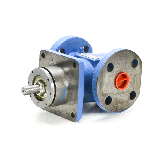
FIGURE 3: KE, KKE SIZES (4195 SERIES™)
MOTOR SPEED PRODUCT LINE: CAST IRON
495 SERIES™, 4195 SERIES™
© 2019 Viking Pump, Inc. • Cedar Falls, IA
MODEL NUMBER CHART
FLANGE
FOOT
MOUNTED
MOUNTED
G495
G4195
GG495
GG4195
H495
H4195
HJ495
HJ4195
HL495
HL4195
AS495
AS4195
AK495
AK4195
AL495
AL4195
Q4195
QS4195
INTRODUCTION
The illustrations used in this manual are for identification
purposes only and cannot be used for ordering parts.
Obtain a parts list from your Viking Pump
Always give a complete name of part, part number and
material with the model number and serial number of pump
when ordering repair parts. The unmounted pump or pump
unit model number and serial number are on the nameplate.
This manual only applies to the pump models specified in the
"Model Number Chart" on page 1. Pump specifications and
recommendations are listed in the Catalog Sections, which
are available at vikingpump.com.
FIGURE 1:
G, GG, H, HJ, HL SIZES
(495 SERIES™)
FIGURE 4: Q, QS SIZES (4195 SERIES™)
TSM
1441
Page
1 of 20
Issue
A
FLANGE & FOOT
MOUNTED
KE4195
KKE4195
LQE4195
LSE4195
representative.
®
FIGURE 2:
AS, AK, AL SIZES
(4195 SERIES™)
Advertisement
Table of Contents


Need help?
Do you have a question about the 495 Series and is the answer not in the manual?
Questions and answers