Advertisement
Table of Contents
Electronic copies of the most current TSM issue can be found on the Viking Pump website at www.vikingpump.com
CONTENTS
Safety Information & Instructions . . . . . . . . . . . . 2
Special Information . . . . . . . . . . . . . . . . . . . 3
Maintenance . . . . . . . . . . . . . . . . . . . . . . 3
Disassembly . . . . . . . . . . . . . . . . . . . . . . 4
Assembly . . . . . . . . . . . . . . . . . . . . . . . . 5
Thrust Bearing Adjustment . . . . . . . . . . . . . . . 6
Installation of Carbon Graphite Bushings . . . . . . . . 6
Pressure Relief Valve Instructions . . . . . . . . . . . 7
INTRODUCTION
The illustrations used in this manual are for identification
purposes only and cannot be used for ordering parts. Obtain
a parts list from the factory or a Viking representative. Always
give a complete name of part, part number and material with
the model number and serial number of pump when ordering
repair parts. The unmounted pump or pump unit model
number and serial number are on the nameplate.
In the Viking model number system, basic size letters are
combined with series number (4124B, 4224B) indicating
basic pump construction material.
This manual deals only with Series 4124B (non-jacketed)
and 4224B (jacketed) Heavy Duty Bracket Mounted Pumps.
Refer to Figures 1 through 7 for general configuration and
nomenclature used in this manual. Pump specifications
and recommendations are listed in Catalog Section 628,
Viking Behind the Rotor Seal Internal Gear Pumps.
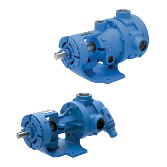
FIGURE 1 - K4124B
VIKING PUMP, INC.
TECHNICAL SERVICE MANUAL
BEHIND THE ROTOR SEAL HEAVY DUTY PUMPS
SERIES 4124B AND 4224B CAST IRON
SIZES G, H, HL, AK, K, KK, L, LQ, LL
•
A Unit of IDEX Corporation
UNMOUNTED PUMP
B = Bracket Mounted Pump
G4124B
with Mechanical Seal
H4124B
H4224B
Behind the Rotor
HL4124B
HL4224B
Units are designated by the unmounted
AK4124B
pump model numbers followed by a
K4124B
K4224B
letter indicating drive style.
KK4124B
KK4224B
V = V-Belt
L4124B
L4224B
D = Direct Connected
LQ4124B
LQ4224B
R = Viking Speed Reducer
LL4124B
LL4224B
P = Commercial Speed Reducer
Note: Series 4124B and 4224B pumps fitted with optional
pinned-seat seals (the abrasive liquid seals used in 4624B
Series pumps) should reference Technical Service Manual
410.4 for information on seal replacement.
FIGURE 2 - L4224B
•
Cedar Falls, IA 50613 USA
SECTION
TSM 628
PAGE
1 OF 8
ISSUE
A
UNITS
Advertisement
Table of Contents

Subscribe to Our Youtube Channel
Related Manuals for Viking pump G4124B


Summary of Contents for Viking pump G4124B
- Page 1 Electronic copies of the most current TSM issue can be found on the Viking Pump website at www.vikingpump.com TECHNICAL SERVICE MANUAL SECTION TSM 628 BEHIND THE ROTOR SEAL HEAVY DUTY PUMPS PAGE 1 OF 8 SERIES 4124B AND 4224B CAST IRON...
-
Page 2: Safety Information & Instructions
● You know what material the pump has been For weight of the pump alone (which does not include handling, have obtained a material safety data the drive and/or base plate) refer to the Viking Pump sheet (MSDS) for the material, and understand product catalog. -
Page 3: Special Information
Series 4124B & 4224B pumps are designed for long, trouble- DANGER ! free service life under a wide variety of application conditions with a minimum of maintenance. The points listed below will Before opening any Viking pump liquid chamber help provide long service life. (pumping chamber,... -
Page 4: Disassembly
DANGER ! port connections to allow for proper flow of liquid through the pump. Before opening any Viking pump liquid chamber Remove head from pump. Do not allow idler to fall from (pumping chamber,... -
Page 5: Assembly
BALL BEARING Clean rotor shaft and seal housing bore. Make sure they BEARING HOUSING are free of dirt, grit and scratches. Gently radius leading edge of shaft diameter over which seal is to be placed. SETSCREW Never touch mechanical seal faces with anything except clean hands or clean cloth. -
Page 6: Thrust Bearing Adjustment
Note: G size has no lip seal. on the viscosity of the liquid pumped. For specific recommendations, consult your Viking Pump distributor. 15. Put lockwasher and locknut on shaft. Insert length of hardwood or brass through port opening between rotor teeth to keep shaft from turning. -
Page 7: Pressure Relief Valve Instructions
PRESSURE RELIEF VALVE DISASSEMBLY INSTRUCTIONS DANGER ! Before opening any Viking pump liquid chamber (pumping chamber, reservoir, relief valve adjusting cap fitting, etc.) Be sure: 1. That any pressure in the chamber has been completely vented through the suction or discharge lines or other appropriate openings or connections. -
Page 8: Section Tsm
(www.vikingpump.com/warranty/warranty-info). A complete IMPORTANT copy of the warranty may also be obtained by contacting Viking through regular mail at Viking Pump, Inc., 406 State In ordering parts for pressure relief valve, always give Street, Cedar Falls, Iowa 50613, USA. model number and serial number of pump as it appears on THIS WARRANTY IS AND SHALL BE VIKING’S SOLE...
Need help?
Do you have a question about the G4124B and is the answer not in the manual?
Questions and answers