Page 1
CONSUMER SERVICES TECHNICAL R-103 EDUCATION GROUP PRESENTS DEHUMIDIFIERS Models: AD25BSS, AD35DSS, AD50DSS Models: AD35USS, AD50USS, AD70USS JOB AID Part No. 8178563...
Page 2
FORWARD This Whirlpool Job Aid, “Dehumidifier” (Part No. 8178563), provides the technician with informa- tion on the operation and service of the Dehumidifier. For specific information on the model being serviced, refer to the “Use and Care Guide,” or “Wiring Diagram” provided with the dehumidifier.
GENERAL DEHUMIDIFIER SAFETY Your safety and the safety of others are very important. We have provided many important safety messages in this Manual and on your appliance. Always read and obey all safety messages. This is the safety alert symbol. This symbol alerts you to potential hazards that can kill or hurt you and others.
MODEL & SERIAL NUMBER DESIGNATIONS MODEL NUMBER AD 50 U S MODEL NUMBER PRODUCT GROUP AD = Dehumidifier, Whirlpool RD = Dehumidifier, Roper CAPACITY (24 HR.) 25 Pints 35 Pints 50 Pints 70 Pints MODEL FEATURES B = Electromechanical, No Deicer, 1 Speed Fan C = Electromechanical, Std.
MODEL & SERIAL NUMBER AND WIRING DIAGRAM LABEL LOCATIONS Model & Serial Number Label (Behind Water Bucket) Wiring Diagram Label (Inside Front Half Of Cabinet)
PRODUCT OPERATION THEORY OF OPERATION WHAT IS HUMIDITY? REMOVING UNWANTED HUMIDITY Humidity is defined as the amount of water va- A dehumidifier is designed to remove unwanted por in the air and is measured as a percentage moisture from the air and maintain relative of the amount of water vapor the air can hold humidity at acceptable levels.
Page 10
OPERATING CHARACTERISTICS LOW TEMPERATURE OPERATION When a dehumidifier begins its run cycle, a Mechanical control models without a deicer thermostat, i.e. AD25BSS, must not be oper- partial frosting of the evaporator can be ob- ated below 65°F. Mechanical control models served.
Page 11
FAN SPEED: Controls the fan operation, as on. If the relative humidity has not increased, follows: the unit will only run for 3 minutes. There is a 3 minute minimum “on” or “off” time used to High: For faster moisture removal protect the compressor that requires at least Low: For slower moisture removal 3 minutes of run time or off time before the...
DEHUMIDIFIER USE SETTING THE CONTROLS (CONTROL TYPES 1 & 2 ONLY) Starting/Stopping the Dehumidifier NOTE: Before turning on the dehumidifier, be sure that the bucket is empty and fits all the way into the dehumidifier. Control Type 1 Electrical Shock Hazard NOTE: Minimum operating temperature is Plug into a grounded 3 prong outlet.
Dryness Control The Dryness Control regulates the amount of moisture in the room. Turn the control knob clockwise for more drying. Turn the control knob counterclockwise for less drying. Turn the control knob to “Dry” to maintain average humidity conditions. Electrical Shock Hazard NOTE: For the first few days of use, turn the DRYNESS CONTROL clockwise to CONTINU-...
DRAINING THE DEHUMIDIFIER • Auto —Will provide the maximum humid- ity control by automatically adjusting the fan speed and/or turning the dehumidifier on and off to maintain humidity setting. Sickness Hazard Desired Humidity (Control Type 3 Models Only) Do not drink water collected in water bucket.
3. Pour water through opening into a sink or 3. Attach a garden hose to drain hose connec- tub. tor on the inside of the dehumidifier. Hand tighten. A. Garden hose B. Drain hose connector 4. Place the other end of garden hose into a 4.
DEHUMIDIFIER CARE CLEANING THE AIR FILTER CLEANING THE DEHUMIDIFIER (ON SOME MODELS) Exterior The air filter is removable for easy cleaning. A NOTE: Have an authorized service technician clean filter helps remove dust, lint, and other clean and service the interior coils of your particles from the air and is important for best product annually.
COMPONENT ACCESS This section instructs you on how to service the Dehumidifier. The components and their loca- tions are shown below. NOTE: The sealed system in the Dehumidifier is not serviced. COMPONENT LOCATIONS Electrical Shock Hazard Disconnect power before servicing. Replace all parts and panels before operating.
REMOVING THE CABINET If present, pull the air filter down and out from behind the front louvers. Remove the two front screws from the front half of the cabinet. Electrical Shock Hazard Disconnect power before servicing. Replace all parts and panels before operating.
Page 19
Remove the bottom screw and the two Pull the front and rear halves of the cabi- top hex-head screws from the rear half of net from the dehumidifier and remove the cabinet. them. Top Rear Screws Rear Half Front Half Bottom Rear Screw...
REMOVING THE ELECTRONIC CONTROL, THERMISTOR, AND POWER SUPPLY CORD Disconnect the four wire connectors from the electronic control. Electronic Control Electrical Shock Hazard Disconnect power before servicing. Replace all parts and panels before operating. Failure to do so can result in death or electrical shock.
Page 21
Unclip the thermistor from the tubing and Remove the power supply cord from the remove it. NOTE: Do not remove the cabinet. thermistor from the clip. Remove the hex-head screw from the green ground wire. Power Supply Cord Thermistor & Clip 10.
REMOVING THE MECHANICAL HUMIDISTAT, LIGHT, AND POWER SUPPLY CORD Unsnap the four top cover tabs from the mechanical control and remove the cover. Electrical Shock Hazard Top Cover Tabs Disconnect power before servicing. Replace all parts and panels before operating. Failure to do so can result in death or electrical shock.
Page 23
To remove the power supply cord: c) Remove the hex-head screw from the green ground wire at the top of the a) Disconnect the white power supply condenser. cord wire from the compressor capaci- tor terminal. b) Disconnect the black power supply cord wire from the COM terminal of the bucket switch.
REMOVING THE FAN CAPACITOR AND THE FAN MOTOR To remove the fan motor: a) Loosen the T-20 Torx screw and pull the blower off the fan motor shaft. Brown Wires Electrical Shock Hazard Capacitor Screw Disconnect power before servicing. Replace all parts and panels before operating.
Page 25
• Top green ground wire on condenser. c) Remove the three 5/16˝ hex-head screws from the fan motor, then pull the wiring out of the access hole and remove the motor. Top Ground Wire Screw Condenser Fan Motor Screws...
REMOVING THE COMPRESSOR CAPACITOR AND THE BUCKET SWITCH To remove the compressor capacitor: a) IMPORTANT: Discharge the capacitor by touching the leads of a 20,000 ohm resistor to the capacitor terminals. b) Disconnect the three wires (electronic control models), or four wires (me- chanical models) from the capacitor Electrical Shock Hazard terminals.
Page 27
To remove the bucket switch: c) Press the locking tab, push the switch holder through the cutout, and remove Electronic Model: it from the dehumidifier. a) Disconnect the two black wires from the N.C. and COM switch terminals. Mechanical Models: b) Disconnect the black (COM), tan (N.O.), and yellow (N.C.) wires from the switch terminals.
COMPONENT TESTING Before testing any of the components, per- • Check all connections before replacing form the following checks: components, looking for broken or loose wires, failed terminals, or wires not pressed • The most common cause for control failure into connectors far enough.
Electrical Shock Hazard Disconnect power before servicing. Replace all parts and panels before operating. Failure to do so can result in death or electrical shock. FAN MOTOR BUCKET SWITCH Actuator N.C. N.O. Refer to page 3-8 for the procedure for ac- Refer to page 3-10 for the procedure for ac- cessing the fan motor.
DIAGNOSTICS & TROUBLESHOOTING DIAGNOSTICS 1. Turn off the dehumidifier with the power • If you press a wrong key during the 3-key button. sequence, or if more than 5 seconds elap- ses before completing the sequence, you 2. Remove the bucket. will need to restart the sequence from the 3.
TROUBLESHOOTING Electrical Shock Hazard Disconnect power before servicing. Replace all parts and panels before operating. Failure to do so can result in death or electrical shock. PROBLEM CAUSE CORRECTION 1. Unit not turned “ON” or not set dry 1. Set control to “CONTINUOUS.” This will allow the fan and com- enough.
PRODUCT SPECIFICATIONS WARRANTY INFORMATION SOURCES IN THE UNITED STATES: FOR PRODUCT SPECIFICATIONS AND WARANTY INFORMATION CALL: FOR WHIRLPOOL PRODUCTS: 1-800-253-1301 FOR KITCHENAID PRODUCTS: 1-800-422-1230 FOR ROPER PRODUCTS: 1-800-447-6737 FOR TECHNICAL ASSISTANCE WHILE AT THE CUSTOMER’S HOME CALL: THE TECHNICAL ASSISTANCE LINE: 1-800-253-2870...
Need help?
Do you have a question about the AD70USS and is the answer not in the manual?
Questions and answers
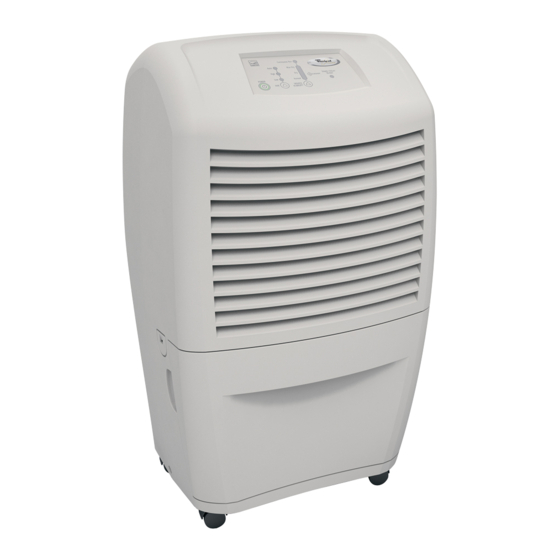
What should be desired humidity setting for this dehumidifier
The recommended humidity setting for the Whirlpool dehumidifier AD70USS is the "normal" setting to maintain average humidity conditions.
This answer is automatically generated