
Related Manuals for Whirlpool AD50USS


Summarization of Contents
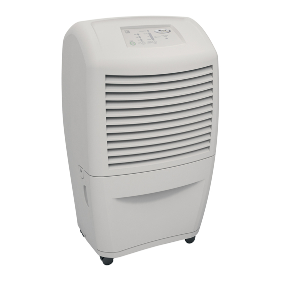
GENERAL
DEHUMIDIFIER SAFETY
Explains safety alert symbols, DANGER and WARNING messages for hazard identification and risk reduction.
MODEL & SERIAL NUMBER DESIGNATIONS
Describes the structure and meaning of model and serial numbers for identification and tracking purposes.
MODEL & SERIAL NUMBER AND WIRING DIAGRAM LABEL LOCATIONS
Shows the specific locations on the dehumidifier where model and serial number labels are affixed.
PRODUCT OPERATION
THEORY OF OPERATION
Explains how dehumidifiers remove moisture using a refrigeration cycle, including evaporator and condenser functions.
OPERATING CHARACTERISTICS
Details frosting behavior, performance in cold conditions, and temperature limitations for optimal operation.
TYPICAL OPERATION OVERVIEW
Explains control panel functions, indicator lights, and user adjustments for moisture removal.
LOW TEMPERATURE OPERATION GUIDELINES
Specific operating parameters and limitations for different models when used in low ambient temperatures.
ELECTRONIC CONTROL SENSORS EXPLAINED
Describes the function and role of the humidistat and thermistor in electronic control models.
DEFECTIVE ELECTRONIC SENSOR BEHAVIOR
Outlines the default operational behavior of electronic models when sensors fail.
FAN SPEED CONTROL FUNCTIONS
Explains how fan speed settings affect moisture removal rate and noise level.
DRYNESS CONTROL ADJUSTMENT
Details how to set the dryness control to achieve the desired level of dehumidification.
ADJUST/EMPTY BUCKET LIGHT INDICATOR
Explains the purpose and conditions for the 'Adjust/Empty Bucket' light indicator.
DEHUMIDIFIER USE
SETTING CONTROLS FOR TYPES 1 & 2
Guides on starting, stopping, and setting controls for dehumidifier models with control types 1 and 2.
DRYNESS CONTROL FUNCTIONALITY DETAILS
Further explanation of dryness control settings, including continuous run for extra moisture removal.
SETTING CONTROLS FOR TYPE 3 MODELS
Guides on starting, stopping, and setting controls for dehumidifier models with control type 3.
EMPTY/ADJUST BUCKET LIGHT FUNCTIONALITY
Explains the light indicator for bucket status and correct installation for unit operation.
FAN SPEED SELECTION FOR TYPE 3 MODELS
How to select fan speed options (Low, High, Auto) on Type 3 control models.
DESIRED HUMIDITY SETTINGS FOR TYPE 3 MODELS
How to select desired humidity levels (Normal, Dry, Max Dry, Continuous Run) on Type 3 models.
DRAINING THE DEHUMIDIFIER METHODS
Overview of how to drain collected water from the dehumidifier using different options.
DRAINING VIA BUCKET REMOVAL PROCEDURE
Step-by-step instructions to drain water by removing and emptying the internal collection bucket.
DRAINING VIA CONNECTED DRAIN HOSE PROCEDURE
Step-by-step instructions to drain water using a connected garden hose to a floor drain.
DEHUMIDIFIER CARE
CLEANING THE AIR FILTER GUIDE
Instructions for cleaning or washing the removable air filter to maintain operating efficiency.
CLEANING THE DEHUMIDIFIER EXTERIOR
How to clean the outside surfaces of the dehumidifier using a soft brush or vacuum attachment.
COMPONENT ACCESS
COMPONENT LOCATIONS OVERVIEW
Visual guide showing the placement of key internal components within the dehumidifier.
REMOVING THE CABINET PROCEDURE
Step-by-step instructions for disassembling the unit's outer casing to access internal parts.
REMOVING ELECTRONIC CONTROL, THERMISTOR, AND POWER CORD
Procedure to remove specific electronic components including control board, thermistor, and power cord.
REMOVING MECHANICAL HUMIDISTAT, LIGHT, AND POWER CORD
Procedure to remove mechanical controls, indicator light, and power supply cord.
REMOVING FAN CAPACITOR AND FAN MOTOR
Instructions for accessing and removing the fan motor and its associated capacitor.
REMOVING COMPRESSOR CAPACITOR AND BUCKET SWITCH
Procedure to remove the compressor capacitor and the bucket switch assembly.
COMPONENT TESTING
MECHANICAL HUMIDISTAT TESTING PROCEDURE
Steps to test the mechanical humidistat's continuity using an ohmmeter.
CAPACITOR TESTING PROCEDURE (FAN & COMPRESSOR)
How to test fan and compressor capacitors for proper resistance and discharge.
FAN MOTOR TESTING PROCEDURE
Steps to test the fan motor's resistance across different wire leads.
BUCKET SWITCH TESTING PROCEDURE
How to test the bucket switch's continuity in both open and closed states.
DIAGNOSTICS & TROUBLESHOOTING
RUNNING DIAGNOSTIC TESTS
Instructions to enter diagnostic mode using specific button press sequences to check component status.
TROUBLESHOOTING COMMON PROBLEMS
A guide to identify and resolve common dehumidifier issues based on symptoms, causes, and corrections.
WIRING DIAGRAMS
WIRING DIAGRAM 1 SCHEMATIC
Electrical schematic illustrating the wiring for one configuration of the dehumidifier.
WIRING DIAGRAM 2 SCHEMATIC
Electrical schematic illustrating the wiring for a second configuration of the dehumidifier.
WIRING DIAGRAM 3 SCHEMATIC
Electrical schematic illustrating the wiring for a third configuration of the dehumidifier.
Need help?
Do you have a question about the AD50USS and is the answer not in the manual?
Questions and answers