Table of Contents
Advertisement
Quick Links
Advertisement
Table of Contents

Related Manuals for Asus RAMPAGE III BLACK EDITION


Summary of Contents for Asus RAMPAGE III BLACK EDITION
- Page 1 Rampage III Black Edition...
- Page 2 Product warranty or service will not be extended if: (1) the product is repaired, modified or altered, unless such repair, modification of alteration is authorized in writing by ASUS; or (2) the serial number of the product is defaced or missing.
-
Page 3: Table Of Contents
Contents Notices ......................ix Safety information ..................xiii About this guide ..................xv Rampage III Black Edition specifications summary ......xvii Chapter 1: Product introduction Welcome! ..................1-1 Package contents ................. 1-1 Special features ................1-2 1.3.1 Product highlights ............1-2 1.3.2... - Page 4 BIOS Setup Managing and updating your BIOS ..........3-1 3.1.1 ASUS Update utility ............3-1 3.1.2 ASUS EZ Flash 2 utility ........... 3-5 3.1.3 ASUS CrashFree BIOS 3 utility ........3-6 BIOS Setup program ..............3-7 3.2.1 BIOS menu screen ............3-8 3.2.2...
- Page 5 IOH PCIE Voltage [Auto] ..........3-15 3.3.38 ICH Voltage [Auto] ............3-15 3.3.39 ICH PCIE Voltage [Auto] ..........3-15 3.3.40 ASUS O.C. Profile ............3-15 3.3.41 CPU Spread Spectrum [Auto] ........3-16 3.3.42 PCIE Spread Spectrum [Auto] ........3-16 Main menu .................. 3-17 3.4.1...
- Page 6 Boot Device Priority ............3-40 3.7.2 Boot Settings Configuration .......... 3-41 3.7.3 Security ................. 3-42 Tools menu ................. 3-44 3.8.1 ASUS EZ Flash 2 ............3-44 3.8.2 ASUS O.C. Profile ............3-45 3.8.3 GO Button File .............. 3-47 3.8.4 BIOS FlashBack ............3-48...
- Page 7 Contents Chapter 4: Software support Installing an operating system ........... 4-1 Support DVD information ............4-1 4.2.1 Running the support DVD ..........4-1 4.2.2 Obtaining the software manuals ........4-2 Software information ..............4-3 4.3.1 AI Suite II ................ 4-3 4.3.2 DIGI+ VRM ..............
- Page 8 Contents 5.1.5 Enabling the ATI CrossFireX™ technology ....5-3 ® NVIDIA SLI™ technology ............5-5 ® 5.2.1 Requirements ..............5-5 5.2.2 Installing two SLI-ready graphics cards ......5-5 5.2.3 Installing the device drivers ..........5-6 5.2.4 Enabling the NVIDIA SLI™ technology ......5-6 ®...
-
Page 9: Notices
Notices Federal Communications Commission Statement This device complies with Part 15 of the FCC Rules. Operation is subject to the following two conditions: • This device may not cause harmful interference, and • This device must accept any interference received including interference that may cause undesired operation. - Page 10 RF exposure warning This equipment must be installed and operated in accordance with provided instructions and the antenna(s) used for this transmitter must be installed to provide a separation distance of at least 20 cm from all persons and must not be co-located or operating in conjunction with any other antenna or transmitter.
- Page 11 Wireless Operation Channel for Different Domains N. America 2.412-2.462 GHz Ch01 through CH11 Japan 2.412-2.484 GHz Ch01 through Ch14 Europe ETSI 2.412-2.472 GHz Ch01 through Ch13 France Restricted Wireless Frequency Bands Some areas of France have a restricted frequency band. The worst case maximum authorized power indoors are: •...
-
Page 12: Canadian Department Of Communications Statement
Canadian Department of Communications Statement This digital apparatus does not exceed the Class B limits for radio noise emissions from digital apparatus set out in the Radio Interference Regulations of the Canadian Department of Communications. This class B digital apparatus complies with Canadian ICES-003. Cet appareil numérique de la classe [B] est conforme à... -
Page 13: Safety Information
Safety information Electrical safety • To prevent electrical shock hazard, disconnect the power cable from the electrical outlet before relocating the system. • When adding or removing devices to or from the system, ensure that the power cables for the devices are unplugged before the signal cables are connected. If possible, disconnect all power cables from the existing system before you add a device. - Page 14 ASUS Recycling/Takeback Services ASUS recycling and takeback programs come from our commitment to the highest standards for protecting our environment. We believe in providing solutions for you to be able to responsibly recycle our products, batteries, other components as well as the packaging materials.
-
Page 15: About This Guide
Refer to the following sources for additional information and for product and software updates. ASUS websites The ASUS website provides updated information on ASUS hardware and software products. Refer to the ASUS contact information. Optional documentation Your product package may include optional documentation, such as warranty flyers, that may have been added by your dealer. -
Page 16: Conventions Used In This Guide
Conventions used in this guide To ensure that you perform certain tasks properly, take note of the following symbols used throughout this manual. DANGER/WARNING: Information to prevent injury to yourself when trying to complete a task. CAUTION: Information to prevent damage to the components when trying to complete a task. -
Page 17: Rampage Iii Black Edition Specifications Summary
Core™i7 Processor Extreme ® Edition / Core™i7 Processor Edition / Core™i7 Processor Support Intel Turbo Boost Technology ® * Refer to www.asus.com for Intel CPU support list Chipset Intel X58/ICH10R ® System Bus Up to 6.4 GT/s with QuickPath Interconnection... - Page 18 Rampage III Black Edition specifications summary ThunderBolt LAN/Audio Dedicated network processing unit (NPU) - Advanced Game Detect™ Advanced Game Detect™ Combo Card - Visual Bandwidth Control™ Visual Bandwidth Control™ - Application Blocking Application Blocking - Online Gaming PC Monitor™ Online Gaming PC Monitor™...
- Page 19 ASUS CrashFree BIOS 3 Q-Fan Plus ROG BIOS Wallpaper ASUS EPU Engine ASUS Q-Connector ASUS Q-LED (CPU, DRAM, VGA, Boot Device LED) ASUS Q-Slot ASUS Q-DIMM Back Panel I/O Ports 1 x PS/2 Keyboard port 2 x Wi-Fi antenna jacks...
- Page 20 Rampage III Black Edition specifications summary Internal I/O Connectors 1 x USB 3.0 connector supports additional 2 USB 3.0 ports ports 2 x USB 2.0 connectors support additional 4 USB 2.0 ports ports 8 x SATA connectors: 2 x SATA 6G connectors (Grey);...
-
Page 21: Chapter 1: Product Introduction
This chapter describes the motherboard features and the new technologies it supports. Chapter 1: Product introduction... - Page 22 Chapter summary Welcome! ..................1-1 Package contents ................. 1-1 Special features ................1-2 ROG Rampage III Black Edition...
-
Page 23: Welcome
Welcome! Thank you for buying an ROG Rampage III Black Edition motherboard! The motherboard delivers a host of new features and latest technologies, making it another standout in the long line of ASUS quality motherboards! Before you start installing the motherboard, and hardware devices on it, check the items in your package with the list below. -
Page 24: Special Features
Green ASUS This motherboard and its packaging comply with the European Union’s Restriction on the use of Hazardous Substances (RoHS). This is in line with the ASUS vision of creating environment-friendly and recyclable products/packaging to safeguard consumers’ health while minimizing the impact on the environment. -
Page 25: Rog Thunderbolt Lan/Audio Combo
With fine-tuned background sound effects for popular game types and Xear 3D Surround tech, ROG ThunderBolt lets you hear better and win easier! ROG Rampage III Black Edition... -
Page 26: Rog Intelligent Performance & Overclocking Features
Still overclock your PC the old-fashioned way? Let ROG iDirect bring you a whole new tweaking experience right on your iPhone or iPad! Thanks to the Bluetooth support that comes with select ASUS ROG motherboards, you can monitor your PC and tweak parameters such voltages and frequencies in real time wirelessly... - Page 27 This design allows advanced user control and management to be processed purely at a hardware level. iROG greatly increases fun during overclocking for PC enthusiasts and it offers system maintenance and management with more control and efficiency. ROG Rampage III Black Edition...
-
Page 28: Voltiminder Led
BIOS Flashback Two BIOS ROM. Two BIOS settings. Twice the overclocking flexibility. Overclocker's prayer to have BIOS flexibility is answered! With the new BIOS Flashback, PC enthusiasts can overclock with even more confidence. BIOS Flashback gives overclockers the ability to save two versions of the BIOS simultaneously. -
Page 29: Asus Special Features
With Q-Fan Plus, special temperature sensor cable is provided to detect temperature on any device. When used with optional fans, you may activate Q-Fan function on up to 3 additional devices of your choice! ROG Rampage III Black Edition... - Page 30 ASUS Q-Connector Make connections quick and accurate The Q-Connector allows you to connect or disconnect chassis front panel cables in one easy step with one complete module. This unique adapter eliminates the trouble of plugging in one cable at a time, making connection quick and accurate.
-
Page 31: Chapter 2: Hardware Information
This chapter lists the hardware setup procedures that you have to perform when installing system components. It includes description of the jumpers and Chapter 2: Hardware connectors on the motherboard. information... - Page 32 Chapter summary Before you proceed ..............2-1 Motherboard overview ..............2-2 Building your computer system ..........2-42 Starting up for the first time ............2-60 Turning off the computer ............2-61 ASUS Rampage III Black Edition...
-
Page 33: Before You Proceed
Before you install or remove any component, ensure that the ATX power supply is switched off or the power cord is detached from the power supply. Failure to do so may cause severe damage to the motherboard, peripherals, or components. ASUS Rampage III Black Edition... -
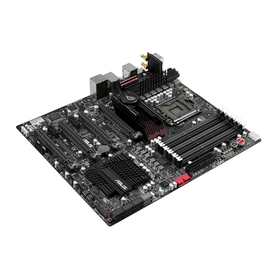
Page 34: Motherboard Overview
Motherboard overview 2.2.1 Motherboard layout Refer to 2.2.8 Connectors for more information about rear panel connectors and internal connectors. Chapter 2: Hardware information... -
Page 35: Layout Contents
USB 2.0 connectors (10-1 pin USB78; USB�10) 2-35 Clear RTC RAM (3-pin CLRTC�SW) 2-31 Digital audio connector (4-1 pin SPDIF�OUT) 2-36 Front panel audio connector (10-1 pin AAFP) 2-39 ROG Logo LED connector (3-pin ROG) 2-38 ASUS Rampage III Black Edition... -
Page 36: Central Processing Unit (Cpu)
ASUS will shoulder the cost of repair only if the damage is shipment/transit-related. • Keep the cap after installing the motherboard. ASUS will process Return Merchandise Authorization (RMA) requests only if the motherboard comes with the cap on the LGA1366 socket. -
Page 37: System Memory
The motherboard comes with six Double Data Rate 3 (DDR3) Dual Inline Memory Modules (DIMM) slots. A DDR3 module is notched differently from a DDR or DDR2 module. DO NOT install a DDR or DDR2 memory module to the DDR3 slot. ASUS Rampage III Black Edition... -
Page 38: Memory Configurations
Memory configurations You may install 1GB, 2GB and 4GB unbuffered and non-ECC DDR3 DIMMs into the DIMM sockets. • You may install varying memory sizes in Channel A, Channel B and Channel C. The system maps the total size of the lower-sized channel for the dual-channel or triple-channel configuration. - Page 39 Rampage III Black Edition Motherboard Qualified Vendors Lists (QVL) DDR�-24��MH�� capability 3-2400MHz capability -2400MHz capability Vendors Part No. Size SS/DS Timing Voltage DIMM socket support (Optional) 2 DIMM 3 DIMM 4 DIMM 6 DIMM G.SKILL F3-19200CL9D-4GBPIS(XMP) 4GB ( 2x 2G ) 9-11-11-31 1.65...
- Page 40 Rampage III Black Edition Motherboard Qualified Vendors Lists (QVL) DDR�-2���MH�� capability 3-2133MHz capability -2133MHz capability Vendors Part No. Size SS/DS Timing Voltage DIMM socket support (Optional) 2 DIMM 3 DIMM 4 DIMM 6 DIMM • • CORSAIR CMT4GX3M2A2133C9(XMP) 4GB ( 2x 2GB ) 9-10-9-24 1.65...
- Page 41 • • • • Team TXD32048M2000C9-L(XMP) 9-9-9-24 • Team TXD32048M2000C9-L(XMP) 9-9-9-24 Rampage III Black Edition Motherboard Qualified Vendors Lists (QVL) DDR�-����MH�� capability 3-1866MHz capability -1866MHz capability Vendors Part No. Size SS/DS Timing Voltage DIMM socket support (Optional) 2 DIMM 3 DIMM...
- Page 42 Rampage III Black Edition Motherboard Qualified Vendors Lists (QVL) DDR�-����MH�� capability 3-1600MHz capability -1600MHz capability Vendors Part No. Size SS/DS Timing Voltage DIMM socket support (Optional) 2 DIMM 3 DIMM 4 DIMM 6 DIMM • • • • A-DATA AX3U1600GC4G9-DG2(XMP)
- Page 43 • • • • • Patriot PVT36G1600LLK(XMP) 6GB(3 x 2GB) 8-8-8-24 1.65 • • • • Team TXD31024M1600C8-D(XMP) 8-8-8-24 1.65 • • Team TXD32048M1600C7-L(XMP) 7-7-7-24 1.65 Team TXD32048M1600HC8-D(XMP) 8-8-8-24 1.65 • • • • ASUS Rampage III Black Edition 2-11...
- Page 44 Rampage III Black Edition Motherboard Qualified Vendors Lists (QVL) DDR�-����MH�� capability 3-1333MHz capability -1333MHz capability Vendors Part No. Size SS/DS Timing Voltage DIMM socket support (Optional) 2 DIMM 3 DIMM 4 DIMM 6 DIMM • • • • Apacer 78.01GC6.9L0 Apacer 78.A1GC6.9L1...
- Page 45 • • • • BUFFALO D3U1333-4G EK Memory EKM324L28BP8-I13 4GB(2 x 2GB) • • • • • • • • Elixir M2F2G64CB88B7N-CG • • • • Elixir M2F4G64CB8HB5N-CG GoodRam GR1333D364L9/2G • • • • ASUS Rampage III Black Edition 2-13...
- Page 46 Team TXD32048M1333C7-D(XMP) 7-7-7-21 1.5-1.6 Team TXD32048M1333C7-D(XMP) 7-7-7-21 1.5-1.6 • • • • Rampage III Black Edition Motherboard Qualified Vendors Lists (QVL) DDR�-����MH�� capability 3-1067MHz capability -1067MHz capability Vendors Part No. Size SS/DS Timing Voltage DIMM socket support (Optional) 2 DIMM...
- Page 47 B1 and C1) and the gray slot A2 as one set of Triple-channel memory configuration. • 6 DIMMs: Supports six (6) modules inserted into both the gray slots and the black slots as two set of Triple-channel memory configuration. ASUS Rampage III Black Edition 2-15...
-
Page 48: Expansion Slots
2.2.5 Expansion slots In the future, you may need to install expansion cards. The following sub-sections describe the slots and the expansion cards that they support. Ensure to unplug the power cord before adding or removing expansion cards. Failure to do so may cause you physical injury and damage motherboard components. -
Page 49: Irq Assignments For This Motherboard
Onboard USB 3.0 shared – – – – – – – Controller 1 Onboard USB 3.0 – shared – – – – – – Controller 2 Wi-Fi – shared – – – – – – ASUS Rampage III Black Edition 2-17... -
Page 50: Pci Express X1 Slots
PCI Express x1 slots This motherboard has one PCI Express x1 slot that supports a PCI Express x1 card complying with the PCI Express specifications. Refer to the figure below for the location of the slot. PCI Express x16 slots This motherboard has four PCI Express x16 slots that support PCI Express x16 cards complying with the PCI Express specifications. -
Page 51: Onboard Switches
This is ideal for overclockers and gamers who continually change settings to enhance system performance. Power-on switch Press the power-on switch to wake/power up the system. Reset switch Press the reset switch to reboot the system. ASUS Rampage III Black Edition 2-19... - Page 52 GO button Press the GO button before POST to enable MemOK! or press it to quickly load the preset profile (GO_Button file) for temporary overclocking when in BIOS button The motherboard comes with two BIOS. Press the BIOS button to switch BIOS and load different BIOS settings.
- Page 53 When the LN2�Mode jumper does not work and your CPU cannot resume function, press the Q reset button to temporarily stop the power supply to the CPU and help the CPU recover from a frozen condition. ASUS Rampage III Black Edition 2-21...
-
Page 54: Onboard Leds
2.2.7 Onboard LEDs The motherboard comes with a set of LEDs that indicate the voltage conditions of CPU, memory, northbridge and southbridge. You may adjust the voltages in BIOS. There are also an LED for hard disk drive activity and an onboard switch for power status. For more information about voltage adjustment, refer to 3.3 Extreme Tweaker menu. - Page 55 The LED does not light up when there is no hard disk drive connected to the motherboard or when the hard disk drive does not function. ASUS Rampage III Black Edition 2-23...
- Page 56 BIOS LED The BIOS LEDs help indicate the BIOS activity. Press the BIOS button to switch between BIOS1 and BIOS2 and the LED lights up when the corresponding BIOS is in use. GO LED Blinking: Indicates that MemOK! is enabled before POST. Lighting: Indicates that the system loads the preset profile (GO_Button file) for temporary overclocking when in OS.
- Page 57 ON, in sleep mode, or in soft-off mode. This is a reminder that you should shut down the system and unplug the power cable before removing or plugging in any motherboard component. The illustration below shows the location of the onboard power-on switch. ASUS Rampage III Black Edition 2-25...
-
Page 58: Debug Leds
10. Debug LEDs The Debug LED design provides you the 2-digit display, allowing you to know the system status. Refer to the Debug table below for details. Debug table Code Description Not used Power on. Reset type detection (soft/hard). AP initialization before microcode loading System Agent initialization before microcode loading PCH initialization before microcode loading OEM initialization before microcode loading... - Page 59 S3 Resume PPI not Found S3 Resume Boot Script Error S3 OS Wake Error EC – EF Reserved for future AMI error codes Recovery condition triggered by firmware (Auto recovery) Recovery condition triggered by user (Forced recovery) ASUS Rampage III Black Edition 2-27...
- Page 60 Debug table (continued) Code Description Recovery process started Recovery firmware image is found Recovery firmware image is loaded F5-F7 Reserved for future AMI progress codes Recovery PPI is not available Recovery capsule is not found Invalid recovery capsule FB-FF Reserved for future AMI error codes DXE Core is started NVRAM initialization Installation of the PCH Runtime Services...
- Page 61 Runtime Set Virtual Address MAP End Legacy Option ROM Initialization System Reset USB hot plug PCI bus hot plug Clean-up of NVRAM Configuration Reset (reset of NVRAM settings) B8– BF Reserved for future AMI codes ASUS Rampage III Black Edition 2-29...
- Page 62 Debug table (continued) Code Description C0– CF OEM BDS initialization codes CPU initialization error System Agent initialization error PCH initialization error Some of the Architectural Protocols are not available PCI resource allocation error. Out of Resources No Space for Legacy Option ROM No Console Output Devices are found No Console Input Devices are found Invalid password...
-
Page 63: Jumper
Due to the chipset behavior, AC power off is required to enable C.P.R. function. You must turn off and on the power supply or unplug and plug the power cord before rebooting the system. ASUS Rampage III Black Edition 2-31... - Page 64 LN2 Mode Jumper (3-pin LN2) With LN2 mode activated, the ROG motherboard is optimized to remedy the cold-boot bug during POST at an extremely low temperature and help the system boot successfully. QPI_LL_SW Jumper (3-pin QPI_LL_SW) This jumper prevents QPI voltage from dropping too much when you perform overclocking.
-
Page 65: Internal Connectors
BIOS to [AHCI Mode]. Refer to section 3.5.3 Onboard Devices Configuration for details. • You must install Windows XP Service Pack 3 or later versions before using ® Serial ATA hard disk drives. ASUS Rampage III Black Edition 2-33... - Page 66 ICH10R Serial ATA 3.0 Gb/s connectors (7-pin SATA3G_1–6 [black]) These connectors connect to Serial ATA 3.0 Gb/s hard disk drives and optical disc drives via Serial ATA 3.0 Gb/s signal cables. If you installed Serial ATA hard disk drives, you can create a RAID 0, 1, 5, and 10 configuration with the Intel Rapid Storage Technology through the ®...
- Page 67 Never connect a 1394 cable to the USB connectors. Doing so will damage the motherboard! You can connect the front panel USB cable to the ASUS Q-Connector (USB, blue) first, and then install the Q-Connector (USB) to the USB connector onboard if your chassis supports front panel USB ports.
- Page 68 3.0 front panel cable is available from your system chassis, with this USB 3.0 connector, you can have a front panel USB 3.0 solution. You can connect the ASUS front panel USB 3.0 box to this connector to obtain the front panel USB 3.0 solution.
- Page 69 The CPU�FAN connector supports the CPU fan of maximum 1A (12 W) fan power. • If you install two VGA cards, we recommend that you plug the rear chassis fan cable to the motherboard connector labeled OPT�FAN1/2/3 for better thermal environment. ASUS Rampage III Black Edition 2-37...
- Page 70 Thermal sensor cable connectors (2-pin OPT_TEMP1/2/3) These connectors are for temperature monitoring. Connect the thermal sensor cables to these connectors and place the other ends to the devices which you want to monitor temperature. The optional fan1/2/3 can work with the temperature sensors for a better cooling effect.
- Page 71 Front Panel Type item in the BIOS setup to [HD]; if you want to connect an AC'97 front panel audio module to this connector, set the item to [AC97]. By default, this connector is set to [HD]. ASUS Rampage III Black Edition 2-39...
-
Page 72: Atx Power Connectors
• If you are uncertain about the minimum power supply requirement for your system, refer to the Recommended Power Supply Wattage Calculator at http://support.asus.com/PowerSupplyCalculator/PSCalculator. aspx?SLanguage=en-us for details. • If you want to use two or more high-end PCI Express x16 cards, use a PSU with 1000W power or above to ensure the system stability. - Page 73 BIOS settings. Pressing the power switch for more than four seconds while the system is ON turns the system OFF. • Reset button (2-pin RESET) This 2-pin connector is for the chassis-mounted reset button for system reboot without turning off the system power. ASUS Rampage III Black Edition 2-41...
-
Page 74: Building Your Computer System
Building your computer system 2.3.1 Additional tools and components to build a PC system 1 bag of screws Philips (cross) screwdriver PC chassis Power supply unit Intel LGA 1366 CPU Intel LGA 1366 compatible CPU Fan DIMM SATA hard disk drive SATA optical disc drive (optional) Graphics card (optional) The tools and components in the table above are not included in the... -
Page 75: Cpu Installation
2.3.2 CPU installation ASUS Rampage III Black Edition 2-43... - Page 76 Apply the Thermal Interface Material to the CPU heatsink and CPU before you install the heatsink and fan if necessary. 2-44 Chapter 2: Hardware information...
-
Page 77: Cpu Heatsink And Fan Assembly Installation
2.3.3 CPU heatsink and fan assembly installation To install the CPU heatsink and fan assembly ASUS Rampage III Black Edition 2-45... - Page 78 To uninstall the CPU heatsink and fan assembly 2-46 Chapter 2: Hardware information...
-
Page 79: Dimm Installation
2.3.4 DIMM installation To remove a DIMM ASUS Rampage III Black Edition 2-47... -
Page 80: Motherboard Installation
2.3.5 Motherboard installation The diagrams in this section are for reference only. The motherboard layout may vary with models, but the installation steps remain the same. 2-48 Chapter 2: Hardware information... - Page 81 DO NOT overtighten the screws! Doing so can damage the motherboard. ASUS Rampage III Black Edition 2-49...
-
Page 82: Atx Power Connection
2.3.6 ATX Power connection 2-50 Chapter 2: Hardware information... -
Page 83: Sata Device Connection
2.3.7 SATA device connection ASUS Rampage III Black Edition 2-51... -
Page 84: Front I/O Connector
2.3.8 Front I/O Connector To install ASUS Q-Connector To install USB Connector To install front panel audio connector AAFP 2-52 Chapter 2: Hardware information... -
Page 85: Expension Card Installation
2.3.9 Expension Card installation To install PCIe x16 cards To install PCIe x1 cards To install PCI cards ASUS Rampage III Black Edition 2-53... -
Page 86: Thunderbolt
2.3.10 ThunderBolt Combing a dedicated Network Processing Unit (NPU) and a built-in headphone amplifier, ThunderBolt provides you with a best solution to online games, a maximum game performance and less lag problems. Installing ThunderBolt Locate the most suitable PCIe x1 or PCIe x16 slot for the ThunderBolt. You can either install ThunderBolt to the PCIe x1 slot or the PCIe x16 slot. - Page 87 Connect the 4-pin molex power connector to the ThunderBolt. • Ensure to connect the AAFP cable from the chassis front panel to the ThunderBolt AAFP connector. • Install the ThunderBolt on the PCIE x16/x8 slot for a better LAN performance. ASUS Rampage III Black Edition 2-55...
-
Page 88: Rear Panel Connection
2.3.11 Rear panel connection Rear panel connectors 1. PS/2 mouse and keyboard port 7. Clear CMOS switch 2. USB 2.0 ports 3 and 4 8. External SATA port 1 and 2 3. USB 3.0 ports 1 and 2 9. ROG Connect switch 4. -
Page 89: Audio I/O Connections
– – Center/Subwoofer Center/Subwoofer Black – Rear Speaker Out Rear Speaker Out Rear Speaker Out Gray – – – Side Speaker Out 2.3.12 Audio I/O connections Audio I/O ports Connect to Headphone and Mic ASUS Rampage III Black Edition 2-57... - Page 90 Connect to Stereo Speakers Connect to 2.1 channel Speakers Connect to 4.1 channel Speakers 2-58 Chapter 2: Hardware information...
- Page 91 Connect to 5.1 channel Speakers Connect to 7.1 channel Speakers ASUS Rampage III Black Edition 2-59...
-
Page 92: Starting Up For The First Time
Starting up for the first time After making all the connections, replace the system case cover. Be sure that all switches are off. Connect the power cord to the power connector at the back of the system chassis. Connect the power cord to a power outlet that is equipped with a surge protector. -
Page 93: Turning Off The Computer
BIOS setting. Pressing the power switch for more than four seconds lets the system enter the soft-off mode regardless of the BIOS setting. Refer to section 3.6 Power Menu in Chapter 3 for details. ASUS Rampage III Black Edition 2-61... - Page 94 2-62 Chapter 2: Hardware information...
-
Page 95: Chapter 3: Bios Setup
This chapter tells how to change the system settings through the BIOS Setup menus. Detailed descriptions of the BIOS parameters are also provided. BIOS Setup... - Page 96 Managing and updating your BIOS ..........3-1 BIOS Setup program ..............3-7 Extreme Tweaker menu ............. 3-10 Main menu .................. 3-16 Advanced menu ................. 3-23 Power menu ................3-34 Boot menu .................. 3-40 Tools menu ................. 3-44 Exit menu ..................3-49 ROG RAMPAGE III BLACK EDITION...
-
Page 97: Managing And Updating Your Bios
® ASUS EZ Flash 2 (Updates the BIOS using a floppy disk or USB flash disk.) ASUS CrashFree BIOS 3 utility: Restores the BIOS using the motherboard support DVD or a USB flash drive when the BIOS file fails or gets corrupted. - Page 98 Updating the BIOS through the Internet To update the BIOS through the Internet: From the ASUS Update screen, select Update BIOS from Internet, and then click Next. Select the ASUS FTP site nearest you to avoid network traffic. If you want to enable the BIOS...
- Page 99 Click Browse to locate your desired picture file. Adjust the picture resolution if needed and click Next to continue. Follow the onscreen instructions to complete the update process. ROG RAMPAGE III BLACK EDITION...
- Page 100 The screenshots in this section are for reference only. The actual BIOS information vary by models. • Refer to the software manual in the support DVD or visit the ASUS website at www.asus.com for detailed software configuration. Chapter 3: BIOS Setup...
-
Page 101: Asus Ez Flash 2 Utility
3.1.2 ASUS EZ Flash 2 utility The ASUS EZ Flash 2 feature allows you to update the BIOS without having to use a DOS-based utility. The EZ Flash 2 utility is built in the BIOS chip so it is accessible by pressing <Alt> + <F2> during the Power-On Self Tests (POST). -
Page 102: Asus Crashfree Bios 3 Utility
3.1.3 ASUS CrashFree BIOS 3 utility The ASUS CrashFree BIOS 3 utility is an auto recovery tool that allows you to restore the BIOS file when it fails or gets corrupted during the updating process. You can restore a corrupted BIOS file using the motherboard support DVD or a USB flash drive that contains the BIOS file. -
Page 103: Bios Setup Program
The BIOS Setup screens shown in this section are for reference purposes only, and may not exactly match what you see on your screen. • Visit the ASUS website at www.asus.com to download the latest BIOS file for this motherboard. ROG RAMPAGE III BLACK EDITION... -
Page 104: Bios Menu Screen
3.2.1 BIOS menu screen Menu items Menu bar Configuration fields General help RAMPAGE III BLACK EDITION BIOS Setup Version 0224 Extreme Tweaker Main Advanced Power Boot Tools Exit Use [ENTER], [TAB] System Time [13:51:25] or [SHIFT-TAB] to System Date [Fri 01/28/2011] select a field. Language [English] Use [+] or [-] to configure system Date. SATA1 [HDT722516DLA380] SATA2 [Not Detected] SATA3 [ATAPI DVD D DH1] SATA4 [Not Detected] SATA5 [Not Detected] SATA6 [Not Detected] ←→ Select Screen... -
Page 105: Menu Items
<Page Up> / <Page Down> keys to display the other items on the screen. 3.2.9 General help At the top right corner of the menu screen is a brief description of the selected item. ROG RAMPAGE III BLACK EDITION... -
Page 106: Extreme Tweaker Menu
Extreme Tweaker menu The Extreme Tweaker menu items allow you to configure overclocking-related items. Take caution when changing the settings of the Extreme Tweaker menu items. Incorrect field values can cause the system to malfunction. The default values of the following items vary depending on the CPU and memory modules you install on the motherboard. -
Page 107: Gpu.dimm Post
Allows you to activate or deactivate the CPU Turbo Power Limit. If you want to keep the Turbo mode ratio, remember to disable C1E and TM functions at the same time. Configuration options: [Disabled] [Enabled] ROG RAMPAGE III BLACK EDITION 3-11... -
Page 108: Cpu Configuration
�.�.� CPU Configuration The items in this menu show the CPU-related information that the BIOS automatically detects. Refer to 3.5 Advanced menu for details. The following three items appear when you set the Ai Overclock Tuner item to [X.M.P] or [Manual]. 3.3.7 BCLK Frequency [XXX] Allows you to adjust the Internal Base Clock (BCLK). -
Page 109: Memory Configuration Protect [Disabled]
IOH Clock Skew [Auto] Adjusting this item may help enhancing BCLK overclocking ability. You may need to adjust the CPU Clock Skew item at the same time. Configuration options: [Auto] [Normal] [Delay 100ps]–[Delay 1500ps] ROG RAMPAGE III BLACK EDITION 3-13... -
Page 110: Digi+ Vrm Duty Control [T.probe]
3.3.23 Digi+ VRM Duty Control [T.Probe] [T.Probe] Manages to achieve the optimum thermal performance for longer component life. [Extreme] Unleashes the power system to push the limit for extreme overclocking. 3.3.24 PWM Volt. Control [Auto] Allows you to adjust the MOSFET driving voltage. Configuration options: [Auto] [6V] [7V] [8V] [�V] [10V] 3.3.25 Load-Line Calibration [Auto]... -
Page 111: Qpi/Dram Core Voltage [Auto]
Allows you to set the ICH PCIE voltage. The values range from 1.51050V to 2.05375V with a 0.01325V interval. �.�.4� ASUS O.C. Profile Allows you to store or load different BIOS settings. Refer to 3.8.2 ASUS O.C. Profile for details. ROG RAMPAGE III BLACK EDITION 3-15... -
Page 112: Cpu Spread Spectrum [Auto]
3.3.41 CPU Spread Spectrum [Auto] [Auto] Automatic configuration. [Disabled] Enhances the BCLK overclocking ability. [Enabled] Sets to [Enabled] for EMI control. 3.3.42 PCIE Spread Spectrum [Auto] [Auto] Automatic configuration. [Disabled] Enhances the PCIE overclocking ability. [Enabled] Sets to [Enabled] for EMI control. 3-16 Chapter 3: BIOS Setup... -
Page 113: Main Menu
3.4.2 System Date [Day xx/xx/xxxx] Allows you to set the system date. 3.4.3 Language [English] Allows you to choose the BIOS language version from the options. Configuration options: [繁體中文] [簡体中文] [日本語] [Français] [Deutsch] [English] ROG RAMPAGE III BLACK EDITION 3-17... -
Page 114: Sata 1-6
3.4.4 SATA 1–6 While entering Setup, the BIOS automatically detects the presence of Serial ATA devices. There is a separate sub-menu for each SATA device. Select a device item then press <Enter> to display the SATA device information. RAMPAGE III BLACK EDITION BIOS Setup Version 0224 Main SATA 1 Select the type... - Page 115 32-bit double word transfer to the processor. This makes more efficient use of the PCI bus as fewer transactions are needed for the transfer of a particular amount of data. [Disabled] Disable this function. ROG RAMPAGE III BLACK EDITION 3-19...
-
Page 116: Storage Configuration
�.4.� Storage Configuration The items in this menu allow you to set or change the configurations for the SATA devices installed in the system. Select an item then press <Enter> if you want to configure the item. RAMPAGE III BLACK EDITION BIOS Setup Version 0224 Main �torage �onfigurat�on Set [Compatible Mode] when Legacy OS (i.e. -
Page 117: Ahci Configuration
Allows you to select the type of device connected to the system. Configuration options: [Auto] [Not Installed] SMART Monitoring [Enabled] Allows you to set the Self-Monitoring, Analysis and Reporting Technology. Configration options: [Disabled] [Enabled] ROG RAMPAGE III BLACK EDITION 3-21... -
Page 118: System Information
3.4.7 System Information This menu gives you an overview of the general system specifications. The BIOS automatically detects the items in this menu. RAMPAGE III BLACK EDITION BIOS Setup Version 0224 Main BIOS Information Version : 0224 Build Date: 02/09/11 Processor Type : Genuine Intel(R) CPU 000 @ 3.20GHz Speed : 3200MHz System Memory Usable Size : 1016MB BIOS Status Now BIOS status : BIOS1 ←→ Select Screen ↑↓ Select Item +- Change Field F1 General Help F10 Save and Exit ESC Exit v02.61 (C)Copyright 1985-2011, American Megatrends, Inc. -
Page 119: Advanced Menu
MPS and ACPI MADT ordering [Modern ordering] ESC Exit Intel(R) Virtualization Tech [Enabled] v02.61 (C)Copyright 1985-2011, American Megatrends, Inc. Scroll down to display the following items: CPU TM Function [Enabled] Execute-Disable Bit [Enabled] Intel(R) HT Technology [Enabled] ←→ Select Screen *Active Processor Cores [All] ↑↓ Select Item A20M [Disabled] +- Change Option *Intel(R) SpeedStep(TM) Tech [Enabled] F1 General Help *Intel(R) Turbo Mode Tech [Enabled] F10 Save and Exit Intel(R) C-STATE Tech [Disabled] ESC Exit v02.61 (C)Copyright 1985-2011, American Megatrends, Inc. ROG RAMPAGE III BLACK EDITION 3-23... - Page 120 CPU Ratio Setting [Auto] Allows you to adjust the ratio between CPU Core Clock and BCLK Frequency. Use the <+> and <-> keys to adjust the value. The valid value ranges differently according to your CPU model. C1E Support [Disabled] [Enabled] Enables the C1E support function.
- Page 121 This item appears only when you set the Intel(R) C-STATE Tech item to [Enabled]. When C3 Auto Demotion is set to [Enabled], the CPU will conditionally demote C6/C7 requests to C3 based on uncore auto-demote information. Configuration options: [Disabled] [Enabled] ROG RAMPAGE III BLACK EDITION 3-25...
-
Page 122: Chipset
3.5.2 Chipset The Chipset menu allows you to change the advanced chipset settings. Select an item then press <Enter> to display the sub-menu. RAMPAGE III BLACK EDITION BIOS Setup Version 0224 Advanced Advanced Chipset Settings WARNING: Setting wrong values in below sections may cause system to malfunction. Intel VT-d �onfigurat�on ←→ Select Screen ↑↓ Select Item +- Change Field F1 General Help F10 Save and Exit ESC Exit v02.61 (C)Copyright 1985-2011, American Megatrends, Inc. Intel VT-d Configuration RAMPAGE III BLACK EDITION BIOS Setup Version 0224 Advanced Intel VT-d �onfigurat�on... -
Page 123: Onboard Devices Configuration
Set the SPDIF OUT mode to HDMI. Onboard SATA Controller [Enabled] [Disabled] Disables the onboard SATA controller. [Enabled] Enables the onboard SATA controller. GbE Controller [Enabled] [Enabled] Enables GbE LAN Controller. [Disabled] Disables GbE LAN Controller. ROG RAMPAGE III BLACK EDITION 3-27... - Page 124 GbE LAN Boot [Disabled] This item appears only when you enable the previous item(s). [Enabled] Enables GbE LAN Boot ROM. [Disabled] Disables GbE LAN Boot ROM. GbE Wake Up From S5 [Disabled] This item appears only when you enable the previous item(s). [Enabled] Enables GbE wake up from S5.
-
Page 125: Usb Configuration
Sets the USB 2.0 Controller in full speed (12Mbps). [HiSpeed] Sets the USB 2.0 Controller in high speed (480Mbps). BIOS EHCI Hand-off [Enabled] [Enabled] Enables the support for operating systems without an EHCI hand-off feature. [Disabled] Disables the function. ROG RAMPAGE III BLACK EDITION 3-29... -
Page 126: Pcipnp
Legacy USB Support [Auto] [Auto] Allows the system to detect the presence of USB devices at startup. If detected, the USB controller legacy mode is enabled. If no USB device is detected, the legacy USB support is disabled. [Enabled] Enables the support for USB devices on legacy operating systems (OS). -
Page 127: Led Control
CPU LED Selection [CPU] Allows you to switch the onboard CPU LED display between CPU voltage [CPU], CPU PLL voltage [CPU PLL] and QPI/DRAM core voltage [QPI/DRAM Core]. Configuration options: [CPU] [CPU PLL] [QPI/DRAM Core] ROG RAMPAGE III BLACK EDITION 3-31... -
Page 128: Irog Configuration
IOH LED Selection [IOH] Allows you to switch the onboard IOH LED display between IOH voltage [IOH], and IOH PCIE voltage [IOH PCIE]. Configuration options: [IOH] [IOH PCIE] ICH LED Selection [ICH] Allows you to switch the onboard ICH LED display between ICH voltage [ICH], and ICH PCIE voltage [ICH PCIE]. -
Page 129: Rog Connect
ROG Connect [Enabled] Allows you to enable or disable the ROG Connect function. Configuration options: [Enabled] [Disabled] RC Poster Mode [Code] RC Poster describes what occurs during the POST. Configuration options: [String] [Code] ROG RAMPAGE III BLACK EDITION 3-33... -
Page 130: Power Menu
Power menu The Power menu items allow you to change the settings for the Advanced Power Management (APM). Select an item then press <Enter> to display the configuration options. RAMPAGE III BLACK EDITION BIOS Setup Version 0224 Extreme Tweaker Main Advanced Power Boot Tools Exit Select the ACPI state used for System Suspend Mode [Auto] Suspend. Repost Video on S3 Resume [No] ACPI 2.0 Support [Disabled] ACPI APIC Support [Enabled]... -
Page 131: Acpi Apic Support [Enabled]
[Power On] The system goes into on state after an AC power loss. [Last State] The system goes into either off or on state, whatever the system state was before the AC power loss. ROG RAMPAGE III BLACK EDITION 3-35... - Page 132 Power On By RTC Alarm [Disabled] Allows you to enable or disable RTC to generate a wake event. When this item is set to [Enabled], the items RTC Alarm Date (Days) and System Time will become user-configurable with set values. Configuration options: [Disabled] [Enabled] [Disabled] Disables RTC to generate a wake event.
-
Page 133: Hardware Monitor
The onboard hardware monitor automatically detects and displays the CPU fan, chassis fan, and optional fan speed in rotations per minute (RPM). If any of the fans is not connected to the motherboard, the field shows [N/A]. These items are not user-configurable. ROG RAMPAGE III BLACK EDITION 3-37... -
Page 134: Fan Speed Control
Fan Speed Control RAMPAGE III BLACK EDITION BIOS Setup Version 0224 Power Fan Speed Control CPU Q-Fan Control CPU Q-Fan Control [Disabled] Chassis Q-Fan Control [Disabled] OPTFAN1 Control [Disabled] OPTFAN2 Control [Disabled] OPTFAN3 Control [Disabled] ←→ Select Screen ↑↓ Select Item +- Change Field F1 General Help F10 Save and Exit ESC Exit v02.61 (C)Copyright 1985-2011, American Megatrends, Inc. CPU Q-Fan Control [Disabled] Allows you to enable or disable the CPU fan controller. [Disabled] Disables the CPU Q-fan controller. - Page 135 Allows you to set the temperature at which the power fan rotates at full speed. This item appears when the OPTFan1/2/3 Control item is set to [User Mode]. Configuration options: [60˚C] [70˚C] [80˚C] [�0˚C] ROG RAMPAGE III BLACK EDITION 3-39...
-
Page 136: Boot Menu
Boot menu The Boot menu items allow you to change the system boot options. Select an item then press <Enter> to display the sub-menu. RAMPAGE III BLACK EDITION BIOS Setup Version 0224 Extreme Tweaker Main Advanced Power Boot Tools Exit Boot Settings �pec�fies the Boot Dev�ce Priority sequence. Boot Device Priority A v�rtual floppy d�sk Boot �ett�ngs �onfigurat�on drive (Floppy Drive B: Security ) may appear when you... -
Page 137: Boot Settings Configuration
Enables the full screen logo display feature. [Disabled] Disables the full screen logo display feature. Set this item to [Enabled] to use the ASUS MyLogo3™ feature. AddOn ROM Display Mode [Force BIOS] Sets the display mode for option ROM. [Force BIOS] [Keep Current] . -
Page 138: Security
Hit ‘DEL’ Message Display [Enabled] When set to [Enabled], the system displays the message “Press DEL to run Setup” during POST. 3.7.3 Security The Security menu items allow you to change the system security settings. Select an item then press <Enter> to display the configuration options. RAMPAGE III BLACK EDITION BIOS Setup Version 0224 Boot Security Settings... -
Page 139: Change User Password
When set to [Setup], BIOS checks for user password when accessing the Setup utility. When set to [Always], BIOS checks for user password both when accessing Setup and booting the system. Configuration options: [Setup] [Always] ROG RAMPAGE III BLACK EDITION 3-43... -
Page 140: Tools Menu
3.8.1 ASUS EZ Flash 2 Allows you to run ASUS EZ Flash 2. When you press <Enter>, a confirmation message appears. Use the left/right arrow key to select between [Yes] or [No], then press <Enter> to confirm your choice. -
Page 141: Asus O.c. Profile
Allows you to load the previous BIOS settings saved in the BIOS Flash. Press <Enter>, and choose a profile to load. Start O.C. Profile Allows you to run the utility to save and load CMOS. Press <Enter> to run the utility. ROG RAMPAGE III BLACK EDITION 3-45... - Page 142 A�U�Tek O.�. Profile Ut�l�ty V2.22 Current ROM Update ROM BOARD: RAMPAGE III BLACK EDITI BOARD: Unknown VER: 0224 (H:00 B:14) VER: Unknown DATE: 02/09/2011 DATE: Unknown PATH: A:\ Note [Enter] Select or Load [Tab] Switch [V] Drive Info [Up/Down/Home/End] Move [B] Backup [Esc] Exit • This function supports devices such as a USB flash disk (FAT 32/16 format) or a floppy disk with single partition only. • DO NOT shut down or reset the system while updating the BIOS to prevent the system boot failure! •...
-
Page 143: Go Button File
3.3 Extreme Tweaker Menu for details. Save Above Settings Allows you to save the adjusted values for specific items as a GO_Button file. Load Above Settings Allows you to load the desired GO_Button file. ROG RAMPAGE III BLACK EDITION 3-47... -
Page 144: Bios Flashback
3.8.4 BIOS FlashBack RAMPAGE III BLACK EDITION BIOS Setup Version 0224 Tools Now BIOS status : BIOS1 BIOS2 Switch BIOS Boot from BIOS2 ←→ Select Screen ↑↓ Select Item +- Change Field F1 General Help F10 Save and Exit ESC Exit v02.61 (C)Copyright 1985-2011, American Megatrends, Inc. BIOS2 Press <Enter> to change the BIOS ROM for booting. 3-48 Chapter 3: BIOS Setup... -
Page 145: Exit Menu
Setup menus. When you select this option or if you press <F5>, a confirmation window appears. Select YES to load default values. Select Exit & Save Changes or make other changes before saving the values to the non-volatile RAM. ROG RAMPAGE III BLACK EDITION 3-49... - Page 146 3-50 Chapter 3: BIOS Setup...
-
Page 147: Chapter 4: Software Support
This chapter describes the contents of the support DVD that comes with the motherboard package and the software. Software support... - Page 148 Chapter summary Installing an operating system ........... 4-1 Support DVD information ............4-1 Software information ..............4-3 RAID configurations ..............4-28 Creating a RAID driver disk ............4-34 ASUS Rampage III Black Edition...
-
Page 149: Installing An Operating System
The contents of the support DVD are subject to change at any time without notice. Visit the ASUS website at www.asus.com for updates. 4.2.1 Running the support DVD Place the support DVD into the optical drive. -
Page 150: Obtaining The Software Manuals
Acrobat Reader from the Utilities menu before opening the files. ® ® Click the Manual tab. Click ASUS Motherboard Utility Guide from the manual list on the left. The Manual folder of the support DVD appears. Double- click the folder of your selected software. -
Page 151: Software Information
4.3.1 AI Suite II AI Suite II is an all-in-one interface that integrates several ASUS utilities and allows users to launch and operate these utilities simultaneously. Installing AI Suite II To install AI Suite II on your computer Place the support DVD to the optical drive. -
Page 152: Digi+ Vrm
4.3.2 DIGI+ VRM ASUS DIGI+ VRM allows you to adjust VRM voltage and frequency modulation to enhance reliability and stability. It also provides the highest power efficiency, generating less heat to longer component lifespan and minimize power loss. After installing AI Suite II from the motherboard support DVD, launch DIGI+ VRM by clicking Tool >... - Page 153 DIGI+ VRM CPU Current Protection provides wider total power range for overclocking. A higher value setting gets higher VRM power consumption delivery. 3. CPU PWM Frequency Switching frequency will affect the PWM transient response and component thermal. Higher frequency gets quicker transient response. ASUS Rampage III Black Edition...
- Page 154 The actual performance boost may vary depending on your CPU specification. • Do not remove the thermal module. The thermal conditions should be monitored. Refer to the software manual in the support DVD or visit the ASUS website at www.asus.com for detailed software configuration. Chapter 4: Software support...
-
Page 155: Turbov Evo
DVD, launch TurboV EVO by clicking Tool > TurboV EVO on the AI Suite II main menu bar. Refer to the software manual in the support DVD or visit the ASUS website at www.asus.com for detailed software configuration. TurboV... - Page 156 Using Advanced Mode Click More Settings, and then click the Advanced Mode tab to adjust the advanced voltage settings. Voltage Advanced mode Adjustment Target values bars Undoes all changes Current values without applying Click to restore Applies all changes all start-up immediately settings CPU Ratio...
-
Page 157: Epu
Select From the Last Reset to show the total CO2 that has been reduced *• since you click the Clear button • Refer to the software manual in the support DVD or visit the ASUS website at www.asus.com for detailed software configuration. ASUS Rampage III Black Edition... -
Page 158: Fan Xpert
70°C. User: Allows you to configure the CPU fan profile under certain limitations. • Refer to the software manual in the support DVD or visit the ASUS website at www.asus.com for detailed software configuration. 4-10 Chapter 4: Software support... -
Page 159: Probe Ii
Applies your Loads the your saved changes default threshold configuration values for each sensor Refer to the software manual in the support DVD or visit the ASUS website at www.asus.com for detailed software configuration. ASUS Rampage III Black Edition 4-11... -
Page 160: Rog Connect
4.3.7 ROG Connect ROG Connect allows you to monitor and adjust the local PC through your remote Setting up USB connection between your local and remote PC Install ROG Connect on the remote PC from the provided Support DVD • before using ROG Connect. - Page 161 String and Code. RC Remote RC Remote allows you to operate your local system through the ROG Connect cable. RC Diagram RC Diagram allows you to monitor and record your local system status. ASUS Rampage III Black Edition 4-13...
- Page 162 GPU TweakIt GPU TweakIt allows you to control and monitor the installed GPU on the local system. Use the sliders to adjust the values and click Apply to save your customized settings. 4-14 Chapter 4: Software support...
-
Page 163: Thunderbolt Lan--Bigfoot Killer Network Manager
Double-click Bigfoot Killer Network Manager on the desktop. Ensure that you have connected to the internet and click Start to perform the bandwidth test. Network Click the Network tab on the left to configure your network settings. ASUS Rampage III Black Edition 4-15... - Page 164 Advanced Click the Advanced tab on the left to configure Killer Network Manager settings. You can select the display information, set up the application control, and other configurations. Overviews Click the Overview tab on the left to see the system information and the current status of the network connection.
- Page 165 Click the Applications tab on the left to see the network usage of each applications. To see the network usage of the applications, you have to enable the application control first. Click the Advanced tab and enable the Application Control. ASUS Rampage III Black Edition 4-17...
-
Page 166: Thunderbolt Audio
4.3.9 ThunderBolt Audio Double-click ROG ThunderBolt Audio on the desktop. Main Control Panel Link to ROG Switch the Configure the Settings official website display panel Adjust the volume Activate DS3D GX Enable SVN Select and switch Configuration area the audio output and input device •... - Page 167 Switch to the corresponding game profile according to the game you play. Add or Delete a profile Switches the display panel FPS Mode (First Person Shooter mode) HiFi Mode Racing Mode RTS Mode (Real-Time Strategy mode) Manual (You customized mode) ASUS Rampage III Black Edition 4-19...
- Page 168 Audio output Click the corresponding box to select from Speakers, Headphones, and SPDIF- Out for the output device. Click each button directly to configure the related settings. Headphone Settings Click Headphone and select Headphone Settings to do the gain adjustment. Select the gain tuning according to your headphone impedance. A wrong gain tuning setting may damage your headphone.
- Page 169 Ensure to select a proper Room Size for a better surround effect. Audio input Click the corresponding box to select from Mic and Line-In for the input device. Click each button directly to configure the related settings. ASUS Rampage III Black Edition 4-21...
-
Page 170: Rog Wi-Fi Agent
4.3.10 ROG Wi-Fi Agent ROG Wi-Fi Agent allows your system to access the internet wirelessly as a client or makes your system an access point (AP) for internet sharing. Display the connected information Switch between AP and Client Activate the wireless function Client To access the internet as a client Ensure you have switched to Client mode. - Page 171 Ensure you have switched to AP mode. Click the switch on the right, if not. Enter the SSID and security key for this access point. Config Allows you to change the AP settings, including, SSID and security key. ASUS Rampage III Black Edition 4-23...
- Page 172 Association List Allows you to monitor and manage the connected clients. ICS (Internet connection sharing) Allows you to choose and switch the LAN port that you want to do internet connection sharing. 4-24 Chapter 4: Software support...
-
Page 173: Audio Configurations
Realtek HD Audio Manager for Windows Vista™ ® Set default Minimize Exit button device button button Device advanced Configuration settings option tabs Connector settings Analog and digital Control connector settings status window Information button ASUS Rampage III Black Edition 4-25... - Page 174 Realtek HD Audio Manager for Windows XP Exit Configuration button options Minimize Control settings button window Information button Refer to the software manual in the support DVD or visit the ASUS website at www.asus.com for detailed software configuration. 4-26 Chapter 4: Software support...
-
Page 175: Raid Configurations
With the RAID 10 configuration you get all the benefits of both RAID 0 and RAID 1 configurations. Use four new hard disk drives or use an existing drive and three new drives for this setup. ASUS Rampage III Black Edition 4-27... -
Page 176: Installing Serial Ata Hard Disks
4.4.2 Installing Serial ATA hard disks The motherboard supports Serial ATA hard disk drives. For optimal performance, install identical drives of the same model and capacity when creating a disk array. To install the SATA hard disks for a RAID configuration: Install the SATA hard disks into the drive bays. -
Page 177: Intel ® Rapid Storage Technology Option Rom Utility
The RAID BIOS setup screens shown in this section are for reference only and may not exactly match the items on your screen. The utility supports maximum four hard disk drives for RAID configuration. ASUS Rampage III Black Edition 4-29... -
Page 178: Creating A Raid Set
Creating a RAID set To create a RAID set: From the utility main menu, select 1. Create RAID Volume and press <Enter>. The following screen appears: Intel(R) Rapid Storage Technology - Option ROM - v10.1.0.1008 Copyright(C) 2003-10 Intel Corporation. All Rights Reserved. [ CREATE VOLUME MENU ] Name: Volume0 RAID Level: RAID0(Stripe) Disks: Select Disks Strip Size: 128KB Capacity: 0.0 GB Sync: N/A Create Volume [ HELP ] Enter a unique volume name that has no special characters and is 16 characters or less. [↑↓]Change [TAB]-Next [ESC]-Previous Menu [ENTER]-Select Enter a name for the RAID set and press <Enter>. - Page 179 When the Create Volume item is selected, press <Enter>. The following warning message appears: WARNING: ALL DATA ON SELECTED DISKS WILL BE LOST. Are you sure you want to create this volume? (Y/N): Press <Y> to create the RAID volume and return to the main menu, or <N> to go back to the CREATE VOLUME menu. ASUS Rampage III Black Edition 4-31...
-
Page 180: Deleting A Raid Set
Deleting a RAID set Take caution when deleting a RAID set. You will lose all data on the hard disk drives when you delete a RAID set. To delete a RAID set: From the utility main menu, select 2. Delete RAID Volume and press <Enter>. -
Page 181: Creating A Raid Driver Disk
Go to the Make Disk menu, and then click Intel AHCI/RAID Driver Disk to create a RAID driver disk. Select USB floppy disk drive as the destination disk. Follow the succeeding screen instructions to complete the process. Write-protect the floppy disk to avoid a computer virus infection. ASUS Rampage III Black Edition 4-33... -
Page 182: Installing The Raid Driver During Windows ® Os Installation
4.5.3 Installing the RAID driver during Windows ® installation To install the RAID driver in Windows ® During the OS installation, the system prompts you to press the F6 key to install third-party SCSI or RAID driver. Press <F6>, and then insert the floppy disk with RAID driver into the USB floppy disk drive. -
Page 183: Using A Usb Floppy Disk Drive
(VID) and Product ID (PID) are displayed. Browse the contents of the RAID driver disk to locate the file txtsetup.oem. Double-click the file. A window appears, allowing you to select the program for opening the oem file. ASUS Rampage III Black Edition 4-35... - Page 184 Use Notepad to open the file. Find the [HardwareIds.scsi.iaAHCI_DesktopWorkstationServer] and [HardwareIds.scsi.iaStor_DesktopWorkstationServer] sections in the txtsetup.oem file. Type the following line to the bottom of the two sections: id = “USB\VID_xxxx&PID_xxxx”, “usbstor” [HardwareIds.scsi.iaAHCI_DesktopWorkstationServer] id= “PCI\VEN_8086&DEV_1C02&CC_0106”,”iaStor” id= “USB\VID_03EE&PID_6901”, “usbstor” [HardwareIds.scsi.iaStor_DesktopWorkstationServer] id= “PCI\VEN_8086&DEV_2822&CC_0104”,”iaStor” id= “USB\VID_03EE&PID_6901”, “usbstor” Add the same line to both sections. The VID and PID vary with different vendors.
-
Page 185: Chapter 5: Ati Crossfirex™ Technology Support
This chapter describes how to install and configure ATI CrossFireX™ graphics ® cards. CrossFireX™ ® technology support... - Page 186 Chapter summary CrossFireX™ technology ............ 5-1 ® NVIDIA SLI™ technology ............5-5 ® ROG Rampage III Black Edition...
-
Page 187: Ati ® Crossfirex™ Technology
For Windows 7, go to Control Panel > Programs > Uninstall a program. Select your current graphics card driver/s. For Windows XP, select Add/Remove. For Windows Vista and 7, select Uninstall. Turn off your computer. ROG Rampage III Black Edition... -
Page 188: Installing Crossfirex Graphics Cards
5.1.3 Installing CrossFireX graphics cards The following pictures are for reference only. The graphics cards and the motherboard layout may vary with models, but the installation steps remain the same. Prepare two CrossFireX-ready graphics cards. Insert the two graphics card into the PCIEX16 slots. -
Page 189: Installing The Device Drivers
Windows notification area and select Cayalist Control Center. The Catalyst Control Center Setup Assistant appears when the system detects the existance of multi- graphics cards. Click Go to continue to the Catalyst Control Center Advanced View window. ROG Rampage III Black Edition... - Page 190 Enabling CrossFireX settings In the Catalyst Control Center window, click Graphics Settings > CrossFireX > Configure. From the Graphics Adapter list, select the graphics card to act as the display GPU. Select Enable CrossFireX. Click Apply, and then click OK to exit the window.
-
Page 191: Nvidia ® Sli™ Technology
PCIEX16 slots, refer to Chapter 2 in this user manual for the locations of the PCIEX16 slots recommended for multi-graphics card installation. Ensure that the cards are properly seated on the slots. ROG Rampage III Black Edition... -
Page 192: Installing The Device Drivers
Align and firmly insert the SLI bridge connector to the goldfingers on each graphics card. Ensure that the connector is firmly in place. Connect two independent auxiliary power sources from the power supply to the two graphics cards separately. Connect a VGA or a DVI cable to the graphics card. SLI bridge Goldfingers 5.2.3... - Page 193 B1. If you cannot see the NVIDIA Control Panel item in step (A), select Personalize. B2. From the Personalization window, select Display Settings. B3. From the Display Settings dialog box, click Advanced Settings. ROG Rampage III Black Edition...
- Page 194 B4. Select the NVIDIA GeForce tab, and then click Start the NVIDIA Control Panel. B5. The NVIDIA Control Panel window appears. Enabling SLI settings From the NVIDIA Control Panel window, select Set SLI Configuration. Click Enable SLI and set the display for viewing SLI rendered content.
-
Page 195: Asus Contact Information
+1-812-282-3777 +1-510-608-4555 Web site usa.asus.com Technical Support Telephone +1-812-282-2787 Support fax +1-812-284-0883 Online support support.asus.com ASUS COMPUTER GmbH (Germany and Austria) Address Harkort Str. 21-23, D-40880 Ratingen, Germany +49-2102-959911 Web site www.asus.de Online contact www.asus.de/sales Technical Support Telephone +49-1805-010923* Support Fax...
Need help?
Do you have a question about the RAMPAGE III BLACK EDITION and is the answer not in the manual?
Questions and answers