Table of Contents
Advertisement
Advertisement
Table of Contents

Related Manuals for Asus RAMPAGE IV BLACK EDITION


Summary of Contents for Asus RAMPAGE IV BLACK EDITION
- Page 1 RAMPAGE IV BLACK EDITION...
- Page 2 Product warranty or service will not be extended if: (1) the product is repaired, modified or altered, unless such repair, modification of alteration is authorized in writing by ASUS; or (2) the serial number of the product is defaced or missing.
-
Page 3: Table Of Contents
Contents Safety information ...................... vi About this guide ......................vii RAMPAGE IV BLACK EDITION specifications summary ........ix OC Panel specifications summary ................. xiii Package contents ..................... xiv Installation tools and components ................xv Chapter 1: Product Introduction Special features..................1-1 1.1.1... - Page 4 3.6.9 ROG Effects ................3-33 Monitor menu ................... 3-34 Boot menu ....................3-38 Tools menu ....................3-43 3.9.1 ASUS EZ Flash 2 Utility ............3-43 3.9.2 ROG SSD Secure Erase ............3-44 3.9.3 ASUS SPD Information ............. 3-45 3.9.4 ASUS Overclocking Profile ............3-46 3.9.5...
- Page 5 Creating a RAID driver disk without entering the OS ....5-8 5.2.2 Creating a RAID driver disk in Windows ........5-8 ® 5.2.3 Installing the RAID driver during Windows OS installation ..5-9 ® Appendices Notices ........................A-1 ASUS contact information ..................A-5...
-
Page 6: Safety Information
Safety information Electrical safety • To prevent electrical shock hazard, disconnect the power cable from the electrical outlet before relocating the system. • When adding or removing devices to or from the system, ensure that the power cables for the devices are unplugged before the signal cables are connected. If possible, disconnect all power cables from the existing system before you add a device. -
Page 7: About This Guide
Refer to the following sources for additional information and for product and software updates. ASUS websites The ASUS website ( ) provides updated information on ASUS hardware www.asus.com and software products. Optional documentation Your product package may include optional documentation, such as warranty flyers, that may have been added by your dealer. - Page 8 Conventions used in this guide To ensure that you perform certain tasks properly, take note of the following symbols used throughout this manual. DANGER/WARNING: Information to prevent injury to yourself when trying to complete a task. CAUTION: Information to prevent damage to the components when trying to complete a task IMPORTANT: Instructions that you MUST follow to complete a task.
-
Page 9: Rampage Iv Black Edition Specifications Summary
Core™ i7 Processors for LGA 2011 socket ® Support 22nm CPU Intel Turbo Boost Technology 2.0 ® * Refer to www.asus.com for Intel CPU support list. ** The Intel Turbo Boost Technology 2.0 support depends on the CPU ® types. Chipset... - Page 10 Wi-Fi 802.11 a/b/g/n/ac supports dual band frequency 2.4/5 GHz Wireless Bluetooth V4.0 Intel X79 Chipset: ® - 10 x USB 2.0/1.1 ports (6 ports at mid-board*, 3 ports at back panel, 1 port reserved for ROG Connect) * 2 x USB2.0 ports at mid-board shares with ROG extension (ROG_EXT) port.
- Page 11 - ASUS CrashFree BIOS 3 - ASUS EZ Flash 2 ASUS Q-Design - ASUS Q-Code - ASUS Q-Shield - ASUS Q-LED (CPU, DRAM, VGA, Boot Device LED) - ASUS Q-Slot - ASUS Q-DIMM - ASUS Q-Connector 1 x PS/2 keyboard/mouse combo port...
- Page 12 - Drivers and Applications - Daemon Tool Pro Standard - Kaspersky Anti-Virus Software - ROG CPU-Z - ROG Mem TweakIt - ROG RAMDisk - ASUS Utilities - ASUS WebStorage Operating Systems Support Windows 7, Windows 8 , Windows ® ®...
-
Page 13: Oc Panel Specifications Summary
1 x SATA power cable from system power supply RAMPAGE IV BLACK EDITION and other motherboards with ROG_EXT port *Visit the ASUS website at www.asus.com for the latest motherboard support/compatibility lists. Compatibility **Please install the latest utility/firmware (ROG Connect Plus) for better compatibility. -
Page 14: Package Contents
Package contents Check your motherboard package for the following items. Motherboard ROG RAMPAGE IV BLACK EDITION 1 x ROG Connect cable 2 x 2-in-1 SATA 3.0 Gb/s signal cables Cables 3 x 2-in-1 SATA 6.0 Gb/s signal cables 1 x SLI cable ®... -
Page 15: Installation Tools And Components
Installation tools and components 1 set of screws Philips (cross) screwdriver PC chassis Power supply unit Intel LGA 2011 CPU Intel LGA 2011 compatible CPU Fan DDR3 DIMM SATA hard disk drive Graphics card SATA optical disc drive (optional) The tools and components in the table above are not included in the motherboard package. -
Page 17: Chapter 1: Product Introduction
X79 Express Chipset natively supports the next-generation SATA (Serial ATA) ® interface, delivering up to 6Gb/s data transfer. ASUS provides extra 6Gb/s ports with enhanced scalability, faster data retrieval, and double the bandwidth of current bus systems. ASUS RAMPAGE IV BLACK EDITION... -
Page 18: Rog Unique Gaming Features
8 DIMM Design Support for up to 64GB of system memory with an 8-DIMM design on this motherboard provides you to fully use of modern 64-bit software, ideal for rendering detailed images or manipulating large files. It also allows you to set up big RAM disks and speed up frequently accessed programs, minimizing the impact of storage transfer delays while maximizing user benefit. -
Page 19: Rog Exclusive Features
ROG Connect links your main system to a notebook through a USB cable, allowing you to view real-time POST code and hardware status readouts on your notebook, as well as make on-the-fly parameter adjustments at a purely hardware level. ASUS RAMPAGE IV BLACK EDITION... - Page 20 GPU.DIMM Post GPU.DIMM Post enables you to catch potential problems even before you enter the OS, saving you valuable time in detecting component failure under extreme conditions. With GPU. DIMM Post, quickly and easily check your graphic cards, memory modules’ statuses in the BIOS, and overclocking settings.
-
Page 21: Asus Special Features
BIOS updates, and download the latest BIOS automatically. Wi-Fi GO! ASUS Wi-Fi GO! leads the way to a more enjoyable home entertainment. With ASUS Wi-Fi GO!, you can wirelessly stream media files to HDTV devices, remotely control and access your computer using your mobile device, and easily transfer files between your computer and mobile device. -
Page 22: Rog Rich-Bundled Software
1.1.5 ROG rich-bundled software Kaspersky Anti-Virus ® Kaspersky Anti-Virus Personal offers premium antivirus protection for individual users and ® home offices. It is based on advanced antivirus technologies. The product incorporates the Kaspersky Anti-Virus engine, which is renowned for malicious program detection rates that ®... -
Page 23: Motherboard Overview
Before you install or remove any component, ensure that the ATX power supply is switched off or the power cord is detached from the power supply. Failure to do so may cause severe damage to the motherboard, peripherals, or components. ASUS RAMPAGE IV BLACK EDITION... -
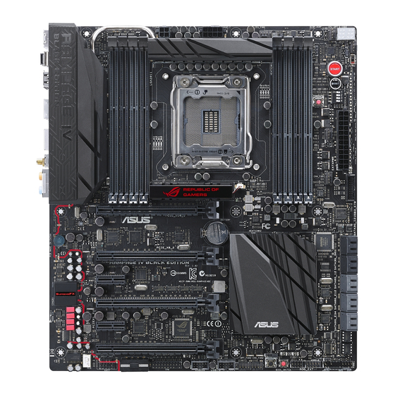
Page 24: Motherboard Layout
1.2.2 Motherboard layout Refer to section 1.2.9 Internal connectors and the section about the Rear I/O Connection on Chapter 2 for more information about the internal connectors and rear panel connectors. Chapter 1: Product introduction... - Page 25 BIOS Switch button 1-27 DirectKey button 1-26 Chassis intrusion connector (4-1 pin CHASSIS) 1-48 TPM connector (20-1 pin TPM) 1-48 Front panel audio connector (10-1 pin AAFP) 1-46 Digital audio connector (4-1 pin SPDIF_OUT) 1-44 ASUS RAMPAGE IV BLACK EDITION...
-
Page 26: Central Processing Unit (Cpu)
Contact your retailer immediately if the PnP cap is missing, or if you see any damage to the PnP cap/socket contacts/motherboard components. ASUS will shoulder the cost of repair only if the damage is shipment/ transit-related. -
Page 27: System Memory
The motherboard comes with four Double Data Rate 3 (DDR3) Dual Inline Memory Modules (DIMM) slots. A DDR3 module is notched differently from a DDR or DDR2 module. DO NOT install a DDR or DDR2 memory module to the DDR3 slot. Recommended memory configurations ASUS RAMPAGE IV BLACK EDITION 1-11... - Page 28 Memory configurations You may install 2GB, 4GB and 8GB unbuffered and non-ECC DDR3 DIMMs into the DIMM sockets. • You may install varying memory sizes in Channel A, Channel B, Channel C, and Channel D. The system maps the total size of the lower-sized channel for the dual- channel configuration.
- Page 29 RAMPAGE IV BLACK EDITION Motherboard Qualified Vendors List (QVL) DDR3 2800 MHz capacity DIMM socket support Chip Chip (Optional) Vendors Part No. Size Timing Voltage Brand CORSAIR CMD16GX3M4A2800C12 16GB (4x4GB) 12-14-14-36 1.65 • CORSAIR CMD16GX3M4A2800C11 16GB (4x4GB) 11-14-14-35 1.65 •...
- Page 30 DDR3 2400 MHz capacity DIMM socket support Chip Chip (Optional) Vendors Part No. Size Timing Voltage Brand G.SKILL F3-19200CL11Q- 16GB 11-11-11-31 1.65 • 16GBZHD (4x4GB) (XMP) G.SKILL F3-19200CL9D-4GBPIS 4G (2x2G ) 9-11-9-28 1.65 • (XMP) G.SKILL F3-19200CL9Q-16GBZMD 16GB 9-11-11-31 1.65 •...
- Page 31 (Optional) Vendors Part No. Size Chip NO. Timing Voltage Brand AEXEA AXA3ES4GK2000LG28V 1.65 • • (XMP) (2x2GB) Asint SLA302G08-ML2HB Hynix H5TQ2G83BFRH9C 9-9-9-27 • • (XMP) GEIL GUP34GB2000C9DC 9-9-9-28 1.65 • • (XMP) (2x2GB) ASUS RAMPAGE IV BLACK EDITION 1-15...
- Page 32 DDR3 1866 MHz capacity DIMM socket support Chip Vendors Part No. Size Chip NO. Timing Voltage (Optional) Brand 16GB A-DATA AX3U1866XW8G10(XMP) 10-11-10-30 • (2x8GB) CMD16GX3M4A1866C9 16GB CORSAIR 9-10-9-27 • (Ver4.13)(XMP) (4x4GB) CMD16GX3M4A1866C9 16GB CORSAIR 9-10-9-27 • • (Ver8.16)(XMP) (4x4GB) CMD32GX3M4A1866C9 32GB CORSAIR 9-10-9-27...
- Page 33 (2x8GB) 10-27 CML8GX3M2A1600C9 CORSAIR 9-9-9- 24 • (Ver7.12)(XMP) (2x4GB) 11-11- CORSAIR CMV8GX3M1A1600C11 • 11-30 CMX8GX3M2A1600C9 CORSAIR 9-9-9-24 1.65 • (Ver3.19)(XMP) (2x4GB) CMZ16GX3M2A1600C10 16GB 10-10- CORSAIR • (Ver.3.24)(XMP) (2x8GB) 10-27 (Continued on the next page) ASUS RAMPAGE IV BLACK EDITION 1-17...
- Page 34 DDR3 1600 MHz capacity DIMM socket support Chip Vendors Part No. Size Chip NO. Timing Voltage (Optional) Brand CMZ16GX3M4A1600C9 16GB 9-9-9- CORSAIR • (XMP) (4x4GB) CMZ16GX3M4X1600C9 16GB 1600-9- CORSAIR • • (Ver8.16)(XMP) (4x4GB) 9-9-24 CMZ32GX3M4X1600C10 32GB 10-10- CORSAIR • • (Ver2.2)(XMP) (4x8GB) 10-27...
- Page 35 TLD34G1600HC9BK 9-9-9- Team • • (XMP) (2x4GB) TLD38G1600HC9BK 16GB 9-9-9- Team • (XMP) (2x8GB) TXD34096M1600HC9- 9-9-9- Team Hynix H5TC2G83BFRH9A • • D(XMP) Transcend TS1GLK64V6H(620945) SAMSUNG K4B4G0846B • 11-11- Transcend TS1GLK64W6H SAMSUNG K4B4G0846B • 28-1 ASUS RAMPAGE IV BLACK EDITION 1-19...
- Page 36 DDR3 1333 MHz capacity DIMM socket support Vendors Part No. Size Chip Brand Chip NO. Timing Voltage (Optional) AE32G1339U1-U 23EY4587MB3H • AE34G1339U2-U 23EY4587MB3H • Apacer 78.B1GDE.9L10C Apacer AM5D5908CEHSBG • • Asint SLA302G08-EDJ1C ASint 302G08-DJ1C • Asint SLA304G08-EDJ1B Asint 304G08-DJ1B 9-10- •...
- Page 37 Hyper DIMM support is subject to the physical characteristics of individual CPUs. Load the X.M.P. or D.O.C.P. settings in the BIOS for the hyper DIMM support. • Visit the ASUS website for the latest QVL. ASUS RAMPAGE IV BLACK EDITION 1-21...
-
Page 38: Expansion Slots
1.2.5 Expansion slots Ensure to unplug the power cord before adding or removing expansion cards. Failure to do so may cause you physical injury and damage motherboard components. Slot No. Slot Description PCIe 3.0 x16_1 slot PCIe 3.0 x8_2 slot PCIe 2.0 x1_1 slot PCIe 3.0 x16/8_3 slot PCIe 2.0 x1_2 slot... - Page 39 PCIE_X1_1 shared ASM USB3#1 shared ASM USB3#2 shared ASM SATA6#1 shared ASM SATA6#2 shared Intel LAN 82579V shared On Chip USB1 shared On Chip USB2 shared HD Audio shared On Chip SATA shared ASUS RAMPAGE IV BLACK EDITION 1-23...
-
Page 40: Onboard Buttons And Switches
1.2.6 Onboard buttons and switches Onboard buttons and switches allow you to fine-tune performance when working on a bare or open-case system. This is ideal for overclockers and gamers who continually change settings to enhance system performance. Power-on (START) button The motherboard comes with a power-on button that allows you to power up or wake up the system. - Page 41 BIOS has been restored to its default settings. • We recommend that you download and update to the latest BIOS version from the ASUS website at www.asus.com after using the MemOK! function. ASUS RAMPAGE IV BLACK EDITION 1-25...
- Page 42 DirectKey button This feature allows your system to go to the BIOS Setup program with the press of a button. With DirectKey, you can enter the BIOS anytime without having to press the <Del> key during POST. It also allows you to turn on or turn off your system and conveniently enter the BIOS during boot-up.
- Page 43 These slide switches allows you to enable and disable the corresponding PCIe x16 slots. When one of the installed PCIe x16 cards is out of order, you can use the slide switch to find out the faulty one without removing the cards. ASUS RAMPAGE IV BLACK EDITION 1-27...
- Page 44 Slow Mode Switch Slow Mode Switch is employed during LN2 benching. Some processors have a small optimum temperature range to run at their highest frequency. Warmer or colder yields instability at this frequency. For example, a certain processor may need -80̊C loaded in order to run 5.8GHz, which means about -75̊C idle in order to stay stable at 5.8GHz.
-
Page 45: Onboard Leds
BIOS LED The BIOS LEDs help indicate the BIOS activity. Press the BIOS button to switch between BIOS1 and BIOS2 and the LED lights up when the corresponding BIOS is in use. ASUS RAMPAGE IV BLACK EDITION 1-29... - Page 46 MemOK! LED Blinking: Indicates that MemOK! is enabled before POST. Q LED Q LEDs check key components (CPU, DRAM, VGA card, and booting devices) in sequence during motherboard booting process. If an error is found , the corresponding LED will continue lighting until the problem is solved. This user-friendly design provides an intuitive way to locate the root problem within seconds.
- Page 47 The illustration below shows the location of the onboard power-on button. Q-Code LEDs The Q-Code LED design provides you with a 2-digit error code that displays the system status. Refer to the Q-Code table on the next page for details. ASUS RAMPAGE IV BLACK EDITION 1-31...
- Page 48 Q-Code table Code Description Not used Power on. Reset type detection (soft/hard). AP initialization before microcode loading System Agent initialization before microcode loading PCH initialization before microcode loading Microcode loading AP initialization after microcode loading System Agent initialization after microcode loading PCH initialization after microcode loading Cache initialization 0C –...
- Page 49 Recovery condition triggered by user (Forced recovery) Recovery process started Recovery firmware image is found Recovery firmware image is loaded F5 – F7 Reserved for future AMI progress codes Recovery PPI is not available (continued on the next page) ASUS RAMPAGE IV BLACK EDITION 1-33...
- Page 50 Q-Code table Code Description Recovery capsule is not found Invalid recovery capsule FB – FF Reserved for future AMI error codes DXE Core is started NVRAM initialization Installation of the PCH Runtime Services 63 – 67 CPU DXE initialization is started PCI host bridge initialization System Agent DXE initialization is started System Agent DXE SMM initialization is started...
- Page 51 USB hot plug PCI bus hot plug Clean-up of NVRAM Configuration Reset (reset of NVRAM settings) B8– BF Reserved for future AMI codes CPU initialization error System Agent initialization error (continued on the next page) ASUS RAMPAGE IV BLACK EDITION 1-35...
- Page 52 Q-Code table Code Description PCH initialization error Some of the Architectural Protocols are not available PCI resource allocation error. Out of Resources No Space for Legacy Option ROM No Console Output Devices are found No Console Input Devices are found Invalid password Error loading Boot Option (LoadImage returned error) Boot Option is failed (StartImage returned error)
-
Page 53: Jumper
Jumper LN2 Mode jumper (3-pin LN2) With LN2 mode activated, the ROG motherboard is optimized to remedy the cold- boot bug during POST at an extremely low temperature and help the system boot successfully. ASUS RAMPAGE IV BLACK EDITION 1-37... -
Page 54: Internal Connectors
1.2.9 Internal connectors Intel X79 Serial ATA 6.0 Gb/s connectors (7-pin SATA6G_1; SATA6G_2 [gray]) ® These connectors connect to Serial ATA 6.0 Gb/s hard disk drives via Serial ATA 6.0 Gb/s signal cables. If you installed Serial ATA hard disk drives, you can create a RAID 0, 1, 5, and 10 configuration with the Intel Rapid Storage Technology through the onboard Intel ®... - Page 55 ATA RAID set using these connectors, set the SATA Mode item in the BIOS to [RAID Mode]. Refer to section 3.6.5 SATA Configuration for details. Before creating a RAID set, refer to section 5.1 RAID configurations or the manual • bundled in the motherboard support DVD. ASUS RAMPAGE IV BLACK EDITION 1-39...
- Page 56 ASMedia Serial ATA 6.0 Gb/s connectors (7-pin SATA6G_E1; SATA6G_E2; ® SATA6G_E3; SATA6G_E4 [gray]) These connectors connect to Serial ATA 6.0 Gb/s hard disk drives via Serial ATA 6.0 Gb/s signal cables. • ASMedia storage controller can only support AHCI mode. •...
- Page 57 Enable OPT FAN1/ OPT FAN2/ OPT FAN3 overheat protection in BIOS if you connect thermal sensor cables to these connectors. • Thermal sensor cables or thermistors are purchased separately. • To monitor the temperature at the BIOS, go to BIOS>Monitor>Temperature Monitor. ASUS RAMPAGE IV BLACK EDITION 1-41...
- Page 58 Never connect a 1394 cable to the USB connectors. Doing so will damage the motherboard! You can connect the front panel USB cable to the ASUS Q-Connector (USB) first, and then install the Q-Connector (USB) to the USB connector onboard if your chassis supports front panel USB ports.
- Page 59 This connector is for an additional Sony/Philips Digital Interface (S/PDIF) port(s). Connect the S/PDIF Out module cable to this connector, then install the module to a slot opening at the back of the system chassis. The S/PDIF module is purchased separately. ASUS RAMPAGE IV BLACK EDITION 1-43...
- Page 60 CPU, chassis, and power fan connectors (4-pin CPU_FAN; 4-pin CPU_OPT; 4-pin CHA_FAN1/ CHA_FAN2/ CHA_FAN3; 4-pin OPT_FAN1/ OPT_FAN2 / OPT_FAN3) Connect the fan cables to the fan connectors on the motherboard, ensuring that the black wire of each cable matches the ground pin of the connector. Do not forget to connect the fan cables to the fan connectors.
- Page 61 Front Panel Type item in the BIOS setup to [HD]; if you want to connect an AC'97 front panel audio module to this connector, set the item to [AC97]. By default, this connector is set to [HD]. ASUS RAMPAGE IV BLACK EDITION 1-45...
- Page 62 DirectKey connector (2-pin DRCT) This connector is for the chassis-mounted button that supports the DirectKey function. Connect the button cable that supports DirectKey, from the chassis to this connector on the motherboard. Ensure that your chassis comes with the extra button cable that supports the DirectKey feature.
- Page 63 The signal is then generated as a chassis intrusion event. By default, the pin labeled “Chassis Signal” and “Ground” are shorted with a jumper cap. Remove the jumper caps only when you intend to use the chassis intrusion detection feature. ASUS RAMPAGE IV BLACK EDITION 1-47...
- Page 64 • If you are uncertain about the minimum power supply requirement for your system, refer to the Recommended Power Supply Wattage Calculator at http://support.asus.com/PowerSupplyCalculator/PSCalculator.aspx? SLanguage=en-us for details. Chapter 1: Product introduction 1-48...
- Page 65 Pressing the power switch for more than four seconds while the system is ON turns the system OFF. • Reset button (2-pin RESET) This 2-pin connector is for the chassis-mounted reset button for system reboot without turning off the system power. ASUS RAMPAGE IV BLACK EDITION 1-49...
-
Page 66: Probeit
1.2.10 ProbeIt The ROG ProbeIt allows you to detect your system’s current voltage and OC settings. Use a multimeter to measure the ProbeIt points even during overclocking. See the illustration below to locate the respective ProbeIt points. Using ProbeIt You may connect the multitester to the motherboard as shown on the following figure. The illustration above are for reference only, the actual motherboard layout and measure points location may differ by models. -
Page 67: Chapter 2: Basic Installation
The diagrams in this section are for reference only. The motherboard layout may vary with models, but the installation steps are the same for all models. Install the ASUS Q-Shield to the chassis rear I/O panel. Place the motherboard into the chassis, ensuring that its rear I/O ports are aligned to the chassis’... - Page 68 Place nine screws into the holes indicated by circles to secure the motherboard to the chassis. DO NOT overtighten the screws! Doing so can damage the motherboard. Chapter 2: Basic Installation...
-
Page 69: Cpu Installation
Please note the order in opening/ closing the double latch. Follow the instructions printed on the metal sealing hatch or the illustrations shown below in this manual. The plastic cap will pop up automatically once the CPU is in place and the hatch properly sealed down. ASUS RAMPAGE IV BLACK EDITION... - Page 70 Triangle mark Triangle mark Chapter 2: Basic Installation...
-
Page 71: Cpu Heatsink And Fan Assembly Installation
2.1.3 CPU heatsink and fan assembly installation Apply the Thermal Interface Material to the CPU heatsink and CPU before you install the heatsink and fan, if necessary. To install the CPU heatsink and fan assembly ASUS RAMPAGE IV BLACK EDITION... - Page 72 To replace the LGA2011 CPU pad (X-Socket) • The X-Socket is a unique ROG feature that allows user to use their LGA 1366 cooler on the LGA 2011 motherboard. • For the detailed QVL list, visit http://event.asus.com/2011/rog/X-Socket/. Chapter 2: Basic Installation...
-
Page 73: Dimm Installation
2.1.4 DIMM installation To remove a DIMM ASUS RAMPAGE IV BLACK EDITION... -
Page 74: Atx Power Connection
2.1.5 ATX Power connection Chapter 2: Basic Installation... -
Page 75: Sata Device Connection
2.1.6 SATA device connection ASUS RAMPAGE IV BLACK EDITION... -
Page 76: Front I/O Connector
2.1.7 Front I/O Connector To install ASUS Q-Connector To install USB 2.0 connector To install front panel audio connector AAFP USB 2.0 To install USB 3.0 connector USB 3.0 Chapter 2: Basic Installation 2-10... -
Page 77: Expansion Card Installation
2.1.8 Expansion Card installation To install PCIe x16 cards To install PCIe x1 cards ASUS RAMPAGE IV BLACK EDITION 2-11... -
Page 78: Wi-Fi Antenna Installation
2.1.9 Wi-Fi antenna installation Installing the ASUS 2T2R dual band W-Fi antenna Connect the bundled ASUS 2T2R dual band Wi-Fi antenna connector to the Wi-Fi ports at the back of the chassis. IO Shield • Ensure that the ASUS 2T2R dual band Wi-Fi antenna is securely installed to the Wi-Fi ports. -
Page 79: Bios Update Utility
• Updating BIOS may have risks. If the BIOS program is damaged during the process and results to the system’s failure to boot up, please contact your local ASUS Service Center. ASUS RAMPAGE IV BLACK EDITION... -
Page 80: Motherboard Rear And Audio Connections
Motherboard rear and audio connections 2.3.1 Rear I/O connection Rear panel connectors 1. PS/2 mouse and keyboard port 2. Clear CMOS button 3. USB 2.0 ports 3 and 4 (The ROG Connect port is the port on top.) 4. USB 3.0 ports 3 and 4 5. - Page 81 Front Speaker Out Front Speaker Out Front Speaker Out Pink Mic In Mic In Mic In Mic In Orange – – Center/Subwoofer Center/Subwoofer Black – Rear Speaker Out Rear Speaker Out Rear Speaker Out ASUS RAMPAGE IV BLACK EDITION 2-15...
-
Page 82: Audio I/O Connections
2.3.2 Audio I/O connections Audio I/O ports Connect to Headphone and Mic Connect to Stereo Speakers Connect to 2.1 channel Speakers Chapter 2: Basic Installation 2-16... - Page 83 Connect to 4.1 channel Speakers Connect to 5.1 channel Speakers Connect to 7.1 channel Speakers ASUS RAMPAGE IV BLACK EDITION 2-17...
-
Page 84: Oc Panel
Ensure that your system has adequate cooling designed for overclocking before using the OC Panel. • Ensure to update your OC Panel’s firmware. Visit www.asus.com for the latest firmware and updates about the OC Panel. • Ensure that you have installed ROG Connect Plus driver for the NORMAL Mode of the OC Panel. - Page 85 OC Panel LCM Display in Normal Mode OC Panel LCM Display in Extreme Mode ASUS RAMPAGE IV BLACK EDITION 2-19...
-
Page 86: Setting Up Your Oc Panel In Normal Mode
2.4.2 Setting up your OC Panel in Normal Mode Ensure that you have installed ROG Connect Plus driver for the NORMAL Mode of the OC Panel. The OC Panel in Normal Mode mainly provides easy access buttons for increasing your CPU’s frequency level, adjusting fan speeds and customizing overclocking profiles. - Page 87 SATA Power cable (B) to the OC Panel. Locate the ROG_EXT connector on the motherboard and connect the OC Panel cable. Boot your computer. Press the OC Panel LCM Power button to turn on the OC Panel LCM display. ASUS RAMPAGE IV BLACK EDITION 2-21...
-
Page 88: Setting Up Your Oc Panel In Extreme Mode
2.4.3 Setting up your OC Panel in Extreme Mode The OC Panel in Extreme Mode is setup with an open chassis system or “open-air” OC test bed assembly and enjoyed as a handheld console to perform overclocking and voltage tuning. When in Extreme Mode, you can enjoy more features including Subzero Sense and VGA Hotwire. -
Page 89: Starting Up For The First Time
While the system is ON, press the power button for less than four seconds to put the system on sleep mode or soft-off mode, depending on the BIOS setting. Press the power switch for more than four seconds to let the system enter the soft-off mode regardless of the BIOS setting. ASUS RAMPAGE IV BLACK EDITION 2-23... - Page 90 Chapter 2: Basic Installation 2-24...
-
Page 91: Chapter 3: Bios Setup
BIOS setup Knowing BIOS The new ASUS UEFI BIOS is a Unified Extensible Interface that complies with UEFI architecture, offering a user-friendly interface that goes beyond the traditional keyboard- only BIOS controls to enable a more flexible and convenient mouse input. You can easily navigate the new UEFI BIOS with the same smoothness as your operating system. -
Page 92: Bios Setup Program
BIOS setup program Use the BIOS Setup to update the BIOS or configure its parameters. The BIOS screen include navigation keys and brief onscreen help to guide you in using the BIOS Setup program. Entering BIOS at startup To enter BIOS Setup at startup, press <Delete> during the Power-On Self Test (POST). If you do not press <Delete>, POST continues with its routines. -
Page 93: Ez Mode
Power Saving mode • The boot device options vary depending on the devices you installed to the system. The Boot Menu (F8) button is available only when the boot device is installed to the • system. ASUS RAMPAGE IV BLACK EDITION... -
Page 94: Advanced Mode
3.2.2 Advanced Mode The Advanced Mode provides advanced options for experienced end-users to configure the BIOS settings. The figure below shows an example of the Advanced Mode. Refer to the following sections for the detailed configurations. To access the Advanced Mode, click Exit, then select Advanced Mode or press F7 hotkey. Submenu items Menu bar General help... - Page 95 The Quick Note function does not support the following keyboard functions: delete, cut, copy and paste. • You can only use the alphanumeric characters to enter your notes. Last Modified button This button shows the items that you last modified and saved in BIOS Setup. ASUS RAMPAGE IV BLACK EDITION...
-
Page 96: My Favorites
My Favorites MyFavorites is your personal space where you can easily save and access your favorite BIOS items. Adding items to My Favorites To add frequently-used BIOS items to My Favorites: Use the arrow keys to select an item that you want to add. When using a mouse, hover the pointer to the item. -
Page 97: Extreme Tweaker Menu
Load 180BCLK OC Profile/ Load 190BCLK OC Profile Select any of these preset overclocking profiles to load your preferred overclocking option. The profiles appearing on the BIOS screen may vary depending on the CPU installed on your motherboard. ASUS RAMPAGE IV BLACK EDITION... - Page 98 Ai Overclock Tuner [Auto] Allows you to select the CPU overclocking options to achieve the desired CPU internal frequency. Select any of these preset overclocking configuration options: [Auto] Loads the optimal settings for the system. [Manual] Allows you to individually set overclocking parameters. [X.M.P.] If you install memory modules supporting the eXtreme Memory Profile (X.M.P.) Technology, choose this item to set the profiles supported by your...
- Page 99 Allows you to set the memory operating frequency. The configuration options vary with the BCLK/CPU Strap Frequency item settings. Xtreme Tweaking [Disabled] Allows you to enable or disable Xtreme Tweaking that helps improve some benchmark performance. Configuration options: [Enabled] [Disabled] ASUS RAMPAGE IV BLACK EDITION...
- Page 100 EPU Power Saving Mode [Disabled] Allows you to enable or disable the EPU power saving function. Configuration options: [Disabled] [Enabled] The following item only appears when you set EPU Power Saving Mode to [Enabled]. EPU Setting [Auto] Allows you to select the EPU power saving function. Configuration options: [Auto] [Light Power Saving] [Medium Power Saving] [Max Power Saving] DRAM Timing Control...
- Page 101 Configuration options: [Auto] [0 DRAM Clock] – [7 DRAM Clock] tRWDR [Auto] Configuration options: [Auto] [0 DRAM Clock] – [15 DRAM Clock] tRWDD [Auto] Configuration options: [Auto] [0 DRAM Clock] – [15 DRAM Clock] ASUS RAMPAGE IV BLACK EDITION 3-11...
- Page 102 Third Timings tWRDR [Auto] Configuration options: [Auto] [0 DRAM Clock] – [7 DRAM Clock] tWRDD [Auto] Configuration options: [Auto] [0 DRAM Clock] – [7 DRAM Clock] tRWSR [Auto] Configuration options: [Auto] [0 DRAM Clock] – [15 DRAM Clock] tCCD [Auto] Configuration options: [Auto] [0 DRAM Clock] –...
- Page 103 CPU Power Duty Control [T.Probe] [T.Probe] Maintains the VRM thermal balance. [Extreme] Maintains the VRM current balance. Vcore MOS volt. Control [Auto] Configuration options: [Auto] [6V] [6.5V] [7V] [7.5V] [8V] [8.5V] [9V] [9.5V] [10V] ASUS RAMPAGE IV BLACK EDITION 3-13...
- Page 104 Reducing phase number under light system loading to increase VRM efficiency [Standard] Proceeds phase control depending on the CPU loading. [Optimized] Loads the ASUS optimized phase tuning profile. [Extreme] Proceeds the full phase mode. [Manual Adjustment] Allows manual adjustment.
- Page 105 Configuration options: [Auto] [manual] DRAM-AB/DRAM-CD Power Phase control [Standard] [Standard] Allows you to set to the standard phase tuning profile. [Optimized] Allows you to set ASUS optimized phase tuning profile. [Extreme] Allows you to set the Full phase mode. PCH 1.1V PCH 1.1v Switching Freq.
- Page 106 CPU Performace Settings Enhanced Intel SpeedStep Technology [Auto] Allows you to enable or disable the Enhanced Intel SpeedStep Technology. ® [Auto] Automatically selects the function. [Disabled] Disables this function. [Enabled] The operating system dynamically adjusts the processor voltage and core frequency which may result in decreased average consumption and decreased average heat production.
- Page 107 CPU permanently, and setting a low voltage may make the system unstable. 2nd VTTCPU Voltage [Auto] Allows you to set the second VTTCPU voltage. The values range from 0.80642V to 1.70538V with an increment of 0.00661V. ASUS RAMPAGE IV BLACK EDITION 3-17...
- Page 108 CPU VCCSA Voltage [Manual Mode] • [Manual Mode] Allows you to set a fixed CPU voltage. • [Offset Mode] Allows you to set the Offset voltage. This item appears only when you set the CPU VCCSA Voltage item to [Manual Mode] CPU VCCSA Manual Voltage [Auto] This item allows you to set a fixed CPU voltage.
- Page 109 Configuration options: [Auto] [-1 to -63] - [+1 to +63] CPU I/O Drive Strenght [Auto] Linearly related to CPU I/O Skew. Default is 0 and can increase when CPU is colder. Configuration options: [Auto] [-1 t0 -63] - [+1 to +63] ASUS RAMPAGE IV BLACK EDITION 3-19...
- Page 110 Memory Tweakers’ Paradise IMC AB Signal 1 / Signal 2 / Signal 3 [Auto] Configuration options: [-126] – [-1] [Auto] [+1] – [+32] IMC CD Signal 1 / Signal 2 / Signal 3 [Auto] Configuration options: [-126] – [-1] [Auto] [+1] – [+32] DRAM CTRL REF Voltage on (CHA) / (CHB) / (CHC) / (CHD) [Auto] The values range from 0.38500x to 0.61500x with a 0.0050x interval.
-
Page 111: Main Menu
Chapter 3 for information on how to erase the RTC RAM via the Clear CMOS button. • The Administrator or User Password items on top of the screen show the default [Not Installed]. After you set a password, these items show [Installed]. ASUS RAMPAGE IV BLACK EDITION 3-21... - Page 112 Administrator Password If you have set an administrator password, we recommend that you enter the administrator password for accessing the system. Otherwise, you might be able to see or change only selected fields in the BIOS setup program. To set an administrator password: Select the Administrator Password item and press <Enter>.
-
Page 113: Advanced Menu
The Advanced menu items allow you to change the settings for the CPU and other system devices. Be cautious when changing the settings of the Advanced menu items. Incorrect field values can cause the system to malfunction. ASUS RAMPAGE IV BLACK EDITION 3-23... -
Page 114: Cpu Configuration
3.6.1 CPU Configuration The items in this menu show the CPU-related information that the BIOS automatically detects. The items in this menu may vary based on the CPU installed. Intel Adaptive Thermal Monitor [Enabled] [Enabled] Enables the overheated CPU to throttle its clock speed to cool down. [Disabled] Disables the CPU thermal monitor function. - Page 115 Configuration options: [Disabled] [Enabled] CPU C3 Report [Disabled] Configuration options: [Disabled] [Enabled] CPU C6 Report [Enabled] Configuration options: [Disabled] [Enabled] Package C State limit [Auto] Configuration options: [Auto] [C0] [C2] [C6] [C7] [No Limit] ASUS RAMPAGE IV BLACK EDITION 3-25...
-
Page 116: System Agent Configuration
3.6.2 System Agent Configuration PCIE_X16_1 / PCIE_X16/8_3 and PCIE_X8_4 / PCIE_X8_2 Link Speed [GEN3] Allows you to select the target link speed. Configuration options: [Auto] [Gen1] [Gen2] [Gen3] 3.6.3 PCH Configuration High Precision Timer [Enabled] Allows you to enable or disable the High Precision Event Timer. Configuration options: [Disabled] [Enabled] Chapter 3: BIOS setup 3-26... -
Page 117: Sata Configuration
[RAID Mode] Set to [RAID Mode] when you want to create a RAID configuration from the SATA hard disk drives. To rename the Intel SATA port, click on the item then key-in your desired name. ASUS RAMPAGE IV BLACK EDITION 3-27... - Page 118 The following two items appear only when you set the SATA Mode item to [IDE Mode]. Serial-ATA Controller 0 [Enabled] Allows you to enabled/disabled the Serial-ATA Controller 0. Configuration options: [Disabled] [Enabled] [Compatible] Serial-ATA Controller 1 [Enabled] Allows you to enabled/disabled the Serial-ATA Controller 1. Configuration options: [Disabled] [Enabled] S.M.A.R.T.
-
Page 119: Usb Configuration
Disables the EHCI Hand-off support. USB Per Port Control Allows you to enable or disable the individual USB port. Refer to the Motherboard layout on Chapter 1 for the location of the USB ports. ASUS RAMPAGE IV BLACK EDITION 3-29... -
Page 120: Onboard Devices Configuration
3.6.6 Onboard Devices Configuration Scroll down to view the other BIOS items. Azalia HD Audio [Enabled] • [Disabled] Disables the controller. • [Enabled] Enables the High Definition Audio Controller. The following two items appear only when you set the Azalia HD Audio item to [Enabled]. Front Panel Type [HD] Allows you to set the front panel audio connector (AAFP) mode to legacy AC97 or high- definition audio depending on the audio standard that the front panel audio module... - Page 121 If you want to use the full function of the ASM1061 storage controller like theAHCI, we recommend that you set this item to [AHCI Mode] and install the ASM1061 Controller Driver from the motherboard support DVD. Hot-plug [Disabled] [Disabled] Disables the hot-plug support. [Enabled] Enables the hot-plug support. ASUS RAMPAGE IV BLACK EDITION 3-31...
-
Page 122: Apm
3.6.7 Restore AC Power Loss [Power Off] [Power On] The system goes into ON state after an AC power loss. [Power Off] The system goes into OFF state after an AC power loss. [Last State] The system goes into either OFF or ON state, whatever the system state was before the AC power loss. -
Page 123: Network Stack
This item allows the animation of the ROG Logo on the upper left corner of the BIOS UEFI screen when set to [Enabled]. Configuration options: [Disabled] [Enabled] SupremeFX Lighting LED [Enabled] Allows you to enable ot disable the LED for SupremeFX application. Configuration options: [Disabled] [Enabled] ASUS RAMPAGE IV BLACK EDITION 3-33... -
Page 124: Monitor Menu
Monitor menu The Monitor menu displays the system temperature/power status, and allows you to change the fan settings. Anti Surge Support [Enabled] This item allows you to enable or disable the Anti Surge function. Configuration options: [Disabled] [Enabled] Voltage Monitor CPU Voltage;... - Page 125 Use the <+> and <-> keys to adjust the minimum CPU fan duty cycle. The values range from 40% to 100%. When the CPU temperature is under its CPU lower temperature setting, the CPU fan will operate at the minimum duty cycle. ASUS RAMPAGE IV BLACK EDITION 3-35...
- Page 126 Chassis Q-Fan Control 1-3 [Disabled] [Disabled] Disables the Chassis Q-Fan control feature. [Enabled] Enables the Chassis Q-Fan control feature. Chassis Fan Speed Low Limit 1-3 [600 RPM] This item appears only when you enable the Chassis Q-Fan Control feature and allows you to disable or set the chassis fan warning speed.
- Page 127 Allows you to set the optional fans’ low speed temperature. Configuration options: [25%] [30%] [35%] [40%] OPT1-3 Full Speed Temp [60%] Allows you to set the optional fans’ full speed temperature. Configuration options: [60%] [70%] [80%] [90%] ASUS RAMPAGE IV BLACK EDITION 3-37...
-
Page 128: Boot Menu
Boot menu The Boot menu items allow you to change the system boot options. Scroll down to display the other BIOS items. Fast Boot [Disabled] [Disabled] Allows your system to go back to its normal boot speed. [Enabled] Allows your system to accelerate the boot speed. The following items appear only when you set the Fast Boot to [Enabled]. - Page 129 The following items appears only when you set the Boot Logo Display item to [Disabled]. POST Report [5 sec] This item allows you to select a desired POST report waiting time. Configuration options: [1 sec] - [2 sec] [Until Press ESC] ASUS RAMPAGE IV BLACK EDITION 3-39...
- Page 130 Bootup NumLock State [On] Set the power-on state of the NumLock to [On]. [On] Set the power-on state of the NumLock to [Off]. [Off] Wait For ‘F1’ If Error [Enabled] [Disabled] Disables the function. [Enabled] The system waits for the <F1> key to be pressed when error occurs. Option ROM Messages [Force BIOS] [Force BIOS] The third-party ROM messages will be forced to display during the boot...
- Page 131 [Legacy OPROM first] [UEFI driver first] [Ignore] Boot from PCIe Expansion Devices [Legacy OPR...] Allows you to select the type of PCIe/PCI expansion devices that you want to launch. Configuration options: [Legacy OPROM first] [UEFI driver first] ASUS RAMPAGE IV BLACK EDITION 3-41...
- Page 132 Press <F5> when ASUS Logo appears. Press <F8> after POST. • To select the boot device during system startup, press <F8> when ASUS Logo appears. Boot Override These items displays the available devices. The number of device items that appears on the screen depends on the number of devices installed in the system.
-
Page 133: Tools Menu
3.9.1 ASUS EZ Flash 2 Utility Allows you to run ASUS EZ Flash 2. When you press <Enter>, a confirmation message appears. Use the left/right arrow key to select between [Yes] or [No], then press <Enter> to confirm your choice. -
Page 134: Rog Ssd Secure Erase
To launch ROG SSD Secure Erase, click Tool > ROG SSD Secure Erase on the Advanced mode menu. Check the ASUS support site for a full list of SSDs tested with Secure Erase. The drive may become unstable if you run Secure Erase on an incompatible SSD. -
Page 135: Asus Spd Information
3.9.3 ASUS SPD Information Allows you to view the DRAM SPD information. DIMM Slot Number Allows you to view the information about the installed DIMMS when selected. ASUS RAMPAGE IV BLACK EDITION 3-45... -
Page 136: Asus Overclocking Profile
3.9.4 ASUS Overclocking Profile This item allows you to store or load multiple BIOS settings. The O.C. Profile Configuration items show Not Installed if no profile is created. Profile Name Allows you to input the label of the setup profiles. -
Page 137: Bios Flashback
CPU input voltage, BCLK Frequency, and CPU ratio in the UEFI BIOS. The saved values can be synchronized to a compatible OC Panel device and these values can be applied to the motherboard using the OC Panel without going to the BIOS menu. ASUS RAMPAGE IV BLACK EDITION 3-47... - Page 138 BCLK Frequency [Auto] This item allows you to input values to the Base Clock (BCLK) Frequency that ranges from 80 MHz to 300 MHz. CPU Ratio [Auto] This item allows you to the adjust the CPU ratio. The CPU ratio may vary according to the model of the processor.
-
Page 139: Exit Menu
This option allows you to enter the EZ Mode screen. Launch EFI Shell from filesystem device This option allows you to attempt to launch the EFI Shell application (shellx64.efi) from one of the available filesystem devices. ASUS RAMPAGE IV BLACK EDITION 3-49... -
Page 140: Updating Bios
Inappropriate BIOS updating may result in the system’s failure to boot. Carefully follow the instructions of this chapter to update your BIOS if necessary. Visit the ASUS website at www.asus.com to download the latest BIOS file for this motherboard. The following utilities allow you to manage and update the motherboard BIOS setup program. -
Page 141: Asus Ez Flash 2
3.11.1 ASUS EZ Flash 2 ASUS EZ Flash 2 allows you to update the BIOS without having to use a bootable floppy disk or an OS-based utility. Before you start using this utility, download the latest BIOS from the ASUS website at www.asus.com. -
Page 142: Asus Crashfree Bios 3
The BIOS file in the motherboard support DVD may be older than the BIOS file published on the ASUS official website. If you want to use the newer BIOS file, download the file at support.asus.com and save it to a USB flash drive. -
Page 143: Asus Bios Updater
3.11.3 ASUS BIOS Updater The ASUS BIOS Updater allows you to update the BIOS in DOS environment. This utility also allows you to copy the current BIOS file that you can use as a backup when the BIOS fails or gets corrupted during the updating process. - Page 144 D:\>bupdater /pc /g The BIOS Updater screen appears as below. ASUSTek BIOS Updater for DOS V1.30 [2012/05/22] FLASH TYPE: MX1C 25L1065A Current ROM Update ROM BOARD: BOARD: RAMPAGE IV BLACK EDITION UNKNOWN VER: 0204 VER: UNKNOWN DATE: 01/01/2012 DATE: UNKNOWN PATH: R4BE.CAP...
- Page 145 Select the Load Optimized Defaults item under the Exit BIOS menu. See Chaper 3 BIOS setup of your motherboard user manual for details. • Ensure to connect all SATA hard disk drives after updating the BIOS file if you have disconnected them. ASUS RAMPAGE IV BLACK EDITION 3-55...
- Page 146 Chapter 3: BIOS setup 3-56...
-
Page 147: Chapter 4: Software Support
Support DVD information The contents of the support DVD are subject to change at any time without notice. Visit the ASUS website at www.asus.com for updates. 4.2.1 Running the support DVD Ensure that you have an Administrator account before running the support DVD in To run the support DVD Place the Support DVD into the optical drive. - Page 148 ROG drivers to use the devices. related videos. Click the The Utilities Contact tab menu shows to display the the applications ASUS contact and other information. software that the motherboard supports. Click an icon to display DVD/ motherboard information...
-
Page 149: Obtaining The Software Manuals
Some software manuals are provided in different languages. Open the language’s folder to view the software manual. The screenshots in this section are for reference only. The actual software manuals containing in the support DVD vary by models. ASUS RAMPAGE IV BLACK EDITION... -
Page 150: Software Information
View the online help or readme file that came with the software application for more information. AI Suite 3 AI Suite 3 is an all-in-one interface that integrates several ASUS utilities and allows you to launch and operate these utilities simultaneously. Installing AI Suite 3 •... - Page 151 Launching AI Suite 3 Windows 7 OS ® From the Desktop, click Start > All Programs > ASUS > AI Suite 3 > AI Suite 3. You can also launch AI Suite 3 in Windows 7 by clicking on the Notification area.
- Page 152 Some functions in the AI Suite 3 main menu in this user manual may vary depending on the motherboard model. • Refer to the software manual in the support DVD or visit the ASUS website at www.asus.com for detailed software configuration. Chapter 4: Software support...
-
Page 153: Dual Intelligent Processors 4 With 4-Way Optimization
Click or tap this 4-Way Optimization Click or tap to view the 4-Way button to auto-detect and tune the best Optimization report settings for your system DO NOT remove your fan during the tuning process. ASUS RAMPAGE IV BLACK EDITION... - Page 154 Using 4-Way Optimization Click or tap the 4-Way Optimization button then click or tap Start to auto-detect the best settings based on actual usage. Click or tap to go back to Click or tap to view Click or tap to start the 4-Way Optimization more settings auto-tuning...
- Page 155 TPU. Refer to section Extreme Tweaker menu in the BIOS chapter of your motherboard user manual for details. • The CPU Frequency bars show the status of the CPU cores, which vary with your CPU model. ASUS RAMPAGE IV BLACK EDITION...
- Page 156 CPU Strap Drag the slider to adjust the CPU Strap’s BCLK (base clock) frequency Click to apply CPU Strap settings Click to cancel the CPU Strap settings Click to apply the adjustments Click to undo the Click to load adjustments Click to save the the saved adjustment into a...
- Page 157 Away Mode and move the sliders to adjust monitor and system sleep time Click or tap to apply the adjustments Click or tap to apply the Click or tap to undo the default settings adjustments ASUS RAMPAGE IV BLACK EDITION 4-11...
- Page 158 Max Power Saving Tick to select Voltage Decrement setting Tick to enable Away Mode Move the sliders to adjust monitor and system sleep time Click or tap to apply the adjustments Click or tap to apply the Click or tap to select a Click or tap to undo the default settings fan profile...
- Page 159 CPU Power Phase Control Allows you to select between Standard, Optimized, Extreme, and Manual Adjustment modes. The modes allows you to either increase system performance or increase the DRAM power efficiency. ASUS RAMPAGE IV BLACK EDITION 4-13...
- Page 160 Click or tap to switch Click or tap to undo Click or tap to between screens the changes apply the changes CPU Voltage Frequency CPU Voltage Frequency affects the VRM transient response and thermal conditions. Higher VRM frequency gets a quicker transient response. When Auto is selected, you have an option to enable CPU Spread Spectrum that helps enhance system stability.
- Page 161 DRAM-AB Power Phase Control For DRAM slots A or B, select Extreme for full phase mode to increase system performance or select Optimized for ASUS optimized phase tuning profile to increase the DRAM power efficiency. DRAM-CD Power Phase Control...
- Page 162 Fan Xpert 2 Fan Xpert 2 automatically detects and tweaks the fan speeds and provides you with optimized fan settings based on the fans’ specifications and positions. Using Fan Xpert 2 Click or tap to set the fan’s speed to silent mode Select a screen to select the type of fan that you want...
- Page 163 Fan Xpert 2 only supports fans with 4-pin and 3-pin connectors. If you install a 2-pin fan, it can only run at its full speed. • If you change the CPU or chassis fans, you must repeat the Fan Auto Tuning process. ASUS RAMPAGE IV BLACK EDITION 4-17...
-
Page 164: Ai Charger
4.4.2 Ai Charger+ Ai Charger+ allows you to fast-charge your portable BC 1.1* mobile devices on your computer’s USB port three times faster than the standard USB devices**. Launching Ai Charger+ To launch Ai Charger+, click or tap on the top-right corner of the AI Suite 3 main menu, then select Ai Charger+. -
Page 165: Wi-Fi Engine
The Client mode allows you to connect your system to a wireless network. To use the client mode: Click or tap Client Mode to launch Network Connections. From the Network Connections window, select a network adapter. ASUS RAMPAGE IV BLACK EDITION 4-19... - Page 166 From the list of available networks, select a network that you want to connect to. Using the AP Mode The AP mode allows you to set your system as an access point for other wireless-enabled devices. To use AP mode, click or tap AP Mode on the Wi-Fi Engine menu. Key in a network name Key in your...
-
Page 167: Wi-Fi Go
4.4.4 Wi-Fi GO! Wi-Fi GO! is an ASUS-exclusive Wi-Fi utility that allows you to wirelessly stream your media files to HDTV device/display, control your computer using your smart device, transfer files to your smart device, and provides access to your files stored in your cloud storage. - Page 168 Launching Wi-Fi GO! To launch Wi-Fi GO!, click or tap the on the top-right corner of the AI Suite 3 main menu, then select Wi-Fi GO! Click or tap to set a password Wi-Fi GO! menu Chapter 4: Software support 4-22...
- Page 169 • Ensure that the ASUS AI Suite 3 utility is active when using Wi-Fi GO!. Wi-Fi GO! & NFC Remote Wi-Fi GO! & NFC Remote allows you to remotely control your computer using your smart device.
- Page 170 Click or tap Cloud GO! > Enter. Log in to your cloud accounts, then click or tap Sign In. • To log in to your ASUS Webstorage account, key in your user name and password. accounts, click or tap Sign in. Cloud •...
- Page 171 Tick the cloud storage account then click or tap OK. Tick Backup if you want to save • a backup in your computer. • All synced files are stored in the Wi-Fi GO! folder. ASUS RAMPAGE IV BLACK EDITION 4-25...
- Page 172 Using Cloud GO! in your smart device To use Cloud GO! in your smart device, tap Cloud GO! > Enter. You must log in to your computer first and tick Remember me to authorize access in your smart device. Tap to open cloud storage accounts Tap a specific icon to move, upload,...
- Page 173 8 / 8.1 ® Tap to view the cursor Tap to launch the Charms bar Tap to launch the smart device’s keypad Remote Desktop interface for Windows ® Tap to launch the smart device’s keypad ASUS RAMPAGE IV BLACK EDITION 4-27...
- Page 174 Media Streaming Hub Media Streaming Hub allows you to stream media files to an HDTV device/display and remotely control playback using your smart device. • When using your computer as a receiver, ensure to launch the Windows Media Player, then enable the remote control settings of the Windows Media Player. To do this, click or tap Stream then tick the items Allow remote control of my Player...
- Page 175 Using Media Streaming Hub in your smart device To use Media Streaming Hub in your smart device, tap Media Streaming Hub > Enter. Tap to select playlist Tap to select media type Tap to select a receiver ASUS RAMPAGE IV BLACK EDITION 4-29...
- Page 176 File Transfer File Transfer allows you to transfer files between your computer and your smart device. • iOS smart devices can only send files. • Android smart devices can send and receive files. To send files between your computer and smart device, ensure to enable the File Transfer function in your smart device.
- Page 177 Transferring files from smart device to computer To transfer files from smart device to computer: Tap File Transfer > Enter. Tick the files that you want to send to your computer, then tap Send. ASUS RAMPAGE IV BLACK EDITION 4-31...
- Page 178 Smart Sensor Control Smart Sensor Control allows you to remotely control your desktop by using your smart device’s built-in sensors. • The functions of Smart Sensor Control varies with your computer’s operating system. • For Windows 7 OS, ensure to enable the Smart Sensor Control feature in your smart ®...
- Page 179 In your smart device, tap Smart Sensor Control > Enable on the virtual microphone or gyroscope functions. Tap to enable the gyroscope function Tap to select voice Tap to enable virtual quality microphone function ASUS RAMPAGE IV BLACK EDITION 4-33...
- Page 180 Using Smart Sensor Control in Windows ® To use Smart Sensor Control: Click or tap Smart Sensor Control > Setting. In the Movement tab, select an action from , and dropdown fields. To save the actions as a profile, click or tap Apply & Save. To apply the actions without saving as a profile, click or tap Apply.
- Page 181 To use Keyboard & Mouse, tap Keyboard & Mouse in your smart device then tap Enter. Input field Tick to hold left click function Mouse tap area Tap to mimic right-click mouse function Tap to mimic left- Tap to scroll up or down Control keys click function ASUS RAMPAGE IV BLACK EDITION 4-35...
- Page 182 Capture & Send Capture & Send allows you to take screenshots on your computer and send them to your smart device. Using Capture & Send To use Capture & Send: On your computer, click or tap Capture & Send > Setting. Assign a hot key and the capture range, then click or tap Apply.
-
Page 183: Usb 3.0 Boost
• USB 3.0 Boost automatically detects the USB 3.0 devices that support UASP. For a list of UASP-supported USB 3.0 devices, visit the ASUS website at www.asus.com. • The data transfer speed varies with USB devices. For a higher data transfer performance, use a USB 3.0 device. -
Page 184: Usb Bios Flashback
4.4.6 USB BIOS Flashback USB BIOS Flashback allows you to check and save the latest BIOS version to a USB storage device. Use this utility to quickly check for the latest available BIOS and set the BIOS download schedule. Launching USB BIOS Flashback To launch USB BIOS Flashback, click or tap on the top-right corner of the AI Suite 3 main menu, then select USB BIOS Flashback. - Page 185 After the utility detects a new BIOS, from the Save to: field, click or tap select the USB flash drive, then click or tap Download. After the download is complete, click or tap OK. ASUS RAMPAGE IV BLACK EDITION 4-39...
-
Page 186: Ez Update
4.4.7 EZ Update EZ Update is a utility that allows you to automatically update your motherboard’s software, drivers and BIOS easily. With this utlity, you can also manually update the BIOS and select the boot logo that displays during POST. Launching EZ Update To launch EZ Update, click or tap on the top-right corner of the AI Suite 3 main menu,... -
Page 187: System Information
System Information. Viewing the motherboard information Click or tap the MB tab to view the motherboard’s information. Viewing the CPU information Click or tap the CPU tab to view the processor’s information. ASUS RAMPAGE IV BLACK EDITION 4-41... - Page 188 Viewing the SPD information Click or tap the SPD tab to view the memory’s information. Chapter 4: Software support 4-42...
-
Page 189: Audio Configurations
HD Audio Manager for Windows 8/ Windows 8.1 / Windows ® ® ® Advanced Configuration option tabs (vary with the audio devices connected) settings Set default device Control settings panel Analog and digital connector status ASUS RAMPAGE IV BLACK EDITION 4-43... -
Page 190: Rog Connect
ROG Connect ROG Connect allows you to monitor and adjust the local PC through your remote PC. Setting up USB connection between your local and remote PC • Install ROG Connect on the remote PC from the provided Support DVD before using ROG Connect. - Page 191 String and Code. RC Remote RC Remote allows you to operate your local system through the ROG Connect cable. RC Diagram RC Diagram allows you to monitor and record your local system status. ASUS RAMPAGE IV BLACK EDITION 4-45...
-
Page 192: Memtweakit
MemTweakIt MemTweakIt allows you to adjust the timing of your installed memory. It also allows you to save, validate and post your configuration on the ROG website depending on your DRAM Efficency Score. The timings and functions may vary depending on the CPU and chipset installed on your motherboard. - Page 193 Click OK to exit MemTweakIt. Validating and saving your MemTweakIt settings To validate and save your configuration online: Launch MemTweakIt and click Validate. In Online Mode, key in your ASUS account ID and password, and click Submit. Your configuration will be displayed in MemTweakIt webpage.
- Page 194 Key in a file name for your configuration file and click Save. Click validation webpage. In MemTweakIt - Validation File Upload window, key in your ASUS account ID and password. Click Browse, locate the saved .cvf file, and click Open.
-
Page 195: Rog Ramdisk
Click to create RAMDisk drives Move the slider to the Click the drop-down right to set the size arrow to choose a allocation drive name for your RAMDIsk Click Add to finish creaing the RAMDIsk drive ASUS RAMPAGE IV BLACK EDITION 4-49... - Page 196 To delete an existing RAMDisk drive: Click to delete the existing RAMDisk drive. Creating/Deleting a Junction Point A junction point creates a link that remaps the original contents into the RAMDisk, enabling access to the desired application or data to be done purely within the original file location. Select the Junction tab to create your junction point...
- Page 197 Synchronizing backup files After creating a junction point, RAMDisk automatically creates a backup folder in the file’s original location. Use RAMDisk to manually synchronize updates with these backup files. Click Synchronize to update your files ASUS RAMPAGE IV BLACK EDITION 4-51...
-
Page 198: Sonic Radar
Sonic Radar Sonic Radar is a head-up display (HUD) designed for First Person Shooting (FPS) games, that shows the precise direction and intensity of where a sound is coming from. In-game sound including gunshots, footprints, voice call-outs, or even a ticking bomb, is visualized as radar signals on the Sonic Radar display - this provides you the advantage to know potential threats and act accordingly. - Page 199 The screen shot is for reference only and can vary depending on the game you are playing. • All rights of the FPS game Battlefield 3 is reserved to EA Digital Illusions CE AB and Electronic Arts. ASUS RAMPAGE IV BLACK EDITION 4-53...
-
Page 200: Game Presets And Radar Selection
4.9.2 Game presets and Radar Selection The optimized game presets and radar selection sound enhancers provide the most conducive settings that enhances your point of view while playing FPS games. Click to select a game preset. Click to select the threat to enhance. -
Page 201: Advanced Settings
Move the respective sliders to adjust the smoothness and opacity. Radar position Allows you to set a convenient position for the Sonic Radar display, anywhere on your in- game screen. Click to position the Sonic Radar display. ASUS RAMPAGE IV BLACK EDITION 4-55... - Page 202 Shortcut keys Your gaming experience is further enhanced with a set of default shortcut keys that allows you to perform tasks faster and easier without exiting the game. Click to configure shortcut key tasks and key combinations. Move scroll bar to show more items and options.
-
Page 203: Gamefirst Ii
GameFirst II attaches itself to Windows network stack to perform packet inspection, which is useful to online gamers and VOIP users. To launch GameFirst, click Start > All Programs > ASUS > ROG GameFirst II. 4.10.1 Using EZ Mode... -
Page 204: Using Advanced Mode
• GameFirst II only works in Windows operating systems. ® • GameFirst II is powered by cFosSpeed software. • cFosSpeed prioritizes the programs listed in GameFirst II. 4.10.2 Using Advanced Mode Select any of the following settings to configure the priorities of your programs and network devices. -
Page 205: Chapter 5: Raid Support
With the RAID 10 configuration you get all the benefits of both RAID 0 and RAID 1 configurations. Use four new hard disk drives or use an existing drive and three new drives for this setup. ASUS RAMPAGE IV BLACK EDITION... -
Page 206: Installing Serial Ata Hard Disks
5.1.2 Installing Serial ATA hard disks The motherboard supports Serial ATA hard disk drives. For optimal performance, install identical drives of the same model and capacity when creating a disk array. To install the SATA hard disks for a RAID configuration: Install the SATA hard disks into the drive bays. -
Page 207: Intel ® Rapid Storage Technology Option Rom Utility
The RAID BIOS setup screens shown in this section are for reference only and may not exactly match the items on your screen. The utility supports maximum four hard disk drives for RAID configuration. ASUS RAMPAGE IV BLACK EDITION... - Page 208 Creating a RAID set To create a RAID set: From the utility main menu, select 1. Create RAID Volume and press <Enter>. The following screen appears: Intel(R) Rapid Storage Technology - Option ROM - v10.5.1.1070 Copyright(C) 2003-10 Intel Corporation. All Rights Reserved. [ CREATE VOLUME MENU ] Name: Volume0...
- Page 209 WARNING: ALL DATA ON SELECTED DISKS WILL BE LOST. Are you sure you want to create this volume? (Y/N): Press <Y> to create the RAID volume and return to the main menu, or <N> to go back to the CREATE VOLUME menu. ASUS RAMPAGE IV BLACK EDITION...
- Page 210 Deleting a RAID set Be cautious when deleting a RAID set. You will lose all data on the hard disk drives when you delete a RAID set. To delete a RAID set: From the utility main menu, select 2. Delete RAID Volume and press <Enter>. The following screen appears: [ DELETE VOLUME MENU ] Name...
- Page 211 Rapid Storage Technology Option ROM utility ® To exit the utility: From the utility main menu, select 5. Exit, and then press <Enter>. The following warning message appears: [ CONFIRM EXIT ] Are you sure you want to exit? (Y/N): ASUS RAMPAGE IV BLACK EDITION...
-
Page 212: Creating A Raid Driver Disk
Creating a RAID driver disk A floppy disk with the RAID driver is required when installing a Windows operating system ® on a hard disk drive that is included in a RAID set. The motherboard does not provide a floppy drive connector. You have to use a USB floppy disk drive when creating a SATA RAID driver disk. -
Page 213: Installing The Raid Driver During Windows ® Os Installation
Follow the succeeding screen instructions to complete the installation. Before loading the RAID driver from a USB flash drive, you have to use another computer to copy the RAID driver from the support DVD to the USB flash drive. ASUS RAMPAGE IV BLACK EDITION... - Page 214 Chapter 5: RAID support 5-10...
-
Page 215: Appendices
The use of shielded cables for connection of the monitor to the graphics card is required to assure compliance with FCC regulations. Changes or modifications to this unit not expressly approved by the party responsible for compliance could void the user’s authority to operate this equipment. ASUS RAMPAGE IV BLACK EDITION... - Page 216 IC: Canadian Compliance Statement Complies with the Canadian ICES-003 Class B specifications. This device complies with RSS 210 of Industry Canada. This Class B device meets all the requirements of the Canadian interference-causing equipment regulations. This device complies with Industry Canada license exempt RSS standard(s). Operation is subject to the following two conditions: (1) this device may not cause interference, and (2) this device must accept any interference, including interference that may cause undesired operation of the device.
- Page 217 ASUS Recycling/Takeback Services ASUS recycling and takeback programs come from our commitment to the highest standards for protecting our environment. We believe in providing solutions for you to be able to responsibly recycle our products, batteries, other components as well as the packaging materials.
- Page 218 Bluetooth Industry Canada Statement This Class B device meets all requirements of the Canadian interference-causing equipment regulations. Cet appareil numérique de la Class B respecte toutes les exigences du Règlement sur le matériel brouilleur du Canada. NCC: Taiwan Wireless Statement Japan RF Equipment Statement KC (RF Equipment) Appendices...
-
Page 219: Asus Contact Information
+1-510-739-3777 +1-510-608-4555 Web site http://usa.asus.com Technical Support Support fax +1-812-284-0883 General support +1-812-282-2787 Online support http://support.asus.com/techserv/techserv.aspx ASUS COMPUTER GmbH (Germany and Austria) Address Harkort Str. 21-23, D-40880 Ratingen, Germany +49-2102-959931 Web site http://www.asus.com/de Online contact http://eu-rma.asus.com/sales Technical Support Telephone +49-2102-5789555... - Page 220 Appendices...
- Page 221 ASUS RAMPAGE IV BLACK EDITION...
- Page 222 Appendices...
Need help?
Do you have a question about the RAMPAGE IV BLACK EDITION and is the answer not in the manual?
Questions and answers