Table of Contents
Advertisement
Quick Links
Advertisement
Table of Contents

Related Manuals for Asus Rampage V Extreme


Summary of Contents for Asus Rampage V Extreme
- Page 1 RAMPAGE V EXTREME...
- Page 2 Product warranty or service will not be extended if: (1) the product is repaired, modified or altered, unless such repair, modification of alteration is authorized in writing by ASUS; or (2) the serial number of the product is defaced or missing.
-
Page 3: Table Of Contents
Contents Safety information ..................... vii About this guide ....................... viii RAMPAGE V EXTREME specifications summary ............ x OC Panel specifications summary ................xv Package contents ..................... xvi Installation tools and components ................ xvii Chapter 1: Product Introduction Special features..................1-1 1.1.1... - Page 4 Boot menu ....................3-47 Tool menu ....................3-53 3.10 Exit menu ....................3-55 3.11 Updating BIOS ..................3-56 3.11.1 EZ Update ................. 3-56 3.11.2 ASUS EZ Flash 2 ..............3-57 3.11.3 ASUS CrashFree BIOS 3 ............3-58 3.11.4 ASUS BIOS Updater ..............3-59...
- Page 5 USB Charger+ .................... 4-22 Push Notice ....................4-23 Ai Charger+ ....................4-26 Wi-Fi Engine....................4-27 Wi-Fi GO! and Remote GO! ............... 4-29 ASUS Media Streamer ................4-39 ROG Audio features ................. 4-41 Sonic Studio ....................4-41 Sonic SenseAmp..................4-43 Sonic SoundStage ..................4-45 DTS Connect....................
- Page 6 Creating a RAID driver disk without entering the OS ....5-8 5.2.2 Creating a RAID driver disk in Windows ........5-8 ® 5.2.3 Installing the RAID driver during Windows OS installation ..5-9 ® Appendices Notices ........................A-1 ASUS contact information ..................A-5...
-
Page 7: Safety Information
Safety information Electrical safety • To prevent electrical shock hazard, disconnect the power cable from the electrical outlet before relocating the system. • When adding or removing devices to or from the system, ensure that the power cables for the devices are unplugged before the signal cables are connected. If possible, disconnect all power cables from the existing system before you add a device. -
Page 8: About This Guide
Refer to the following sources for additional information and for product and software updates. ASUS website The ASUS website ( ) provides updated information on ASUS hardware www.asus.com and software products. Optional documentation Your product package may include optional documentation, such as warranty flyers, that may have been added by your dealer. -
Page 9: Conventions Used In This Guide
Conventions used in this guide To ensure that you perform certain tasks properly, take note of the following symbols used throughout this manual. DANGER/WARNING: Information to prevent injury to yourself when trying to complete a task. CAUTION: Information to prevent damage to the components when trying to complete a task IMPORTANT: Instructions that you MUST follow to complete a task. -
Page 10: Rampage V Extreme Specifications Summary
RAMPAGE V EXTREME specifications summary New Intel Core™ i7 Processors on LGA 2011-v3 socket ® Supports 22nm CPU Supports Intel Turbo Boost Technology 2.0* ® *The support of these features depends on the CPU types. Intel X99 Express Chipset Chipset ®... - Page 11 Connect) 10 x USB 3.0 ports [blue] Back Panel I/O Ports 1 x Anti-surge LAN (RJ45) port 1 x ASUS Wi-Fi GO! module (Wi-Fi 802.11 a/b/g/n/ac and Bluetooth v4.0) 1 x Optical S/PDIF out 5 x Gold-plated audio jacks (continued on the next page)
- Page 12 Extended ATX Form Factor, 12-inch x 10.7-inch (30.5cm x 27.2 cm) Form Factor 2 x 128 Mb Flash ROM, UEFI AMI BIOS, PnP, DMI2.7, WfM2.0, SM BIOS 2.8, ACPI 5.0, Multi-language BIOS, ASUS EZ Flash 2, CrashFree BIOS 3, F11 EZ Tuning Wizard, F6 Qfan Control, F3 My BIOS Features...
- Page 13 RAMPAGE V EXTREME specifications summary Drivers ROG GameFirst III ROG RAMDisk ROG CPU-Z ROG Mem TweakIt Software Kaspersky Anti-Virus ® DAEMON Tools Pro Standard ASUS WebStorage HomeCloud ASUS Utilities Windows 8.1 / Windows 8 / Windows Operating Systems Support ®...
- Page 14 - ASUS C.P.R.(CPU Parameter Recall) - MemOK! ASUS Q-Design - ASUS Q-Code - ASUS Q-Shield - ASUS Q-Connector - ASUS Q-LED (CPU, DRAM, VGA, and Boot Device LED) - ASUS Q-Slot - ASUS Q-DIMM *Specifications are subject to change without notice.
-
Page 15: Oc Panel Specifications Summary
1 x SATA power cable from system power supply Requirements RAMPAGE V EXTREME and other motherboards with ROG_EXT port * Visit the ASUS website at www.asus.com for the latest motherboard Compatibility support/compatibility lists. ** Install the latest utility/firmware (ROG Connect Plus) for better... -
Page 16: Package Contents
1 x SLI cable ® 1 x CrossFireX cable I/O Shield 1 x ASUS 3T3R dual band Wi-Fi moving antennas (Wi-Fi 802.11a/b/g/n/ac compliant) 1 x 3-Way SLI™ bridge 1 x 4-Way SLI™ bridge 1 x 2-in-1 Q-Connector Kit Accessories 1 x ROG Door Hanger... -
Page 17: Installation Tools And Components
Installation tools and components 1 set of screws Philips (cross) screwdriver PC chassis Power supply unit Intel LGA 2011-3 CPU Intel LGA 2011-3 compatible CPU Fan DDR4 DIMM SATA hard disk drive Graphics card SATA optical disc drive (optional) The tools and components in the table above are not included in the motherboard package. xvii... - Page 18 xviii...
-
Page 19: Chapter 1: Product Introduction
1.0 and PCIe 2.0 devices, and improves and optimizes graphics performance. * This motherboard is ready to support PCIe 3.0 specification. Functions are available when using PCIe 3.0-compliant devices. Refer to www.asus.com for updated details. 3-Way/4-way/Quad-GPU SLI™ and CrossFireX™ Support This motherboard features Intel’s powerful new X99 platform and optimizes PCIe allocation in... -
Page 20: Rog Unique Gaming Features
- letting you rule and discover a totally whole new dimension of superior audio. ROG GameFirst III ASUS GameFirst III is a network management software that features four preset packet prioritized profiles (Optimization, Game, Media Streaming and File Sharing) prioritizing the user’s needs. -
Page 21: Rog Exclusive Features
ROG exclusive features Extreme Engine Digi+ IV Nothing delivers purer power than Extreme Engine Digi+ IV — Rampage V Extreme’s exclusive voltage-regulator module (VRM). Engineered with alloy chokes and upgraded with brand-new current-sensing technology, Extreme Engine Digi+ IV’s high-frequency pulse-... -
Page 22: Loadline Calibration
GPU.DIMM Post GPU.DIMM Post enables you to catch potential problems even before you enter the OS, saving you valuable time when detecting component failure under extreme conditions. With GPU.DIMM Post, you can quickly and easily check your graphic cards and memory modules’ statuses in the BIOS as well as overclocking settings. -
Page 23: Asus Special Features
1.1.4 ASUS special features AI Suite 3 With its user-friendly interface, ASUS AI Suite 3 consolidates all the exclusive ASUS features into a single software package. It allows you to monitor fan speeds, voltages, and sensor readings. USB BIOS FlashBack USB BIOS Flashback offers a hassle-free updating solution for your ultimate convenience. -
Page 24: Rog Rich-Bundled Software
1.1.5 ROG rich-bundled software Kaspersky Anti-Virus ® Kaspersky Anti-Virus Personal offers premium antivirus protection for individual users and ® home offices. The product incorporates the Kaspersky Anti-Virus engine which is renowned ® for malicious program detection and ranks among the industry’s highest. DAEMON Tools Pro Standard DAEMON Tools Pro offers essential functionality to backup CD, DVD, and Blu-ray discs. -
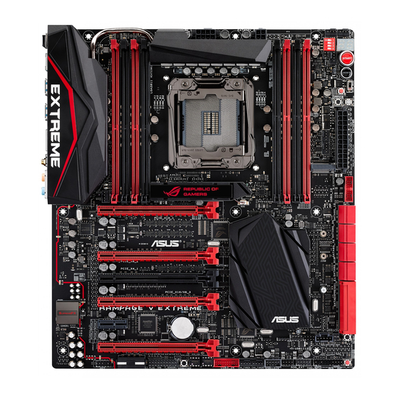
Page 25: Motherboard Overview
Before you install or remove any component, ensure that the ATX power supply is switched off or the power cord is detached from the power supply. Failure to do so may cause severe damage to the motherboard, peripherals, or components. ASUS RAMPAGE V EXTREME... -
Page 26: Motherboard Layout
1.2.2 Motherboard layout Refer to the Internal connectors and the Rear I/O Connection section on Chapter 2 for more information about the internal connectors and rear panel connectors. Chapter 1: Product introduction... -
Page 27: Layout Contents
USB 2.0 connector (10-1 pin USB91112, USB 1314) 1-38 ROG Extension connector (18-1 pin ROG_EXT) 1-36 SOUNDSTAGE button (SOUNDSTAGE) 1-24 TPM connector (20-1 pin TPM) 1-40 Front panel audio connector (10-1 pin AAFP) 1-40 ROG Logo LED connector (3-pin) 1-44 ASUS RAMPAGE V EXTREME... -
Page 28: Central Processing Unit (Cpu)
Contact your retailer immediately if the PnP cap is missing, or if you see any damage to the PnP cap/socket contacts/motherboard components. ASUS will shoulder the cost of repair only if the damage is shipment/ transit-related. -
Page 29: System Memory
The motherboard comes with eight Double Data Rate 4 (DDR4) Dual Inline Memory Module (DIMM) slots. A DDR4 module is notched differently from a DDR3 or DDR2 module. DO NOT install a DDR3 or DDR2 memory module to the DDR4 slot. Recommended memory configurations ASUS RAMPAGE V EXTREME 1-11... -
Page 30: Memory Configurations
Memory configurations You may install 2 GB, 4 GB, and 8 GB unbuffered and non-ECC DDR4 DIMMs into the DIMM sockets. • You may install varying memory sizes in Channel A, Channel B, Channel C, and Channel D. The system maps the total size of the lower-sized channel for the dual- channel configuration. - Page 31 RAMPAGE V EXTREME Motherboard Qualified Vendors List (QVL) DDR4 3300 MHz capability DIMM socket support (Optional) Vendors Part No. Size Chip Brand Chip NO. Timing Voltage G.SKILL F4-3300C17Q-16GRR 16GB(4x4GB) Gskill 17-20-20-44 1.5V • • DDR4 3000 MHz capability DIMM socket...
- Page 32 DDR4 2666 MHz capability DIMM socket support (Optional) Vendors Part No. Size Chip Brand Chip NO. Timing Voltage CORSAIR CMD16GX4M4A2666C14 16GB(4GB*4) 14-16-16-35 1.2V • • CORSAIR CMD32GX4M4A2666C14 32GB(8GB*4) 14-16-16-35 1.2V • • CORSAIR CMK16GX4M4A2666C15 16GB(4GB*4) 15-17-17-35 1.2V • • CORSAIR CMK32GX4M4A2666C15 32GB(8GB*4) 15-17-17-35...
- Page 33 1.2V • • • 17-40 panram PUD42400C154GNJK 15-15- 1.2V • • 15-36 panram PUD42400C158GNJK 15-15- 1.2V • • 15-36 panram PUD42400C154G2NJK 8GB(4GB*2) 15-15- 1.2V • • 15-36 panram PUD42400C158G2NJK 16GB(8GB*2) 15-15- 1.2V • • 15-36 ASUS RAMPAGE V EXTREME 1-15...
- Page 34 DDR4 2133 MHz capability DIMM socket support (Optional) Chip Vendors Part No. Size Chip NO. Timing Voltage Brand Micron MTA8ATF51264AZ- Micron D9RGQ 15-15- 1.2V • • • 2G1A1 15-37 Micron MTA16ATF1G64AZ- Micron D9RGQ 15-15- 1.2V • • • 2G1A1 15-37 Crucial CT4G4DFS8213.8FA1 Micron...
- Page 35 Hyper DIMM support is subject to the physical characteristics of individual CPUs. Load the X.M.P. or D.O.C.P. settings in the BIOS for the hyper DIMM support. • Visit the ASUS website for the latest QVL. ASUS RAMPAGE V EXTREME 1-17...
-
Page 36: Expansion Slots
1.2.5 Expansion slots Ensure to unplug the power cord before adding or removing expansion cards. Failure to do so may cause you physical injury and damage motherboard components. Slot No. Slot Description PCIe 3.0 x16_1 slot PCIe 3.0 x8_2 slot PCIe 2.0 x4_1 slot PCIe 3.0 x16/8_3 slot PCIe 2.0 x1_1 slot... - Page 37 SATAExpress_E1 connector. When the PCIE_X4_1 slot is occupied by an X1 or X2 device, the SATAEXPRESS_E1 will be disabled. When the PCIE_X4_1 slot is occupied by X4 device, both the SATAEXPRESS_E1, USB3_E910 ports, and the PCIE_X1_1 slot will be disabled. ASUS RAMPAGE V EXTREME 1-19...
-
Page 38: Irq Assignments For This Motherboard
IRQ assignments for this motherboard PCIE_X16_1 shared PCIE_X8_2 shared PCIE_x4_1 shared PCIE_X16/X8_3 shared PCIE_X8_4 shared PCIE_X1_1 shared Intel LAN controller shared SATA #0 shared SATA #1 shared HD Audio shared EHCI #0 (USB 2.0) shared EHCI #1 (USB 2.0) shared XHCI (USB 3.0) shared 1-20... -
Page 39: Onboard Buttons And Switches
The button also lights up when the system is plugged to a power source indicating that you should shut down the system and unplug the power cable before removing or installing any motherboard component. Reset button Press the Reset button to reboot the system. ASUS RAMPAGE V EXTREME 1-21... - Page 40 BIOS default settings. A message will appear during POST to remind you that the BIOS has been restored to its default settings. • We recommend that you download and update to the latest BIOS version from www.asus.com after using the MemOK! function. 1-22 Chapter 1: Product introduction...
- Page 41 POST. BIOS Switch button (BIOS_SWITCH) The motherboard comes with two BIOS. Press the BIOS button to switch BIOS and load different BIOS settings. The nearby BIOS LEDs indicate the currently selected BIOS. ASUS RAMPAGE V EXTREME 1-23...
- Page 42 Safe Boot button (SAFE_BOOT) The Safe Boot button can be pressed anytime to force the system to reboot into the BIOS safe mode. This button temporarily applies safe settings to the BIOS while retaining any overclocked settings allowing you to modify the settings causing boot failure. Use this button when overclocking or tweaking the settings of your system.
- Page 43 These slide switches allows you to enable and disable the corresponding PCIe x16 slots. When one of the installed PCIe x16 cards is out of order, you can use the slide switch to find out the faulty one without removing the cards. ASUS RAMPAGE V EXTREME 1-25...
- Page 44 Slow Mode Switch (SLOW_MODE) Slow Mode Switch is employed during LN2 benching. Some processors have a small optimum temperature range to run at their highest frequency. Temperatures that fall outside this band may yield instability. For example, a processor may need to operate at -80°C under load and only 75°C when idle to maintain stability at 5.8GHz.
-
Page 45: Onboard Leds
The BIOS LEDs help indicate the BIOS activity. Press the BIOS button to switch between BIOS1 and BIOS2 and the LED lights up when the corresponding BIOS is in use. PCIE Lane LED indicator Indicates the PCIE lane used. ASUS RAMPAGE V EXTREME 1-27... - Page 46 Q LED Q LEDs check key components (CPU, DRAM, VGA card, and boot devices) in sequence during motherboard booting process. If an error is found, the corresponding LED will continue lighting until the problem is solved. This user-friendly design provides an intuitive way to locate the root-cause of the problem within seconds.
-
Page 47: Q-Code Table
Post-Memory System Agent initialization is started 3B – 3E Post-Memory PCH initialization is started DXE IPL is started Memory initialization error. Invalid memory type or incompatible memory 50 – 53 speed (continued on the next page) ASUS RAMPAGE V EXTREME 1-29... - Page 48 Q-Code table Code Description Unspecified memory initialization error Memory not installed Invalid CPU type or Speed CPU mismatch CPU self test failed or possible CPU cache error CPU micro-code is not found or micro-code update is failed Internal CPU error Reset PPI is not available Reserved for future AMI error codes 5C –...
- Page 49 PCI Bus Hot Plug Controller Initialization PCI Bus Enumeration PCI Bus Request Resources PCI Bus Assign Resources Console Output devices connect Console input devices connect Super IO Initialization USB initialization is started USB Reset (continued on the next page) ASUS RAMPAGE V EXTREME 1-31...
- Page 50 Q-Code table Code Description USB Detect USB Enable Reserved for future AMI codes 9E – 9F IDE initialization is started IDE Reset IDE Detect IDE Enable SCSI initialization is started SCSI Reset SCSI Detect SCSI Enable Setup Verifying Password Start of Setup Reserved for ASL (see ASL Status Codes section below) Setup Input Wait Reserved for ASL (see ASL Status Codes section below)
- Page 51 System is waking up from the S4 sleep state 0x40 System has transitioned into ACPI mode. Interrupt controller is in PIC mode. 0xAC System has transitioned into ACPI mode. Interrupt controller is in APIC mode. 0xAA ASUS RAMPAGE V EXTREME 1-33...
-
Page 52: Jumper
1.2.8 Jumper LN2 Mode jumper (3-pin LN2_MODE) With LN2 mode activated, the ROG motherboard is optimized to remedy the cold-boot bug during POST and help the system boot successfully. 1-34 Chapter 1: Product introduction... -
Page 53: Internal Connectors
ATA RAID array using these connectors, set the SATA Mode item in the BIOS to [RAID Mode]. Refer to the PCH Storage Configuration section for details. • Before creating a RAID array, refer to the RAID configurations section or the manual bundled in the motherboard support DVD. ASUS RAMPAGE V EXTREME 1-35... - Page 54 ASMedia Serial ATA 6 Gb/s connectors (7-pin SATA6G_E3E4; SATAEXPRESS_E1) ® These connectors connect to Serial ATA 6 Gb/s hard disk drives via Serial ATA 6 Gb/s signal cables. • The ASMedia storage controller can only support AHCI mode. • These SATA ports are for data drives only. •...
- Page 55 USB 3.0 solution. • The USB 3.0 module is purchased separately. • These connectors are based on xHCI specification. We recommend you to install the related driver to fully use the USB 3.0 ports under Windows ® ASUS RAMPAGE V EXTREME 1-37...
- Page 56 Never connect a 1394 cable to the USB connectors. Doing so will damage the motherboard! You can connect the front panel USB cable to the ASUS Q-Connector (USB) first, and then install the Q-Connector (USB) to the USB connector onboard if your chassis supports front panel USB ports.
- Page 57 Do not forget to connect the fan cables to the fan connectors. Insufficient air flow inside the system may damage the motherboard components. These are not jumpers! Do not place jumper caps on the fan connectors! The CPU_FAN connector supports the CPU fan of maximum 1A (12 W) fan power. ASUS RAMPAGE V EXTREME 1-39...
- Page 58 Front panel audio connector (10-1 pin AAFP) This connector is for a chassis-mounted front panel audio I/O module that supports either HD Audio or legacy AC`97 audio standard. Connect one end of the front panel audio I/O module cable to this connector. •...
- Page 59 The M.2 (Socket 3) with M Key supports type 2260 (22 mm x 60 mm), 2280 (22 mm x 80 mm), and 22110 (22 mm x 110 mm) PCIe interface storage devices. The PCIE_X8_4 slot shares bandwidth with M.2 x4. When PCIE_X8_4 is occupied, the M.2 will be disabled. ASUS RAMPAGE V EXTREME 1-41...
- Page 60 ATX power connectors (24-pin EATXPWR; 4-pin EATX12V_1; 8-pin EATX12V_2; 4-pin EZ_PLUG) These connectors are for ATX power supply plugs. The power supply plugs are designed to fit these connectors in only one orientation. Find the proper orientation and push down firmly until the connectors completely fit. •...
-
Page 61: System Panel Connector
ON turns the system OFF. • Reset button (2-pin RESET) This 2-pin connector is for the chassis-mounted reset button for system reboot without turning off the system power. ASUS RAMPAGE V EXTREME 1-43... - Page 62 ROG Logo LED connector (3-pin ROG) This connector is for the box (labelled Republic of Gamers) below the CPU socket. Connect the box’s cable to this connector. The box lights up when you turn on the system. 1-44 Chapter 1: Product introduction...
-
Page 63: Probeit
Using ProbeIt You can connect the multimeter to the motherboard as shown on the following figure. The illustration above are for reference only, the actual motherboard layout and measure points location may differ by models. ASUS RAMPAGE V EXTREME 1-45... - Page 64 1-46 Chapter 1: Product introduction...
-
Page 65: Chapter 2: Basic Installation
The diagrams in this section are for reference only. The motherboard layout may vary with models, but the installation steps are the same for all models. Install the ASUS Q-Shield to the chassis rear I/O panel. Place the motherboard into the chassis ensuring that its rear I/O ports are aligned to the chassis’... - Page 66 Place nine screws into the holes indicated by circles to secure the motherboard to the chassis. DO NOT overtighten the screws! Doing so can damage the motherboard. Chapter 2: Basic Installation...
-
Page 67: Cpu Installation
2.1.2 CPU installation Ensure that you install the correct CPU designed for LGA2011-v3 socket only. DO NOT install a CPU designed for LGA1150, LGA1155, and LGA1156 sockets on the LGA2011-v3 socket. Triangle mark Load lever ASUS RAMPAGE V EXTREME... - Page 68 Triangle mark edge of the Load plate Load plate PnP cap Chapter 2: Basic Installation...
-
Page 69: Cpu Heatsink And Fan Assembly Installation
2.1.3 CPU heatsink and fan assembly installation Apply the thermal interface material to the CPU heatsink and CPU before you install the heatsink and fan, if necessary. Installing the CPU heatsink and fan assembly ASUS RAMPAGE V EXTREME... - Page 70 Uninstalling the CPU heatsink and fan assembly Chapter 2: Basic Installation...
- Page 71 Replacing the LGA2011-v3 CPU pad (X-Socket 2) The X-Socket 2 is a unique ROG feature that allows the user to use their LN2 pot on the LGA 2011-v3 motherboard. ASUS RAMPAGE V EXTREME...
-
Page 72: Dimm Installation
2.1.4 DIMM installation To remove a DIMM Chapter 2: Basic Installation... -
Page 73: Atx Power Connection
2.1.5 ATX Power connection ASUS RAMPAGE V EXTREME... -
Page 74: Sata Device Connection
2.1.6 SATA device connection 2-10 Chapter 2: Basic Installation... -
Page 75: Front I/O Connector
2.1.7 Front I/O Connector Installing the ASUS Q-Connector Installing the USB 2.0 connector Installing the front panel audio connector AAFP USB 2.0 Installing the USB 3.0 connector USB 3.0 ASUS RAMPAGE V EXTREME 2-11... -
Page 76: Expansion Card Installation
2.1.8 Expansion Card installation Installing the PCIe x16 cards Installing the PCIe x1 cards 2-12 Chapter 2: Basic Installation... -
Page 77: Wi-Fi Antenna Installation
Wi-Fi antenna installation Installing the ASUS 3T3R dual band Wi-Fi antenna To install the ASUS 3T3R dual band Wi-Fi antenna, connect the bundled ASUS 3T3R dual band Wi-Fi antenna connector to the Wi-Fi ports at the back of the chassis. -
Page 78: Bios Update Utility
USB BIOS Flashback/ ROG Connect port For more BIOS update utilities in BIOS setup, refer to the Updating BIOS section in Chapter 3. • DO NOT unplug portable disk, power system, or press the CLR_CMOS button while the BIOS update is ongoing, otherwise the update will be interrupted. In case of interruption, please follow the steps again. • Updating the BIOS may have risks. If the BIOS program is damaged during the process and results in the system’s failure to boot up, please contact your local ASUS Service Center. 2-14 Chapter 2: Basic Installation... -
Page 79: Motherboard Rear And Audio Connections
10. Audio I/O ports with Optical S/PDIF Out port*** *, **, and ***: Refer to the tables on the next page for Bluetooth/Wi-Fi module LEDs, LAN port LEDs, and audio port definitions. The PCIE_X4_1 (gray) slot shares bandwidth with the PCIE_X1_1 slot, USB3_E910, and SATAExpress_E1 connector. When the PCIE_X4_1 slot is occupied by an X1 or X2 device, the SATAEXPRESS_E1 will be disabled. When the PCIE_X4_1 slot is occupied by X4 device, both the SATAEXPRESS_E1, USB3_E910 ports, and the PCIE_X1_1 slot will be disabled. ASUS RAMPAGE V EXTREME 2-15... - Page 80 • We strongly recommend that you connect USB 3.0 devices to USB 3.0 ports for faster and better performance for your USB 3.0 devices. • When using the external SATA port, ensure to use a compatible connector. * LAN ports LED indications Activity Link LED Speed LED Status Description Status Description ACT/LINK SPEED No link 10 Mbps connection Orange Linked Orange 100 Mbps connection Orange (Blinking) Data activity Green 1 Gbps connection Orange (Blinking Ready to wake up LAN port then steady) from S5 mode...
-
Page 81: Audio I/O Connections
2.3.2 Audio I/O connections Audio I/O ports Connect to Headphone and Mic Connect to Stereo Speakers Connect to 2.1 channel Speakers ASUS RAMPAGE V EXTREME 2-17... - Page 82 Connect to 4.1 channel Speakers Connect to 5.1 channel Speakers Connect to 7.1 channel Speakers 2-18 Chapter 2: Basic Installation...
-
Page 83: Oc Panel
Value up Button OK button Right Arrow button Left Arrow button Clear button Reset button Value Down button Fan connectors 1,2 Fan connectors 3,4 VGA hotwire connectors Pause and Slow Mode VGA hotwire OC Panel cover ASUS RAMPAGE V EXTREME 2-19... - Page 84 OC Panel LCM Display in Normal Mode OC Panel LCM Display in Extreme Mode Extreme Mode capabilities including V1, V2, DRAM, and other voltage definitions vary by chipset. Please refer to your motherboard manual for details. 2-20 Chapter 2: Basic Installation...
-
Page 85: Setting Up Your Oc Panel In Normal Mode
Prepare the bundled OC Panel 5.25-inch drive bay metal case and set of two (2) screws. Align and insert the OC Panel into the OC Panel 5.25-inch drive bay metal case. OC Panel fits in one orientation only. If it does not fit, try reversing it. ASUS RAMPAGE V EXTREME 2-21... - Page 86 Secure the OC Panel to the OC Panel 5.25-inch drive bay metal case with the two (2) screws. Ensure that the OC Panel fits snugly into the OC Panel 5.25-inch drive bay metal case. Shut down your computer. Open your computer chassis and remove the front cover of an available 5.25-inch drive bay.
-
Page 87: Setting Up Your Oc Panel In Extreme Mode
Extreme Mode capabilities including V1, V2, DRAM, and other voltage definitions vary by chipset. Please refer to your motherboard manual for details. To setup the OC Panel in Extreme Mode: Shut down your computer. Connect the OC Panel cable (A) and a SATA Power cable (B) to the OC Panel. Locate the ROG_EXT connector on the motherboard and connect the OC Panel cable. Boot your computer. Press the OC Panel power button to turn on the OC Panel LCM display. ASUS RAMPAGE V EXTREME 2-23... -
Page 88: Starting Up For The First Time
Starting up for the first time After making all the connections, replace the system case cover. Ensure that all switches are off. Connect the power cord to the power connector at the back of the system chassis. Connect the power cord to a power outlet that is equipped with a surge protector. Turn on the devices in the following order: a. Monitor b. External SCSI devices (starting with the last device on the chain) -
Page 89: Chapter 3: Bios Setup
BIOS setup Knowing BIOS The new ASUS UEFI BIOS is a Unified Extensible Interface that complies with UEFI architecture, offering a user-friendly interface that goes beyond the traditional keyboard- only BIOS controls to enable a more flexible and convenient mouse input. You can easily navigate the new UEFI BIOS with the same smoothness as your operating system. -
Page 90: Bios Setup Program
BIOS setup program Use the BIOS Setup to update the BIOS or configure its parameters. The BIOS screen includes navigation keys and a brief on-screen tip to help guide you in using the BIOS Setup program. Entering BIOS at startup To enter BIOS Setup at startup, press <Delete>... -
Page 91: Ez Mode
Selects the boot device priority • The boot device options vary depending on the devices you installed to the system. • The Boot Menu (F8) button is available only when a boot device is installed to the system. ASUS RAMPAGE V EXTREME... -
Page 92: Advanced Mode
3.2.2 Advanced Mode Advanced Mode provides advanced options for experienced end-users to configure the BIOS settings. The figure below shows an example of Advanced Mode. Refer to the following sections for the detailed configurations. To access the Advanced Mode, click Exit, then select Advanced Mode or press F7 hotkey. Quick Note (F9) Pop-up Menu Configuration fields... -
Page 93: Menu Items
The Quick Note function does not support the following keyboard functions: delete, cut, copy, and paste. • You can only use the alphanumeric characters to enter your notes. Last Modified button This button shows the items that you last modified and saved in BIOS Setup. ASUS RAMPAGE V EXTREME... -
Page 94: My Favorites
My Favorites My Favorites is your personal space where you can easily save and access your favorite BIOS items. Adding items to My Favorites To add frequently-used BIOS items to My Favorites: Use the arrow keys to select an item that you want to add. When using a mouse, hover the pointer to the item. -
Page 95: Main Menu
RAM to clear the BIOS password. See the section about Rear I/O Connection in Chapter 2 for more information. • The Administrator or User Password items on top of the screen show the default [Not Installed]. After you set a password, these items will be displayed as [Installed]. ASUS RAMPAGE V EXTREME... -
Page 96: Administrator Password
Administrator Password If you have set an administrator password, we recommend that you enter the administrator password when accessing the system. Otherwise, you may be restricted from viewing or modifying certain fields in the BIOS Setup program. To set an administrator password: Select the Administrator Password item and press <Enter>. -
Page 97: Extreme Tweaker Menu
Be cautious when changing the settings of the Extreme Tweaker menu items. Incorrect field values can cause the system to malfunction. The configuration options for this section vary depending on the CPU and DIMM model you installed on the motherboard. Scroll down to display other BIOS items. ASUS RAMPAGE V EXTREME... - Page 98 The [X.M.P.] configuration option appears only when you install memory modules supporting the eXtreme Memory Profile (X.M.P.) Technology. ASUS MultiCore Enhancement [Auto] Allows you to enable or disable the MultiCore Enhancement feature. Configuration options: [Disabled] [Auto] CPU Core Ratio [Auto] Allows you to set the CPU ratio and sync automatically, per core or all cores.
- Page 99 The BCLK frequency to DRAM frequency is set to the optimized settings. [100:133] The BCLK frequency to DRAM frequency ratio is set to 100:133. [100:100] The BCLK frequency to DRAM frequency ratio is set to 100:100. ASUS RAMPAGE V EXTREME 3-11...
- Page 100 DRAM Frequency [Auto] Allows you to set the memory operating frequency. The configuration options vary with the BCLK/CPU Strap Frequency item settings. Xtreme Tweaking [Disabled] Helps improve benchmark performance. Configuration options: [Disabled] [Enabled] CPU Level Up [Auto] Allows you to overclock the CPU at a certain frequency. Configuration options: [Auto] [4.4000G] [4.2000G] [4.0000G] EPU Power Saving Mode [Disabled] Allows you to enable or disable the EPU power saving function.
-
Page 101: Dram Timing Control
Configuration options: [Auto] [1] – [31] DRAM RAS# PRE Time [Auto] Configuration options: [Auto] [1] – [15] DRAM RAS# ACT Time [Auto] Configuration options: [Auto] [1] – [63] DRAM Command Rate [Auto] Configuration options: [Auto] [1] – [3] ASUS RAMPAGE V EXTREME 3-13... - Page 102 Secondary Timings DRAM RAS# to RAS# Delay [Auto] Configuration options: [Auto] [1] – [7] DRAM RAS# to RAS# Delay [Auto] Configuration options: [Auto] [1] – [7] DRAM REF Cycle Time [Auto] Configuration options: [Auto] [1] – [511] DRAM Refresh Interval [Auto] Configuration options: [Auto] [1] –...
- Page 103 [Auto] Configuration options: [Auto] [0 DRAM Clock] – [7 DRAM Clock] tCCDWR [Auto] Configuration options: [Auto] [0 DRAM Clock] – [7 DRAM Clock] tCCD_L [Auto] Configuration options: [Auto] [0 DRAM Clock] – [7 DRAM Clock] ASUS RAMPAGE V EXTREME 3-15...
- Page 104 RTL IOL control DRAM RTL INIT Value [Auto] Configuration options: [Auto] [1] - [127] DRAM RTL (CHA D0 R0) [Auto] Configuration options: [Auto] [1] - [127] DRAM RTL (CHA D0 R1) [Auto] Configuration options: [Auto] [1] - [127] DRAM RTL (CHA D1 R0) [Auto] Configuration options: [Auto] [1] - [127] DRAM RTL (CHA D1 R1) [Auto] Configuration options: [Auto] [1] - [127]...
- Page 105 Configuration options: [Auto] [60] - [99] DRAM Vref (CHD) [Auto] Configuration options: [Auto] [60] - [99] CTL Vref (CHAB) Sign [+] Configuration options: [+] [-] CTL Vref (CHAB) [Auto] Configuration options: [Auto] [0.00] - [0.20] ASUS RAMPAGE V EXTREME 3-17...
- Page 106 CTL Vref (CHCD) Sign [+] Configuration options: [+] [-] CTL Vref (CHCD) [Auto] Configuration options: [Auto] [0.00] - [0.20] Receiver DQ Pre-emphasis [Auto] Configuration options: [Auto] [0.90] - [1.60] Receiver DQ De-emphasis [Auto] Configuration options: [Auto] [0.90] - [1.60] Transmitter DQ Pre-emphasis [Auto] Configuration options: [Auto] [0.90] - [1.60] Receiver DQS Pre-emphasis [Auto] Configuration options: [Auto] [0.90] - [1.60]...
- Page 107 Configuration options: [Auto] [Enabled] [Disabled] MemTest [Disabled] Configuration options: [Auto] [Enabled] [Disabled] Attempt Fast Boot [Auto] Configuration options: [Auto] [Enabled] [Disabled] DRAM Training [Auto] Configuration options: [Auto] [Enabled] [Disabled] MemTest on Fast Boot [Disabled] Configuration options: [Auto] [Enabled] [Disabled] ASUS RAMPAGE V EXTREME 3-19...
- Page 108 External DIGI+ Power Control Some of the following items are adjusted by typing the desired values using the numeric keypad and press the <Enter> key. You can also use the <+> and <-> keys to adjust the value. To restore the default setting, type [auto] using the keyboard and press the <Enter> key.
- Page 109 DRAM Power Phase Control (CHA, CHB)/ CHC, CHD) [Optimized] Allows you to enable or disable the DRAM CD settings. [Optimized] Set to the optimized ASUS phase tuning profile. [Standard] The phase control will be based on the CPU command. [Extreme] Set to the full phase mode.
- Page 110 Tweaker’s Paradise BCLK Amplitude [Auto] This item allows you to adjust the magnitude of the BCLK. Configuration options: [Auto] [Lower] [Normal] [Higher] ICC Ringback Canceller [Disabled] Allows you to enable the ICC Ringback Canceller. Configuration options: [Auto] [Enabled] [Disabled] Cross-Talk Cancellation Voltage [Disabled] Configuration options: [Auto] [Enabled] [Disabled] ICC Ringback Canceller [Auto] Allows you to enable the ICC Ringback Canceller.
- Page 111 Configuration options: [1] - [4095] According to Intel, the platfrom must be capabale of supporting the duration for up to 10 msec. when the turbo ratio exceeds the power limit 2. ASUS motherboards can support the duration for longer time.
- Page 112 CPU Core Voltage [Auto] This item allows you to configure the amount of voltage fed to the CPU cores. Increase the voltage when configuring a high CPU core frequency. Configuration options: [Auto] [Manual Mode] [Offset Mode] [Adaptive Mode] The following item appears only when you set the CPU Core Voltage to [Manual Mode]. CPU Core Voltage Override [Auto] This item allows you to configure the CPU core voltage.
- Page 113 CPU core frequency. The voltage you set is affected by the offset value. Use the <+> or <-> keys to adjust the value. The values range from 0.001V to 1.920 V with a 0.001 V interval. ASUS RAMPAGE V EXTREME 3-25...
- Page 114 CPU System Agent Voltage Offset Mode Sign [+] To offset the voltage by a positive value. [–] To offset the voltage by a negative value. CPU System Agent Voltage Offset [Auto] This item allows you to set the amount of voltage fed to the system agent of the processor including its PCIE controller and power control unit (PCU).
- Page 115 (electromagnetic disturbance) generated by the BCLK. Set this item to [Enabled] for EMI reduction, or set this item to [Disabled] to enhance BCLK overclocking. Configuration options: [Auto] [Disabled] [Enabled] BCLK Recovery [Enabled] This item allows you to enable or disable BCLK Recovery. Configuration options: [Disabled] [Enabled] [Ignore] ASUS RAMPAGE V EXTREME 3-27...
-
Page 116: Advanced Menu
Advanced menu The items in Advanced menu allow you to change the settings of the CPU and other system devices. Be cautious when changing the settings of the items in Advanced menu. Incorrect field values can cause the system to malfunction. 3-28 Chapter 3: BIOS setup... -
Page 117: Cpu Configuration
Configuration options: [Disabled] [Enabled] Execute Disable Bit [Enabled] Execute Disable prevents certain classes of malicious buffer overflow attacks when combined with a supporting OS (SuSE Linux 9.2, RedHat Enterprise 3 Update 3). Configuration options: [Disabled] [Enabled] ASUS RAMPAGE V EXTREME 3-29... - Page 118 Intel Virtualization Technology [Disabled] When set to [Enabled], a VMM can utilize the additional hardware capabilities provided by Vanderpool Technology. Configuration options: [Disabled] [Enabled] Hardware Prefetcher [Enabled] This item allows the CPU to prefetch commands and data in the L2 cache, reducing the DRAM loading time and improving system performance.
- Page 119 Configuration options: [Enabled] [Disabled] Package C State Support [Auto] This item allows you to set the a C-state support for the CPU package. Configuration options: [Auto] [C0/C1 state] [C2 state] [C6(non Retention) state] [C6(Retention) state] ASUS RAMPAGE V EXTREME 3-31...
-
Page 120: Pch Configuration
3.6.2 PCH Configuration PCI Express Configuration This item allows you to configure the PCI Express slots. PCI-E Speed [Auto] This item allows your system to automatically select the PCI Express port speed. When set to [Gen1], the PCI-E port runs at PCI-E 1.0 speed. When set to [Gen2], the PCI-E port runs at PCI-E 2.0 speed. -
Page 121: Pch Storage Configuration
While entering Setup, the BIOS automatically detects the presence of SATA devices. The SATA Port items show Empty if no SATA device is installed to the corresponding SATA port. Scroll down to display the other BIOS items. ASUS RAMPAGE V EXTREME 3-33... - Page 122 The system automatically adjusts the SRIS support for connected SATAEXPRESS devices. [Disabled] Select this option for ASUS RUNWAY SATA Express bridge card. S.M.A.R.T. Status Check [On] S.M.A.R.T. (Self-Monitoring, Analysis and Reporting Technology) is a monitoring system that shows a warning message during POST (Power-on Self Test) when an error occurs in the hard disks.
-
Page 123: System Agent Configuration
Intel VT for Directed I/O (VT-d) [Disabled] This item allows you to enable/disable the Intel Virtualization Technology for Directed I/O (VT-d) by reporting the I/O device assigment to VMM through DMAR ACPI Tables. Configuration options: [Enabled] [Disabled] ASUS RAMPAGE V EXTREME 3-35... -
Page 124: Usb Configuration
3.6.5 USB Configuration The items in this menu allow you to change the USB-related features. The USB Devices item shows the auto-detected values. If no USB device is detected, the item shows None. Intel xHCI Mode [Smart Auto] [Smart Auto] Once the xHCI driver has been detected, the USB 3.0 mode will be supported during both POST and operating system. - Page 125 Support for EHCI using the BIOS for operating systems without EHCI support. USB Single Port Control [Disabled] Allows you to enable or disable the individual USB ports. Configuration options: [Enabled] [Disabled] Refer to the Motherboard layout section for the location of the USB ports. ASUS RAMPAGE V EXTREME 3-37...
-
Page 126: Platform Miscellaneous Configuration
3.6.6 Platform Miscellaneous Configuration SA DMI ASPM [Disabled] Allows you to enable or disable the ASPM (L1) support for the downstream devices. Configuration options: [Auto] [Disabled] [L1 only] PEG ASPM Support [Disabled] Allows you to enable or disable the ASPM support for all downstream devices. Configuration options: [Disabled] [L1 only] PCH DMI ASPM [Disabled] Allows you to enable or disable the PCH DMI ASPM setting. -
Page 127: Onboard Devices Configuration
PCI-E mode first then on SATA mode. The SATA devices are available when no PCIEx8_4 or M.2 devices are installed. Configuration options: [Auto] [M.2] ASMedia USB 3.0 Controller [Enabled] This item allows you to enable the ASMedia USB 3.0 controller of your system. ® Configuration options: [Disabled] [Enabled] ASUS RAMPAGE V EXTREME 3-39... - Page 128 [Auto] The system automatically adjusts the SRIS support for connected SATAEXPRESS devices. [Disabled] Select this option for ASUS RUNWAY SATA Express bridge card. Bluetooth Controller [Enabled] Allows you to enable or disable the Bluetooth controller. Configuration options: [Enabled] [Disabled] Wi-Fi Controller [Enabled] Allows you to enable or disable the Wi-Fi controller.
-
Page 129: Apm
PCIE LAN devices. Power On By RTC [Disabled] [Disabled] Prevents the RTC from generating a wake event. [Enabled] When set to [Enabled], the items RTC Alarm Date (Days) and Hour/ Minute/Second will become user-configurable with set values. ASUS RAMPAGE V EXTREME 3-41... -
Page 130: Network Stack Configuration
3.6.9 Network Stack Configuration Network Stack [Disabled] This item allows you to disable or enable the UEFI network stack. Configuration options: [Disabled] [Enabled] The following items appear only when you set the Network Stack to [Enabled]. Ipv4 / Ipv6 PXE Support [Enabled] Allows you to enable or disable the Ipv4/Ipv6 PXE boot option. -
Page 131: Monitor Menu
Press <Enter> and select [Ignore] if you do not wish to display the detected temperatures. Qfan Tuning Click this item to automatically detect the lowest speed and configure the minimum duty cycle for each fan. ASUS RAMPAGE V EXTREME 3-43... - Page 132 CPU Q-Fan Control [Auto] Allows you to set the CPU Q-Fan operating mode. [Disabled] Disables the CPU Q-Fan control feature. [Auto] Detects the type of CPU fan installed and automatically switches the mode control. When a 3-pin CPU fan is installed, select this mode for the DC mode Q-Fan control.
- Page 133 A/B Profile, Chassis Fan 3 A/B Profile to [Manual]. Chassis Fan 1/2/3 Upper Temperature [70] Use the <+> or <-> keys to adjust the upper limit of the CPU temperature. The values range from 20°C to 75°C. ASUS RAMPAGE V EXTREME 3-45...
- Page 134 Chassis Fan 1/2/3 Max. Duty Cycle (%) [100] Use the <+> or <-> keys to adjust the maximum CPU fan duty cycle. The values range from 20% to 100%. When the CPU temperature reaches the upper limit, the CPU fan will operate at the maximum duty cycle.
-
Page 135: Boot Menu
All devices connected to SATA ports will be available during POST. [Hard Drive Only] Only hard drives connected to SATA ports will be detected during POST. [Boot Drive Only] Only boot drive connected to SATA ports will be detected during POST. ASUS RAMPAGE V EXTREME 3-47... - Page 136 USB Support [Partial Initialization] [Disabled] All USB devices will not be available until OS boot up for a fastest POST time. [Full Initialization] All USB devices will be available during POST. This process will extend the POST time. [Partial For a faster POST time, only USB ports with keyboard and Initialization] mouse connections will be detected.
- Page 137 The following items appear when you set the Launch CSM to [Enabled]. Boot Device Control [UEFI and Legacy] This item allows you to select the type of devices that you want to boot. Configuration options: [UEFI and Legacy] [Legacy OpROM only] [UEFI only] ASUS RAMPAGE V EXTREME 3-49...
-
Page 138: Secure Boot Menu
Boot from Network Devices [Legacy OpROM first] This item allows you to select the type of network devices that you want to launch. Configuration options: [Ignore] [Legacy OpROM first] [UEFI driver first] Boot from Storage Devices [Legacy OpROM first] This item allows you to select the type of storage devices that you want to launch. Configuration options: [Both, Legacy OpROM first] [Both, UEFI first] [Legacy OpROM first] [UEFI driver first] [Ignore] Boot from PCI-E/PCI Expansion Devices [Legacy OpROM first]... - Page 139 This item allows you to load the downloaded DB from a USB storage device. Append db from File This item allows you to load the additional DB from a storage device so that more images can be loaded securely. ASUS RAMPAGE V EXTREME 3-51...
-
Page 140: Boot Option Priorities
® ® supported). • To select the boot device during system startup, press <F8> when ASUS Logo appears. Boot Override These item displays the available devices. The number of device items that appear on the screen depends on the number of devices installed in the system. Click an item to start booting from the selected device. -
Page 141: Tool Menu
This function allows you to enable the GPU Post feature. ASUS EZ Flash 2 Utility Allows you to run ASUS EZ Flash 2. When you press <Enter>, a confirmation message appears. Use the left/right arrow key to select between [Yes] or [No], then press <Enter> to confirm your choice. -
Page 142: Asus Overclocking Profile
Select [Yes] to force the boot using BIOS2. COPY BIOS1/BIOS2 to BIOS2/BIOS1 Select [Yes] to copy the content of BIOS1 to BIOS2. ASUS DRAM SPD Information This item allows you to view the DRAM SPD information. DIMM Slot Number Allows you to view the information about the installed DIMMS when selected. -
Page 143: Exit Menu
<Esc>, a confirmation window appears. Select Yes to discard changes and exit. Launch EFI Shell from USB drives This option allows you to attempt to launch the EFI Shell application (shellx64.efi) from one of the available filesystem devices. ASUS RAMPAGE V EXTREME 3-55... -
Page 144: Updating Bios
Inappropriate BIOS updating may result in the system’s failure to boot. Carefully follow the instructions of this chapter to update your BIOS if necessary. Visit the ASUS website at www.asus.com to download the latest BIOS file for this motherboard. The following utilities allow you to manage and update the motherboard BIOS setup program. -
Page 145: Asus Ez Flash 2
3.11.2 ASUS EZ Flash 2 ASUS EZ Flash 2 allows you to update the BIOS without having to use a bootable floppy disk or an OS-based utility. Before you start using this utility, download the latest BIOS from the ASUS website at www.asus.com. -
Page 146: Asus Crashfree Bios 3
The BIOS file in the motherboard support DVD may be older than the BIOS file published on the ASUS official website. If you want to use the newer BIOS file, download the file at support.asus.com and save it to a USB flash drive. -
Page 147: Asus Bios Updater
3.11.4 ASUS BIOS Updater The ASUS BIOS Updater allows you to update the BIOS in DOS environment. This utility also allows you to copy the current BIOS file so that you can use it as a backup when the BIOS fails or gets corrupted during the update process. - Page 148 On the BIOS Updater screen, press <Tab> to switch from Files panel to Drives panel then select D:. ASUSTek BIOS Updater for DOS V1.30 [2012/05/22] FLASH TYPE: MX1C 25L1065A Current ROM Update ROM BOARD: RAMPAGE V EXTREME BOARD: UNKNOWN VER: 0106 VER: UNKNOWN DATE:...
- Page 149 DO NOT shut down or reset the system while updating the BIOS to prevent system boot failure. Ensure to load the BIOS default settings to ensure system compatibility and stability. Select Load Optimized Defaults item under the Exit BIOS menu. See section 3.10 Exit menu for details. ASUS RAMPAGE V EXTREME 3-61...
- Page 150 3-62 Chapter 3: BIOS setup...
-
Page 151: Chapter 4: Software Support
• Motherboard settings and hardware options vary. Use the setup procedures presented in this chapter for reference only. Refer to your OS documentation for detailed information. Support DVD information The contents of the support DVD are subject to change at any time without notice. Visit the ASUS website at www.asus.com for updates. 4.2.1 Running the support DVD Ensure that you have an Administrator account before running the support DVD in Windows 7 or Windows 8/ Windows 8.1 OS. ® ® ® To run the support DVD Place the Support DVD into the optical drive. 2. In the AutoPlay dialog box, click Run ASSETUP.exe. If the AutoPlay dialog box does not appear, browse the contents of the support DVD and ASUS motherboard support double-click or tap \\bin\ASSETUP.EXE to launch the DVD main menu ASUS RAMPAGE V EXTREME... - Page 152 Click or tap an icon to display DVD/motherboard information Click to launch InstAll installation wizard Click or tap an item to install Drivers menu Click to display the available device drivers for system-detected devices. Install the necessary drivers to use for the installed devices. Utilities menu Click to display the list of applications and other software that the motherboard supports. Manual menu Click to see the list of supplementary user manuals. Click an item to open the folder of the user manual. Video menu Click to see ROG product related videos. Contact menu Click to display the ASUS contact information. Specials menu Click to see ASUS related product information. Chapter 4: Software support...
-
Page 153: Obtaining The Software Manuals
4.2.2 Obtaining the software manuals The software manuals are included in the support DVD. Follow the instructions below to get the necessary software manuals. The software manual files are in Portable Document Format (PDF). Install the Adobe ® Acrobat Reader from the Utilities tab before opening the files. ® To read about your motherboard’s utility guide: Click or tap Manual tab > ASUS Motherboard Utility Guide. From the Manual folder, open the folder of the software manual that you wish to read. Some software manuals are provided in different languages. Open the language’s folder to view the software manual. The screenshots in this section are for reference only. The actual software manuals containing in the support DVD vary by models. ASUS RAMPAGE V EXTREME... -
Page 154: Software Information
Installing AI Suite 3 • Ensure that you have an Administrator account before installing AI Suite 3 in Windows 7 or Windows 8 / Windows 8.1 OS. ® ® ® • To install the Wi-Fi-enabled features of AI Suite 3, ensure that you install the Wi-Fi module and its latest driver from the bundled support DVD. To do this, go to Drivers tab > ASUS Bluetooth 4.0 Wi-Fi Driver and follow the succeeding onscreen instructions. To install AI Suite 3 on your computer: Windows 7 OS ® Place the Support DVD into the optical drive. 2. In the AutoPlay dialog box, click Run ASSETUP.exe then select the Utilities tab. 3. From the Utilities tab, click AI Suite 3 then follow the succeeding onscreen instructions. Chapter 4: Software support... - Page 155 If the ASUS motherboard support DVD main menu did not appear, try the following steps: Go to the Start Screen then click or tap the Desktop app. On the lower left corner of the Desktop, click or tap File Explorer then select your DVD drive and tap or double-click the Setup application. Launching AI Suite 3 Windows 7 OS ® From the Desktop, click Start > All Programs > ASUS > AI Suite 3 > AI Suite 3. You can also launch AI Suite 3 in Windows 7 by clicking on the Notification area. ® Windows 8 / Windows 8.1 OS ® ®...
- Page 156 AI Suite 3 Main menu The AI Suite 3 main menu gives you easy-access controls and insight to what’s going on with your computer - allowing you to optimize performance settings while at the same time ensuring system stability. The AI Suite main menu includes is a quick-access menu bar that allows you to swiftly launch any of the integrated ASUS utilities. Click or tap on the top-right corner of the menu to launch the menu bar. The AI Suite 3 screenshots in this section are for reference only and can vary depending on motherboard model. Click or tap to launch AI Suite 3 menu bar AI Suite 3 main menu bar USB BIOS EZ Update 5-Way Optimization Ai Charger+ Wi-Fi Engine Flashback USB 3.0 Boost...
-
Page 157: Dual Intelligent Processors 5
Dual Intelligent Processors 5 ASUS Dual Intelligent Processors 5 combines TPU, EPU, DIGI+ Power Control, Fan Xpert 3, and Turbo App functions to push the system’s performance to its optimal potential. It automatically balances the system’s performance, power saving, levels, and fan settings via the user-friendly AI Suite 3 utility. 5-Way Optimization The 5-Way Optimization function dynamically optimizes your PC based on real-time usage to provide the best system status. It covers the essential areas such as CPU performance, energy saving, stable digital power, cool and quiet fan control, and includes tailored settings for your apps to ensure your PC is ready for gaming, entertainment, productivity, or just about anything. Click or tap this 5-Way Optimization button to auto-detect and tune the best settings for your system DO NOT remove your fan during the tuning process. ASUS RAMPAGE V EXTREME... -
Page 158: Turbo Processing Unit (Tpu)
Turbo Processing Unit (TPU) TPU allows you to manually adjust the CPU frequency, CPU cache, core frequencies, DRAM frequency, and related voltages for enhanced system stability and a performance boost. Refer to the CPU documentation before adjusting CPU voltage settings. Setting a high voltage may damage the CPU permanently and setting a low voltage may lead to an unstable system. For system stability, the TPU settings are not saved in the BIOS and are not loaded during system bootup. Save your overclocking settings as a TPU profile and manually load this profile after system bootup. Using TPU CPU Frequency Click or tap to select the Tick to enable Click or tap or move the sliders number of cores to adjust Group Tuning to adjust the BCLK Frequency, Ratio, and CPU Cache Ratio Scroll down to view other items... - Page 159 Click to undo the Click or tap to apply Click or tap to load adjustments the default settings the saved profile Click or tap to save the adjustment into a profile Click or tap to apply the adjustments ASUS RAMPAGE V EXTREME...
-
Page 160: Fan Xpert 3
Fan Xpert 3 ASUS Fan Xpert 3 provides customizable settings of your fans for a cooler and quieter computing environment. With its automatic fan tuning feature, ASUS Fan Xpert 3 automatically tweaks the settings of CPU and chassis fans to create the best cooling profiles. ASUS Fan Xpert 3 also supports hardware level PWM/DC combo mode for the CPU and chassis fans. You can also reduce the CPU fan speed below the default minimum for a noiseless operation during light loads. Click or tap a screen to select the type of fan that you want to customize Click or tap to Click or tap to set maximize the the fan’s speed to... -
Page 161: Digi+ Power Control
VRM Phase Control Increase the number of active phases under a heavy system load to get better transient and thermal performance. Reduce the number of active phases under a light system load to increase efficiency. VRM Frequency Enables spread spectrum to enhance system stability. CPU OTP Capability Increase the CPU’s maximum operating temperature to extend the overclocking tolerance to increase overclocking potential. Vcore Current Capability Vcore Current Capability allows users to control the total power range for overclocking. A higher value correlates to a wider total power range and extends the overclocking frequency range. Vcore Load-line Calibration Vcore Load-line Calibration adjusts the voltage range of the CPU load-line. Increase the value for better performance and decrease the value for better efficiency. VRM Duty Control VRM Duty Control adjusts the operating current and thermal condition of each phase component. Active Frequency Mode Active Frequency Mode allows you to enhance the power saving condition of the CPU. Tick ON to get a quicker transient response while saving the CPU power. ASUS RAMPAGE V EXTREME 4-11... - Page 162 Adjusting the DRAM Power Click or tap to undo the changes Click or tap to apply the changes DRAM-chCD Voltage Frequency Allows you to adjust the DRAM switching frequencies for channels C and D of the DRAM. DRAM-chAB Voltage Frequency Allows you to adjust the DRAM switching frequencies for channels A and B of the DRAM. DRAM-chCD Current Capability DRAM-chCD Current Capability allows users to control the total power range for DRAM channels C and D. A higher value correlates to a wider total power range and extends the overclocking frequency range. DRAM-chAB Current Capability DRAM-chCD Current Capability allows users to control the total power range for DRAM channels A and B. A higher value correlates to a wider total power range and extends the overclocking frequency range. DRAM-chAB Power Phase Control Increase the number of active phases for DRAM channels A and B when under a heavy system load to get better transient and thermal performance. Reduce the...
-
Page 163: Turbo App
Click to undo the changes Applications list pane Displays all the running applications on your system. Turbo App List pane Displays the applications added to the Turbo App List. * Only applications on the Turbo App List can be configured. Performance pane Allows you to assign a CPU performance profile to a selected application. Audio pane Allows you to manually assign a preset audio configuration to a selected application. LAN pane Allows you assign a network priority to a selected application. ASUS RAMPAGE V EXTREME 4-13... -
Page 164: Energy Processing Unit (Epu)
Energy Processing Unit (EPU) EPU is a real-time system power-saving chip that automatically detects the current system load and intelligently moderates power usage. It offers system-wide energy optimization, reduces fan noise, and extends the lifespan of your hardware components. Using EPU Auto Tick to select Voltage Decrement setting Tick to enable Away Mode Move the sliders to adjust monitor and system sleep time Click or tap to select a fan profile Click or tap to apply the adjustments Click or tap to apply the... - Page 165 Click or tap to apply the default settings Click or tap to undo the adjustments Click or tap to select a fan profile • When you enable Configured Max CPU Power for the advanced energy saving condition, the CPU frequency may display 800 MHz in the Windows OS information ® of your computer. However, the true CPU frequency varies depending on the wattage that you manually set. You can adjust the CPU wattage from the lowest based on your preferred default value. • Configured Max CPU Power may decrease the total power delivery to the CPU and affects the CPU performance under system heavy load. To restore your system to its default settings, reboot your computer. ASUS RAMPAGE V EXTREME 4-15...
- Page 166 Away Mode Tick to select a setting for Voltage Decrement Move the sliders to adjust Configured Max CPU Power settings Click or tap to select a fan profile Tick to mute the system’s sound option Click to undo the Click to apply the Click to enable the adjustments adjustments...
-
Page 167: Usb 3.0 Boost
Click to enable UASP or Turbo Mode to the USB Click to select a USB device device for a faster data transfer rate Ensure to connect your USB 3.0 device to the USB 3.0 ports that support USB 3.0 Boost. Refer to the Rear I/O connection section of your user guide for more details. • USB 3.0 Boost automatically detects the USB 3.0 devices that support UASP. For a list of UASP-supported USB 3.0 devices, visit the ASUS website at www.asus.com. • The data transfer speed varies with USB devices. For higher data transfer performance, use a USB 3.0 device. ASUS RAMPAGE V EXTREME 4-17... -
Page 168: Ez Update
EZ Update EZ Update is a utility that allows you to automatically update your motherboard’s software, drivers, or BIOS. With this utility, you can also manually update the BIOS and select the boot logo that will display during POST. Launching EZ Update To launch EZ Update, click or tap on the top-right corner of the AI Suite 3 main menu, then click EZ Update on the AI Suite 3 main menu bar. EZ Update screen Click or tap to automatically update your motherboard’s driver, software, and firmware Click or tap to select Click or tap to Click or tap to search a boot logo update the BIOS and select the BIOS file... -
Page 169: System Information
System Information This utility displays the detailed information and settings of the installed motherboard, CPU, and memory. Launching the System Information To launch System Information, click or tap on the top-right corner of the AI Suite 3 main menu, then select System Information. Viewing the motherboard information Click or tap the MB tab to view the motherboard’s information. Viewing the CPU information Click or tap the CPU tab to view the processor’s information. ASUS RAMPAGE V EXTREME 4-19... - Page 170 Viewing the SPD information Click or tap the SPD tab to view the memory’s information. 4-20 Chapter 4: Software support...
-
Page 171: Usb Bios Flashback
Click or tap BIOS update to cancel the available for download download schedule setting Click or tap to apply the download schedule setting Scheduling the BIOS download In the Download Setting field, tick Schedule (days) then select the number of days to change how frequently the software checks for an updated BIOS. Click or tap Apply to save the BIOS download schedule. Click or tap Cancel to cancel the download schedule. ASUS RAMPAGE V EXTREME 4-21... -
Page 172: Usb Charger
Click or tap to discard the settings Click or tap to select the type of USB device that you wish to charge when the system is off Ensure to connect your USB device into the USB port that supports this utility. Refer to the Rear I/O connection section of your user guide for more details. • USB Charger+ does not support USB hubs, USB extension cables, and generic USB cables. • USB Charger+ may not recognize some ASUS devices due to varying design. 4-22 Chapter 4: Software support... -
Page 173: Push Notice
Click or tap to Click or tap to apply the settings discard the settings You can also enable the Push Notice via the Push Notice shortcut on the lower-right corner of your screen. To do this, click or tap << then click or tap then select Pairing your computer and smart device To pair your computer and smart device: On your smart device, tap to launch Push Notice. Push Notice Tap Push Scan then tap the name of your computer that you want to pair with. To pair your computer and smart device, ensure that both are connected to the same wireless network. ASUS RAMPAGE V EXTREME 4-23... - Page 174 Setting up PC Mode alerts of your computer This feature allows you to restart, shut down, or put your computer to sleep mode and then sends an alert to your smart device. Tick these to enable mode alerts Tick to select the smart device Set the day and time to enable the PC modes Set the minutes to send the alert before the PC mode/s activation Key in your messages for more information...
-
Page 175: Sending Messages To Your Smart Device
Viewing your computer status on your smart device Tap on your smart device to launch Push Notice. Push Notice Tap to delete PC Tap to view PC alerts mode alerts Tap to view PC status alerts Tap to view PC sent messages Tap to scan more host computers ASUS RAMPAGE V EXTREME 4-25... -
Page 176: Ai Charger
Ai Charger+ Ai Charger+ allows you to fast-charge your portable BC 1.1* mobile devices on your computer’s USB port three times faster than the standard USB devices**. Launching Ai Charger+ To launch Ai Charger+, click or tap on the top-right corner of the AI Suite 3 main menu, then select Ai Charger+. Ai Charger+ is available only in selected motherboard models. Ai Charger+ screen Tick to enable or Click or tap to apply disable Ai Charger+ the selection • * Check the manufacturer ’s website to see if your USB device is a Battery Charging Specification 1.1 (BC 1.1) compliant or compatible device. • ** Actual charging speeds may vary depending on the charging rate and specifications of your USB device. • To ensure normal charging function, disconnect and reconnect your USB device every time you enable or disable Ai Charger+. • Ai Charger+ does not support USB hubs, USB extension cables, and generic USB cables. -
Page 177: Wi-Fi Engine
Using Wi-Fi Engine Click or tap to set up your computer as a wireless access point Click or tap to connect to a wireless access point Using the Client Mode The Client mode allows you to connect your system to a wireless network. To use the client mode: Click or tap Client Mode to launch Network Connections. From the Network Connections window, select a network adapter. ASUS RAMPAGE V EXTREME 4-27... - Page 178 From the list of available networks, select a network that you want to connect to. Some networks may require you to key in a password. Using the AP Mode The AP mode allows you to set your system as an access point for other wireless-enabled devices. To use AP mode, click or tap AP Mode on the Wi-Fi Engine menu. Key in a network name Key in your password Key in your password for confirmation Click or tap to disable AP mode Click or tap to enable AP Click or tap to go back Click or tap to select a network mode to previous screen...
-
Page 179: Wi-Fi Go! And Remote Go
Extra high density type (120 ldpi) (160 mdpi) (240 hdpi) (320 xhdpi) WXGA 1536 x 1152 2048 x 1536 (1280 x 800) Screen 1024 x 600 1024 x 768 1920 x 1152 2560 x 1536 Resolution 1280 x 768 1920 x 1200 2560 x 1600 ASUS Account Login Wi-Fi GO! gives you complete control of your PC anytime and anywhere. Create and login the same ASUS Account on your PC and smart devices for public-to-private network functions. • Remote Desktop and File Transfer support public-to-private networks feature. • You can access the ASUS Account tab by clicking from Wi-Fi GO! main page. ASUS RAMPAGE V EXTREME 4-29... - Page 180 Creating an ASUS account Ensure that you have an internet connection before you create an account. To create a new ASUS account: 1. Click or tap Create a New Account on your PC or smart device. The browser will direct you to the ASUS website (www.asus.com). 2. From the ASUS website, click or tap Sign Up then follow onscreen instructions to complete the registration. Logging in To log-in using your PC: Launch Wi-Fi GO! on your PC. A login notice is displayed when you launch Wi-Fi GO! for the first time on your PC. To stop this notice from appearing again, tick Don’t remind me again then click Go to Login. From the log-in window, key in your ASUS account and password (A) then click Login (B). 4-30 Chapter 4: Software support...
- Page 181 • PCs with the same ASUS account logged in will show up in the device list. • The public-to-private network functions for the iOS system will be available from Wi-Fi GO! & NFC Remote V2.00.00 or later versions. Using Wi-Fi GO! To launch Wi-Fi GO!, click the ASUS HomeCloud shortcut on your desktop, then select Wi-Fi GO! from the mini bar. Click to set a password or log in using your ASUS Account Use your smart device to scan QR Wi-Fi GO! menu Codes for more information To protect your Wi-Fi utility from unauthorized remote access, click then set a password. Launch Wi-Fi GO! & NFC Remote on your smart device to use the Wi-Fi GO! & NFC remote control functions. For more details, refer to section Wi-Fi GO! & NFC Remote of this...
- Page 182 Wi-Fi GO! & NFC Remote (App for smart devices) Using Wi-Fi GO! & NFC Remote To use the Wi-Fi GO! & NFC Remote: Connect your smart device to the same Wi-Fi network as your computer or log in on your computer and smart devices using the same ASUS account to fully utilize the Wi- Fi GO! functions across different networks. On your smart device, tap then tap Enter. Wi-Fi GO! & NFC Remote From the list of scanned PCs, tap the computer that you want to connect with your smart device. Wi-Fi GO! & NFC Remote interface main page Cloud GO! Remote Desktop File Transfer Remote Keyboard &...
- Page 183 Using the Wake-on-LAN If you want to wake up your computer using the smart device, ensure that you enable the computer’s Wake-on-LAN settings. To configure your computer’s Wake-on-LAN settings: From BIOS Setup, go to Advanced > APM Configuration then set Power On By PCI-E/ PCI to [Enabled]. From Windows OS, do the following: ® On your desktop, click Start, right-click Computer > Manage to launch the Computer Management screen. Click Device Manager to view all the installed devices. Click Network Adapters, right-click the installed module card (Broadcom or Atheros) then click Properties > Power Management tab. Tick these items Allow this device to wake up the computer and Only allow a magic packet to wake the computer. For 802.11ac standard Wi-Fi GO! Card, the Wake-on-LAN function will be supported in the later version for Windows® 8 operating system. ASUS RAMPAGE V EXTREME 4-33...
- Page 184 Cloud GO! Cloud GO! allows you to control and synchronize your files across multiple cloud services such as ASUS WebStorage, Dropbox , Google Drive™, and SkyDrive ® ® • Ensure to set the correct system date and time of your computer and smart device when using Cloud GO! • Due to the cloud storage limitation, you can only upload or synchronize files with a maximum size of 100 MB. • The synchronized files will be saved under the Wi-Fi GO! folder of each cloud storage. For the backed up files, you can find them in C://MyFavorites folder. • Log into the cloud storages accounts first in your PC and stay signed in to allow smart device control. To use Cloud GO!: Click or tap Cloud GO!. Log in to your cloud account then click or tap Sign In. To log in to your Google Drive, Dropbox, or SkyDrive accounts, click or tap Sign in. Cloud GO! directs you to the Google Drive, Dropbox, or SkyDrive website to log in to your account. Click or tap a specific icon to move, upload, rename, create folder, download, delete or...
- Page 185 ® Tap to view the cursor Tap to launch the Charms bar Tap to launch the smart device’s keypad. Long press to switch between multitouch and mouse mode. Remote Desktop function keys Select multitouch mode to support Microsoft multitouch functions on Windows® 8 / 8.1. Select mouse mode to support zoom-in and normal mouse functions. The Extended Mode support varies with the VGA driver installed in your computer. ASUS RAMPAGE V EXTREME 4-35...
- Page 186 Remote Desktop Control Notification This function allows you to send the control authorization to a smart device and directly start using Remote Desktop in your device. To use Remote Desktop Control Notification: 1. Click Select Device. 2. Select a device from the drop list. 3. Click Send to send the Remote Desktop control authorization to the selected device. This function requires the Push Notice feature to be installed. You can get the PUSH Notice installer from the bundled support DVD or download the latest installer from www.asus.com. 4-36 Chapter 4: Software support...
-
Page 187: File Transfer
Transferring files from computer to smart device To transfer files from computer to smart device: Click or tap File Transfer . Click or tap Setting to select the destination for your transferred files. Right-click the file then select Send to > [Device Name]. After the file transfer is complete, click or tap OK. • To receive files on your iOS device, go to Settings > Privacy > Photos then turn on the Wi-Fi GO! & NFC Remote. • Find your transferred files from <SD Card>\Wi-Fi GO! for Android devices and Camera roll for iOS devices. Transferring files from smart device to computer To transfer files from smart device to computer: Tap File Transfer > Enter. Tick the files that you want to send to your computer, then tap Send. • The files you transferred can be found on the location X:\Users\Documents\ASUS HomeCloud\Wi-Fi GO!\File Transfer\ • To select a new storage location, click Setting. Another way to transfer files is to open the file directly, tick the file, tap the Share icon/ button then click the File Transfer app to start sending the file to the computer. ASUS RAMPAGE V EXTREME 4-37... - Page 188 Remote Keyboard & Mouse Remote Keyboard & Mouse allows you to use your smart device’s touch panel as a remote keyboard and mouse for your computer. Tap to switch between zoom Tap to display the Tap to switch between and magnifier function Start menu running tasks and apps Input field Mouse tap area Tap to mimic right- Control keys Tap to mimic left- click mouse function click function Slide up/down to scroll...
-
Page 189: Asus Media Streamer
Click or tap to edit media files Click or tap to select media type Select the device you Log in ASUS account to stream Click or tap a media file to play want to stream to play in different networks... - Page 190 Adding and deleting media files Drag and drop or tick files to add or delete. Click or tap to add or create a new folder Click or tap to add the selected files Click or tap to delete selected files Click or tap to proceed with the Click or tap to cancel deletion or addition of files...
-
Page 191: Rog Audio Features
ROG Audio features Installing the Software Follow the installation wizard to install the Realtek Audio Manager driver from the support ® DVD that is bundled with the motherboard. If the Realtek audio software is correctly installed, you will find the Realtek HD Audio ® ® Manager icon on the taskbar. Double-click or tap on the icon to display the Realtek HD ® Audio Manager. Realtek ® HD Audio Manager Sonic Studio Sonic Studio is an audio suite that offers six audio controls: Reverb, Bass Boost, Equalizer, Voice Clarity, Smart EQ (Smart Volume), and Virtual Surround. Virtual Surround is dedicated for 2-channel headsets and offers optimized virtual surround technology for gaming. ASUS RAMPAGE V EXTREME 4-41... - Page 192 Equalizer switch Click to enable. This item allows you to adjust the parametric EQ settings according to your preference. Equalizer advanced settings This item available only when the Equalizer switch is enabled. This item allows you to configure the Equalizer settings. You can manually set or customized your setting or choose from any of the preset equalizer settings available. Equalizer presets Displays the current or selected equalizer preset. Bass Boost switch Click to boosts the bass frequencies. Use the slider to adjust the intensity of the bass effect. Voice Clarity switch Click to enable this item. Voice clarity extracts human voice for better dialog/audio communication or to hear vocals more clearly when listening to a music. Smart EQ (Smart Volume) switch Dynamically adjust the EQ so you can hear more details. Virtual Surround switch This item lets you experience 7.1 CH virtual surround from your headset when enabled. Reverb switch The Reverb effect is part of the Virtual Sound Stage effects that lets you choose different reverb presets. Reverb presets Click to choice and select a reverb effect from the different environmental spaces for reverb effects.
-
Page 193: Sonic Senseamp
Sonic SenseAmp Sonic SenseAmp is an exclusive ROG invention that is a built-in headphone AMP on the onboard audio circuit with three AMP levels adjustment. It detects your headphone’s impedance and adjusts the built-in AMP accordingly. Sonic SenseAmp only works on front panel. When you plug a headphone into the front headphone jack, Sonic SenseAmp displays a pop- up window that displays “Detecting headphone impedance”. After detecting the headphone’s impedance, Sonic SenseAmp displays another pop-up window similar to the one shown below. Refer to the table below on the behavior of Sonic SenseAmp when adjusting the impedance of the detected headphone: Amplify Level is automatically set at Performance 65 ohm or below Amplify Level is automatically set at Powerful 65 ohm to 150 ohm Amplify Level is automatically set at Extreme > 150 ohm The device plugged in detected as other device Other device ASUS RAMPAGE V EXTREME 4-43... - Page 194 After you close the pop-window, Sonic SenseAmp enters speaker configuration and displays the adjusted headphone impedance. Click or tap to manually adjust the amplify level Displays the impedance of your headphone 4-44 Chapter 4: Software support...
-
Page 195: Sonic Soundstage
You can enable this feature by enabling the dedicated SoundStage button on your motherboard. Refer to the Onboard buttons section on this user guide for more information. Click or tap any of the four preset gaming profiles Use the slider to manually adjust the setting of an item Crossing Move the slider to adjust the amount of cross channel mixing. Revert Move the slider to revert the main audio source. Space Move the slider to adjust and virtualize the space sound. Crossing gain This item only works when Crossing and Revert is enabled. Move the slider to adjust the hardness of the wall. ASUS RAMPAGE V EXTREME 4-45... -
Page 196: Dts Connect
DTS Connect DTS Connect delivers excellent audio entertainment across all formats and works with 4, 5.1, and 7.1 channel surround sound . It also allows you to connect your PC to a home theatre system. Control settings panel 4-46 Chapter 4: Software support... -
Page 197: Sonic Radar Ii
Click or tap to reset to the default settings Click or tap to start the test tone Use the sliders to adjust the settings Displays the list of games Control Menu Allows you to configure shortcut keys. ASUS RAMPAGE V EXTREME 4-47... - Page 198 Audio Mode/Radar Selection menu Allows you to configure the sound enhancers. Tick to choose the desired sound enhancer Audio Mode/Radar Selection are enabled with shortcut keys in the game. Refer to the Controls tab for more information about the shortcut key settings. 4-48 Chapter 4: Software support...
-
Page 199: Gamefirst Iii
Click or tap to reset and load the default settings of the selected profile Allows you to block traffic of the application or set priority Optimization Mode Game packets are prioritized and other packets also optimized. Game Mode Game packets given top priority. Media Streaming Mode Media-streaming packets given top priority. File Sharing Mode File-sharing packets given top priority. ASUS RAMPAGE V EXTREME 4-49... - Page 200 Network Monitor Top 5 application Displays the top 5 bandwidth consuming applications currently used. Application usage Displays the individual downloading and uploading bandwidth of currently used applications. Total usage Displays the total downloading and uploading bandwidth of the currently used applications. 4-50 Chapter 4: Software support...
- Page 201 Click or tap to begin the speed test Click or tap to apply the speed after manually keying in the desired speed or after you performing the speed test Using the Network Information Displays information about the physical network card such as speed, physical address, IP address, subnet mask, and default gateway. ASUS RAMPAGE V EXTREME 4-51...
-
Page 202: Keybot
KeyBot KeyBot is a built-in microprocessor that provides instant upgrade to your keyboard. You can configure and assign macros to specific keys on your keyboard to perform specific or several task at the same time. You can also configure your PC to wake up in CPU Level UP, XMP, or directly to BIOS mode. To use KeyBot: Press the KeyBot button on the motherboard. The KeyBot feature is enabled when the KEYBOT_LED light is on. 2. Connect the USB keyboard into the dedicated KeyBot USB port. Refer to the Rear I/O connection or the USB BIOS Flashback section for more information about the location of the KeyBot USB port. Double-click on the desktop to launch the KeyBot application on your PC. Click or tap to import or export configuration files Click or tap to configure Macro keys, Smart Tick to toggle the KeyBot Input, Function keys, and Shortcut settings function on/off Click or tap any of the items to perform a specific tasks, or click their corresponding... -
Page 203: Function Keys
Smart Input • Smart Input records a sequence of typed characters and speeds up key input by allowing you to play back this sequence with a press of a button. The recorded sequence is stored in the KeyBot microchip. Please note this is unencrypted and is meant for convenience, not for security. • If you do not wish to use the Smart Input feature, click the Clean button at the top-left of the screen. Another option is to access the UEFI BIOS and erase the relevant KeyBot profile. Function Keys Shortcut ASUS RAMPAGE V EXTREME 4-53... -
Page 204: Asus Disk Unlocker
ASUS Disk Unlocker This ASUS exclusive utility provides an easy-to-use interface to identify and utilize all drive space in hard disk drives (HDD). ASUS Disk Unlocker is supported only on Windows 7 and Windows ® ® To launch ASUS Disk Unlocker, click Click or tap to open the help file that shows the detailed information on how to use ASUS Disk Unlocker ASUS Disk Unlocker Help file 4-54 Chapter 4: Software support... -
Page 205: Ramdisk
Click or tap the drop- right to set the size down arrow to choose allocation a drive name for your RAMDisk Tick to enable Dynamic Click or tap to finish creating the RAMDisk Memory Allocation function drive ASUS RAMPAGE V EXTREME 4-55... -
Page 206: Creating/Deleting A Junction Point
To delete or format an existing RAMDisk drive: Click or tap to delete the existing RAMDisk drive Click or tap to format the existing RAMDisk drive The format function is available only if you enable the Dynamic Memory Allocation function on your disk. Creating/Deleting a Junction Point A junction point creates a link that remaps the original contents into the RAMDisk, enabling access to the desired application or data to be done purely within the original file location. Select the Junction tab to create your junction point Click or tap the drop- down arrow to select... - Page 207 Synchronizing backup files After creating a junction point, RAMDisk automatically creates a backup folder in the file’s original location. Use RAMDisk to manually synchronize updates with these backup files. Click or tap Synchronize to update your files ASUS RAMPAGE V EXTREME 4-57...
-
Page 208: Memtweakit
4.12 MemTweakIt MemTweakIt allows you to view all levels of memory timings. You can validate your MemTweakIt settings to generate a memory efficiency score that you can share and compare with other users on the ROG website. MemTweakIt functions depends on the chipset on the motherboard. Each chipset has differernt options. To use MemTweakIt, double-click on the desktop. Click or tap a tab to configure the memory timing Click or tap the About tab then click REPUBLIC OF GAMERS to access the official ROG website Click or tap to exit MemTweakIt Click or tap to apply your settings Click or tap to validate your settings. - Page 209 Validating and saving your MemTweakIt settings To validate and save your configuration online: Launch MemTweakIt and click Validate. In Online Mode, key in your ASUS account ID and password, and click Submit. Your configuration will be displayed in MemTweakIt webpage. To validate and save your configuration manually: Launch MemTweakIt and click Validate. In Manual Mode, click Save Validation File. Key in a file name for your configuration file and click Submit. Click or tap validation webpage. In the MemTweakIt - Validation File Upload window, key in your ASUS account ID and password. Click or tap Browse, locate the saved .cvf file, and click Open. Click or tap Submit. Your configuration will be displayed in MemTweakIt webpage. ASUS RAMPAGE V EXTREME 4-59...
-
Page 210: Rog Cpu-Z
4.13 ROG CPU-Z This utility gathers information about the main devices installed in your system and displays it in an ROG custom layout. ROG CPU-Z provides you information and status of your CPU, motherboard, memory, graphics card, and other components installed in your system. You can generate a report about your system info and send or post it on the CPU-Z website. To use ROG CPU-Z, double-click on the desktop. 4-60 Chapter 4: Software support... -
Page 211: Rog Connect
4.14 ROG Connect ROG Connect allows you to monitor and adjust the local PC through your remote PC. Setting up USB connection between your local and remote PC • Install ROG Connect on the remote PC from the provided Support DVD before using ROG Connect. • The ROG Connect cable is purchased separately. • ROG Connect must work with ROG Connect Plus to avail full function. Ensure that you install ROG Connect Plus on your local PC from the provided Support DVD before using ROG Connect. Connect the ROG Connect cable to the local PC and the remote PC. Press the ROG Connect Button and it will light up into a stable glow. Double-click the RC TweakIt shortcut on the remote PC to activate the function Using RC TweakIt To use the RC TweakIt Use the sliders and buttons to monitor or adjust your local PC. ASUS RAMPAGE V EXTREME 4-61... - Page 212 Click Function to display more options. RC Poster RC Poster shows the status of the local system during the POST. You can switch the display mode between String and Code. RC Remote RC Remote allows you to operate your local system through the ROG Connect cable. RC Diagram RC Diagram allows you to monitor and record your local system status. 4-62 Chapter 4: Software support...
-
Page 213: Chapter 5: Raid Support
With the RAID 10 configuration you get all the benefits of both RAID 0 and RAID 1 configurations. Use four new hard disk drives or use an existing drive and three new drives for this setup. ASUS RAMPAGE V EXTREME... -
Page 214: Installing Serial Ata Hard Disks
5.1.2 Installing Serial ATA hard disks The motherboard supports Serial ATA hard disk drives. For optimal performance, install identical drives of the same model and capacity when creating a disk array. To install the SATA hard disks for a RAID configuration: Install the SATA hard disks into the drive bays. -
Page 215: Intel ® Rapid Storage Technology Option Rom Utility
The RAID BIOS setup screens shown in this section are for reference only and may not exactly match the items on your screen. The utility supports maximum four hard disk drives for RAID configuration. ASUS RAMPAGE V EXTREME... - Page 216 Creating a RAID set To create a RAID set: From the utility main menu, select 1. Create RAID Volume and press <Enter>. The following screen appears: Intel(R) Rapid Storage Technology - Option ROM - v10.5.1.1070 Copyright(C) 2003-10 Intel Corporation. All Rights Reserved. [ CREATE VOLUME MENU ] Name: Volume0...
- Page 217 WARNING: ALL DATA ON SELECTED DISKS WILL BE LOST. Are you sure you want to create this volume? (Y/N): Press <Y> to create the RAID volume and return to the main menu, or <N> to go back to the CREATE VOLUME menu. ASUS RAMPAGE V EXTREME...
- Page 218 Deleting a RAID set Be cautious when deleting a RAID set. You will lose all data on the hard disk drives when you delete a RAID set. To delete a RAID set: From the utility main menu, select 2. Delete RAID Volume and press <Enter>. The following screen appears: [ DELETE VOLUME MENU ] Name...
- Page 219 Rapid Storage Technology Option ROM utility ® To exit the utility: From the utility main menu, select 5. Exit, and then press <Enter>. The following warning message appears: [ CONFIRM EXIT ] Are you sure you want to exit? (Y/N): ASUS RAMPAGE V EXTREME...
-
Page 220: Creating A Raid Driver Disk
Creating a RAID driver disk A floppy disk with the RAID driver is required when installing a Windows operating system ® on a hard disk drive that is included in a RAID set. The motherboard does not provide a floppy drive connector. You have to use a USB floppy disk drive when creating a SATA RAID driver disk. -
Page 221: Installing The Raid Driver During Windows ® Os Installation
Follow the succeeding screen instructions to complete the installation. Before loading the RAID driver from a USB flash drive, you have to use another computer to copy the RAID driver from the support DVD to the USB flash drive. ASUS RAMPAGE V EXTREME... - Page 222 5-10 Chapter 5: RAID support...
-
Page 223: Appendices
Consult the dealer or an experienced radio/TV technician for help. The use of shielded cables for connection of the monitor to the graphics card is required to assure compliance with FCC regulations. Changes or modifications to this unit not expressly approved by the party responsible for compliance could void the user’s authority to operate this equipment. ASUS RAMPAGE V EXTREME... -
Page 224: Canadian Department Of Communications Statement
IC: Canadian Compliance Statement Complies with the Canadian ICES-003 Class B specifications. This device complies with RSS 210 of Industry Canada. This Class B device meets all the requirements of the Canadian interference-causing equipment regulations. This device complies with Industry Canada license exempt RSS standard(s). Operation is subject to the following two conditions: (1) this device may not cause interference, and (2) this device must accept any interference, including interference that may cause undesired operation of the device. -
Page 225: Rf Equipment Notices
ASUS Recycling/Takeback Services ASUS recycling and takeback programs come from our commitment to the highest standards for protecting our environment. We believe in providing solutions for you to be able to responsibly recycle our products, batteries, other components as well as the packaging materials. - Page 226 Bluetooth Industry Canada Statement This Class B device meets all requirements of the Canadian interference-causing equipment regulations. Cet appareil numérique de la Class B respecte toutes les exigences du Règlement sur le matériel brouilleur du Canada. NCC: Taiwan Wireless Statement Japan RF Equipment Statement KC (RF Equipment) Appendices...
-
Page 227: Asus Contact Information
800 Corporate Way, Fremont, CA 94539, USA Telephone +1-510-739-3777 +1-510-608-4555 Web site http://usa.asus.com Technical Support Support fax +1-812-284-0883 General support +1-812-282-2787 Online support http://support.asus.com/techserv/techserv.aspx ASUS COMPUTER GmbH (Germany and Austria) Address Harkort Str. 21-23, 40880 Ratingen, Germany +49-2102-959931 Web site http://www.asus.com/de Online contact http://eu-rma.asus.com/sales Technical Support Telephone +49-2102-5789555 Support Fax +49-2102-959911 Online support http://support.asus.com/techserv/techserv.aspx... - Page 228 Appendices...
- Page 229 ASUS RAMPAGE V EXTREME...
- Page 230 Appendices...
Need help?
Do you have a question about the Rampage V Extreme and is the answer not in the manual?
Questions and answers