Table of Contents
Advertisement
Advertisement
Table of Contents

Related Manuals for Asus Rampage II GENE - Republic of Gamers Motherboard


Summary of Contents for Asus Rampage II GENE - Republic of Gamers Motherboard
- Page 1 Rampage II GENE...
- Page 2 Product warranty or service will not be extended if: (1) the product is repaired, modified or altered, unless such repair, modification of alteration is authorized in writing by ASUS; or (2) the serial number of the product is defaced or missing.
-
Page 3: Table Of Contents
Product highlights ............1-2 1.3.2 ROG Intelligent Performance & Overclocking features ... 1-3 1.3.3 ROG unique features ............1-4 1.3.4 ASUS special features ............ 1-5 Chapter 2: Hardware information Before you proceed ..............2-1 Motherboard overview ..............2-6 2.2.1 Motherboard layout ............2-6 2.2.2... -
Page 4: Contents
BIOS setup Managing and updating your BIOS ..........3-1 3.1.1 ASUS Update utility ............3-1 3.1.2 ASUS EZ Flash 2 utility ........... 3-4 3.1.3 ASUS CrashFree BIOS 3 utility ........3-5 BIOS setup program ..............3-6 3.2.1 BIOS menu screen ............3-7 3.2.2... - Page 5 Contents 3.3.8 DRAM Timing Control ........... 3-12 3.3.9 EPU II Phase Control ............ 3-13 3.3.10 CPU Load-Line Calibration .......... 3-14 3.3.11 QPI Load-Line Calibration ..........3-14 3.3.12 CPU Differential Amplitude ........... 3-14 3.3.13 NB OCP ............... 3-14 3.3.14 DRAM OCP ..............3-14 3.3.15 Extreme OV ..............
- Page 6 Boot Device Priority ............3-35 3.7.2 Boot Settings Configuration .......... 3-36 3.7.3 Security ................. 3-37 Tools menu ................. 3-39 3.8.1 ASUS EZ Flash 2 ............3-39 3.8.2 ASUS O.C. Profile ............3-40 3.8.3 TweakIt Batch File ............3-41 3.8.4 AI NET 2................ 3-42 Exit menu ..................
- Page 7 Contents 4.3.4 ASUS AI Suite ............... 4-21 4.3.5 ASUS AI Nap ..............4-23 4.3.6 ASUS Fan Xpert ............4-24 4.3.7 CPU Level Up ............... 4-26 4.3.8 ASUS EPU-6 Engine ............ 4-27 4.3.9 ASUS TurboV ..............4-31 RAID configurations ..............4-33 4.4.1...
-
Page 8: Notices
Notices Federal Communications Commission Statement This device complies with Part 15 of the FCC Rules. Operation is subject to the following two conditions: • This device may not cause harmful interference, and • This device must accept any interference received including interference that may cause undesired operation. -
Page 9: Safety Information
Safety information Electrical safety • To prevent electrical shock hazard, disconnect the power cable from the electrical outlet before relocating the system. • When adding or removing devices to or from the system, ensure that the power cables for the devices are unplugged before the signal cables are connected. If possible, disconnect all power cables from the existing system before you add a device. -
Page 10: About This Guide
Refer to the following sources for additional information and for product and software updates. ASUS websites The ASUS website provides updated information on ASUS hardware and software products. Refer to the ASUS contact information. Optional documentation Your product package may include optional documentation, such as warranty flyers, that may have been added by your dealer. -
Page 11: Conventions Used In This Guide
Conventions used in this guide To ensure that you perform certain tasks properly, take note of the following symbols used throughout this manual. DANGER/WARNING: Information to prevent injury to yourself when trying to complete a task. CAUTION: Information to prevent damage to the components when trying to complete a task. -
Page 12: Rampage Ii Gene Specifications Summary
Supports Intel Extreme Memory Profile (XMP) ® * Due to Intel spec definition, DIMMs of DDR3-1333 or above are out of spec. Refer to www.asus.com or this user manual for the Memory QVL (Qualified Vendors Lists). Expansion Slots 2 x PCI Express 2.0 x16 slots at dual x16 speed at dual x16 speed 1 x PCI Express 2.0 x4 slot... - Page 13 ASUS O.C. Profile O.C. Profile Overclocking Protection: - COP EX (Component Overheat Protection - EX) - Voltiminder LED - ASUS C.P.R. (CPU Parameter Recall) Other Special Features MemOK! One DIMM latch External LCD Poster Onboard Switches: Power / Reset / Clr CMOS (at back...
- Page 14 06 Advanced Edition ® ® Kaspersky Anti-virus software ® ASUS TurboV utility ASUS PC Probe II ASUS Update ASUS AI Suite Form Factor microATX Form Factor, 9.6”x 9.6” (24.4 cm x 24.4 cm) *Specifications are subject to change without notice.
-
Page 15: Chapter 1: Product Introduction
This chapter describes the motherboard features and the new technologies it supports. Chapter 1: Product introduction... - Page 16 Chapter summary Welcome! ..................1-1 Package contents ................. 1-1 Special features ................1-2 ROG Rampage II GENE...
-
Page 17: Welcome
Thank you for buying an ROG Rampage II GENE motherboard! The motherboard delivers a host of new features and latest technologies, making it another standout in the long line of ASUS quality motherboards! Before you start installing the motherboard, and hardware devices on it, check the items in your package with the list below. -
Page 18: Special Features
Green ASUS This motherboard and its packaging comply with the European Union’s Restriction on the use of Hazardous Substances (RoHS). This is in line with the ASUS vision of creating environment-friendly and recyclable products/packaging to safeguard consumers’ health while minimizing the impact on the environment. -
Page 19: Rog Intelligent Performance & Overclocking Features
SLI and CrossFireX on Demand Why choose when you can have both? SLI or CrossFireX? Fret no longer because with the ROG Rampage II GENE, you’ll be able to run both multi-GPU setups. The board features SLI/CrossFire on Demand technology, supporting SLI or CrossFireX configuration. Whichever path you take, you can be assured of jaw-dropping graphics at a level previously unseen. -
Page 20: Rog Unique Features
Extreme Tweaker One stop performance tuning shop Extreme Tweaker is the one stop shop to fine-tune your system to optimal performance. No matter if you are looking for frequency adjustment, over-voltage options, or memory timing settings, they are all here! See page 3-11 for details. Voltiminder LED Friendly reminder on Voltage Settings In the pursuit of extreme performance, overvoltage adjustment is critical but risky. -
Page 21: Asus Special Features
See page 4-27 for details. ASUS EZ DIY ASUS EZ DIY feature collection provides you easy ways to install computer components, update the BIOS or back up your favorite settings. ROG Rampage II GENE... - Page 22 ASUS Q-Connector The ASUS Q-Connector allows you to connect or disconnect chassis front panel cables in one easy step with one complete module. This unique adapter eliminates the trouble of plugging in one cable at a time, making connection quick and accurate. See page 2-39 for details.
-
Page 23: Chapter 2: Hardware Information
This chapter lists the hardware setup procedures that you have to perform when installing system components. It includes description of the jumpers and Chapter 2: Hardware connectors on the motherboard. information... - Page 24 Chapter summary Before you proceed ..............2-1 Motherboard overview ..............2-6 Central Processing Unit (CPU) ........... 2-9 System memory ................. 2-15 Expansion slots ................2-23 Jumper ..................2-27 Connectors ................. 2-28 Starting up for the first time ............2-43 Turning off the computer ............2-44 ROG Rampage II GENE...
-
Page 25: Before You Proceed
Before you proceed Take note of the following precautions before you install motherboard components or change any motherboard settings. • Unplug the power cord from the wall socket before touching any component. • Use a grounded wrist strap or touch a safely grounded object or a metal object, such as the power supply case, before handling components to avoid damaging them due to static electricity. -
Page 26: Onboard Leds
Onboard LEDs The motherboard comes with LEDs that indicate the voltage conditions of CPU, memory, northbridge, and southbridge. You may adjust the voltages in BIOS. There are also an LED for hard disk drive activity and an onboard switch for power status. For more information about voltage adjustment, refer to 3.3 Extreme Tweaker menu. - Page 27 Northbridge/Southbridge LEDs The northbridge and southbridge LEDs each have two different voltage displays. The northbridge LED displays either the IOH Voltage or the IOH PCIE Voltage. The southbridge LED shows either the ICH Voltage or the ICH PCIE Voltage. You can select the voltage to display in BIOS. Refer to the illustration below for the location of the northbridge/southbridge LEDs and the table below for LED definition.
- Page 28 Memory LED Refer to the illustration below for the location of the memory LED and the table below for LED definition. Normal (green) High (yellow) Crazy (red) DRAM Bus Voltage 1.51106–1.72306 1.73631–2.31931 2.33256– Hard Disk LED The hard disk LED is designed to indicate the hard disk activity. It blinks when data is being written into or read from the hard disk drive.
- Page 29 Power LED The motherboard comes with a power-on switch that lights up to indicate that the system is ON, in sleep mode, or in soft-off mode. This is a reminder that you should shut down the system and unplug the power cable before removing or plugging in any motherboard component.
-
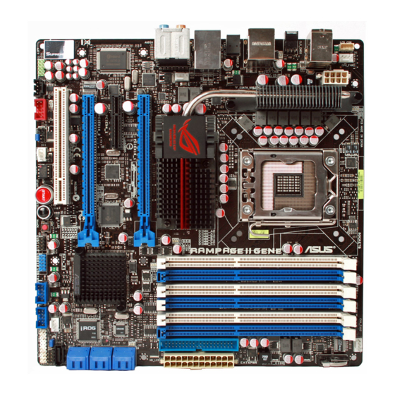
Page 30: Motherboard Overview
Motherboard overview 2.2.1 Motherboard layout Chapter 2: Hardware information... -
Page 31: Layout Contents
2.2.2 Layout contents Connectors/Jumpers/Switches/Slots Page CPU, chassis, and optional fan connectors (4-pin CPU_FAN; 2-35 3-pin CHA_FAN1–2; 3-pin OPT_FAN1–2) ATX power connectors (24-pin EATXPWR, 8-pin EATX12V) 2-37 LGA1366 CPU Socket 2-10 DDR3 DIMM slots 2-15 IDE connector (40-1 pin PRI_EIDE) 2-30 ICH10R Serial ATA connectors (7-pin SATA1–6 [blue]) 2-31 JMicron JMB363... -
Page 32: Placement Direction
2.2.3 Placement direction When installing the motherboard, ensure that you place it into the chassis in the correct orientation. The edge with external ports goes to the rear part of the chassis as indicated in the image below. 2.2.4 Screw holes Place eight (8) screws into the holes indicated by circles to secure the motherboard to the chassis. -
Page 33: Central Processing Unit (Cpu)
ASUS will shoulder the cost of repair only if the damage is shipment/transit-related. • Keep the cap after installing the motherboard. ASUS will process Return Merchandise Authorization (RMA) requests only if the motherboard comes with the cap on the LGA1366 socket. -
Page 34: Installing The Cpu
2.3.1 Installing the CPU To install a CPU: Locate the CPU socket on the motherboard. Before installing the CPU, ensure that the cam box is facing towards you and the load lever is on your left. Press the load lever with your Retention tab thumb (A), then move it to the left (B) until it is released from the... - Page 35 Lift the load lever in the direction of the arrow to a 135º angle. Load plate Lift the load plate with your thumb and forefinger to a 100º angle. Remove the PnP cap from the CPU socket. PnP cap Position the CPU over the socket, ensuring that the gold triangle is on the bottom-left corner of the socket, and then fit the socket alignment key...
- Page 36 Apply several drops of thermal paste to the exposed area of the CPU that the heatsink will be in contact with, ensuring that it is spread in an even thin layer. Some heatsinks come with pre- applied thermal paste. If so, skip this step.
-
Page 37: Installing The Cpu Heatsink And Fan
2.3.2 Installing the CPU heatsink and fan The Intel LGA1366 processor requires a specially designed heatsink and fan ® assembly to ensure optimum thermal condition and performance. • When you buy a boxed Intel processor, the package includes the CPU fan ®... -
Page 38: Uninstalling The Cpu Heatsink And Fan
Connect the CPU fan cable to the connector on the motherboard labeled CPU_FAN. DO NOT forget to connect the CPU fan connector! Hardware monitoring errors can occur if you fail to plug this connector. 2.3.3 Uninstalling the CPU heatsink and fan To uninstall the CPU heatsink and fan: Disconnect the CPU fan cable from the connector on the motherboard. -
Page 39: System Memory
System memory 2.4.1 Overview The motherboard comes with six Double Data Rate 3 (DDR3) Dual Inline Memory Modules (DIMM) sockets. A DDR3 module has the same physical dimensions as a DDR2 DIMM but is notched differently to prevent installation on a DDR2 DIMM socket. DDR3 modules are developed for better performance with less power consumption. -
Page 40: Memory Configurations
2.4.2 Memory configurations You may install 1GB, 2GB and 4GB unbuffered non-ECC DDR3 DIMMs into the DIMM sockets. • You may install varying memory sizes in Channel A, Channel B and Channel C. The system maps the total size of the lower-sized channel for the dual-channel or triple-channel configuration. - Page 41 C1) as one set of Triple-channel memory configuration. • ASUS exclusively provides hyper DIMM support function. • Hyper DIMM support is subject to the physical characteristics of individual CPUs. • Visit the ASUS website for the latest QVL. ROG Rampage II GENE 2-17...
- Page 42 Rampage II GENE Motherboard Qualified Vendors Lists (QVL) DDR3-1600MHz capability DIMM socket support (Optional) Timing Vendor Part No. Size Chip Chip NO. Voltage Dimm(Bios) Heat-Sink 8-8-8-24 1.65- A-DATA AD31600E001GMU(XMP) • • • • (Kit of 3) Package (1333-9-9-9-24) 1.85 Heat-Sink 7-7-7-20 1.75- A-DATA...
- Page 43 Rampage II GENE Motherboard Qualified Vendors Lists (QVL) DDR3-1600MHz capability (continued) DIMM socket support (Optional) Timing Vendor Part No. Size Chip Chip NO. Voltage Dimm(Bios) Heat-Sink 7-7-7-14 Cell Shock CS322271 1.7-1.9 • • • (Kit of 2) Package (1066-7-7-7-20) N2CB1G80AN- Elixier M2F2G64CB8HA4N-DG Elixir...
- Page 44 Asint SLY3128M8-EDJ Asint DDRIII1208-DJ (9-9-9-24) • • • • Asint SLZ3128M8-EDJ Asint DDRIII1208-DJ (9-9-9-24) • • • • ASUS Heat-Sink Package (1333-9-9-9-24) • • • Elixir M2F2G64CB8HA4N-CG Elixir N2CB1G80AN-CG (1333-9-9-9-24) • • • Patriot PDC32G1333LLK PATRIOT Heat-Sink Package 7 (1337-7-7-7-20) •...
- Page 45 Triple-channel memory configuration. • According to Intel spec definition, DDR3-1600 is supported for one DIMM per channel only. ASUS exclusively provides two DDR3-1600 DIMM support for each memory channel. • Visit the ASUS website for the latest QVL.
-
Page 46: Installing A Dimm
2.4.3 Installing a DIMM Ensure to unplug the power supply before adding or removing DIMMs or other system components. Failure to do so may cause severe damage to both the motherboard and the components. Unlock a DIMM socket by DIMM notch pressing the retaining clip outward. -
Page 47: Expansion Slots
Expansion slots In the future, you may need to install expansion cards. The following sub-sections describe the slots and the expansion cards that they support. Ensure to unplug the power cord before adding or removing expansion cards. Failure to do so may cause you physical injury and damage motherboard components. -
Page 48: Interrupt Assignments
2.5.3 Interrupt assignments Standard interrupt assignments Priority Standard function System Timer Keyboard Controller – Redirect to IRQ#9 Communications Port (COM1)* IRQ Holder for PCI Steering* Reserved Reserved System CMOS/Real Time Clock IRQ Holder for PCI Steering* IRQ Holder for PCI Steering* IRQ Holder for PCI Steering* Reserved Numeric Data Processor... -
Page 49: Pci Slot
2.5.4 PCI slot The PCI slot supports cards such as a LAN card, SCSI card, USB card, and other cards that comply with PCI specifications. Refer to the figure below for the location of the slot. 2.5.5 PCI Express x4 slot This motherboard supports PCI Express x4 network cards, SCSI cards and other cards that comply with the PCI Express specifications. - Page 50 • In single VGA card mode, use first the PCIe 2.0 x16_1 slot for a PCI Express x16 graphics card to get better performance. • In CrossFireX™ or SLI™ mode, use the PCIe 2.0 x16_1 and PCIe 2.0 x16_2 (blue) slots for PCI Express x16 graphics cards to get better performance.
-
Page 51: Jumper
Jumper Clear RTC RAM (3-pin CLRTC_SW) This jumper allows you to enable the clr CMOS switch on the back I/O. You can clear the CMOS memory and system setup parameters by erasing the CMOS RTC RAM data. The clr CMOS switch on the back I/O helps you easily clear the system setup information such as system passwords. -
Page 52: Connectors
Connectors 2.7.1 Rear panel connectors PS/2 keyboard port (purple). This port is for a PS/2 keyboard. USB 2.0 ports 3 and 4. These 4-pin Universal Serial Bus (USB) ports are available for connecting USB 2.0 devices. LAN (RJ-45) port. This port allows Gigabit connection to a Local Area Network (LAN) through a network hub. - Page 53 IEEE 1394a port. This 6-pin IEEE 1394a port provides high-speed connectivity for audio/video devices, storage peripherals, PCs, or portable devices. External SATA port. This port connects to an external Serial ATA hard disk drive. • DO NOT insert a SATA connector into this external SATA port. To enable hot-plugging, set the Controller Mode item in the BIOS setting •...
-
Page 54: Internal Connectors
2.7.2 Internal connectors IDE connector (40-1 pin PRI_EIDE) The onboard IDE connector is for the Ultra DMA 133/100/66 signal cable. There are three connectors on each Ultra DMA 133/100/66 signal cable: blue, black, and gray. Connect the blue connector to the motherboard’s IDE connector, then select one of the following modes to configure your device. - Page 55 ICH10R Serial ATA connectors (7-pin SATA 1-6 [blue]) These connectors are for the Serial ATA signal cables for Serial ATA hard disk drives and optical disc drives. If you installed Serial ATA hard disk drives, you can create a RAID 0, 1, 5, and 10 configuration with the Intel Matrix Storage Technology through the ®...
- Page 56 480 Mbps connection speed. Never connect a 1394 cable to the USB connectors. Doing so will damage the motherboard! You can connect the USB cable to ASUS Q-Connector (USB, blue) first, and then install the Q-Connector (USB) to the USB connector onboard. 2-32...
- Page 57 IEEE 1394a port connector (10-1 pin IE1394_2) This connector is for an IEEE 1394a port. Connect the IEEE 1394a module cable to this connector, then install the module to a slot opening at the back of the system chassis. Never connect a USB cable to the IEEE 1394a connector. Doing so will damage the motherboard! Digital audio connector (4-1 pin SPDIF_OUT) This connector is for an additional Sony/Philips Digital Interface (S/PDIF)
- Page 58 Optical drive audio connector (4-pin CD) These connectors allow you to receive stereo audio input from sound sources such as a CD-ROM, TV tuner, or MPEG card. Front panel audio connector (10-1 pin AAFP) This connector is for a chassis-mounted front panel audio I/O module that supports either HD Audio or legacy AC`97 audio standard.
- Page 59 CPU, chassis, and optional fan connectors (4-pin CPU_FAN, 3-pin CHA_FAN1–2, 3-pin OPT_FAN1–2) The fan connectors support cooling fans of 350 mA–2000 mA (24 W max.) or a total of 1 A–7 A (84 W max.) at +12V. Connect the fan cables to the fan connectors on the motherboard, ensuring that the black wire of each cable matches the ground pin of the connector.
- Page 60 10. Thermal sensor cable connectors (2-pin OPT_TEMP1/2) These connectors are for temperature monitoring. Connect the thermal sensor cables to these connectors and place the other ends to the devices which you want to monitor temperature. The optional fan1/2 can work with the temperature sensors for a better cooling effect.
- Page 61 • If you are uncertain about the minimum power supply requirement for your system, refer to the Recommended Power Supply Wattage Calculator at http://support.asus.com/PowerSupplyCalculator/PSCalculator. aspx?SLanguage=en-us for details. • If you want to use two high-end PCI Express x16 cards, use a PSU with 1000W power or above to ensure the system stability.
-
Page 62: System Panel Connector
13. System panel connector (20-8 pin PANEL) This connector supports several chassis-mounted functions. • System power LED (2-pin PLED) This 2-pin connector is for the system power LED. Connect the chassis power LED cable to this connector. The system power LED lights up when you turn on the system power, and blinks when the system is in sleep mode. - Page 63 ASUS Q-Connector (system panel) You can use the ASUS Q-Connector to connect/disconnect chassis front panel cables in a few steps. Refer to the instructions below to install the ASUS Q-Connector. Connect the front panel cables to the ASUS Q-Connector. Refer to the labels on the Q-Connector...
-
Page 64: Onboard Switches
2.7.3 Onboard switches Onboard switches allow you to fine-tune performance when working on a bare or open-case system. This is ideal for overclockers and gamers who continually change settings to enhance system performance. Power-on switch Press the power-on switch to wake/power up the system. Reset switch Press the reset switch to reboot the system. - Page 65 MemOK! switch Press the MemOK! switch to load failsafe settings for memory compatibility and improving system boot success. ROG Rampage II GENE 2-41...
-
Page 66: Installing I/O Shield And Lcd Poster
2.7.4 Installing I/O shield and LCD Poster Install the I/O shield to the Orient the motherboard and install chassis by snaping it in place it to the chassis. Ensure that the from inside. motherboard external ports fit the shield openings. Thread the LCD Poster cable Locate and connect the LCD Poster cable to the LCD_CON... -
Page 67: Starting Up For The First Time
Starting up for the first time After making all the connections, replace the system case cover. Be sure that all switches are off. Connect the power cord to the power connector at the back of the system chassis. Connect the power cord to a power outlet that is equipped with a surge protector. -
Page 68: Turning Off The Computer
Turning off the computer 2.9.1 Using the OS shut down function If you are using Windows Vista™: ® Click the Start button then select Shut Down. The power supply should turn off after Windows shuts down. ® If you are using Windows ®... -
Page 69: Chapter 3: Bios Setup
This chapter tells how to change the system settings through the BIOS Setup menus. Detailed descriptions of the BIOS parameters are also provided. BIOS setup... - Page 70 Chapter summary Managing and updating your BIOS ..........3-1 BIOS setup program ..............3-6 Extreme Tweaker menu ............... 3-9 Main menu .................. 3-18 Advanced menu ................. 3-22 Power menu ................3-30 Boot menu .................. 3-35 Tools menu ................. 3-39 Exit menu ..................3-43 ROG Rampage II GENE...
-
Page 71: Managing And Updating Your Bios
® ASUS EZ Flash 2 (Updates the BIOS using a floppy disk or USB flash disk.) ASUS CrashFree BIOS 3 utility: Restores the BIOS using the motherboard support DVD or a USB flash drive when the BIOS file fails or gets corrupted. - Page 72 To update the BIOS through the Internet: desktop by clicking Start Launch the ASUS Update utility from the Windows ® > Programs > ASUS > ASUSUpdate > ASUSUpdate. The ASUS Update main window appears. Select Update BIOS from the Select the ASUS FTP site nearest...
- Page 73 To update the BIOS through a BIOS file: desktop by clicking Start Launch the ASUS Update utility from the Windows ® > Programs > ASUS > ASUSUpdate > ASUSUpdate. The ASUS Update main window appears. Select Update BIOS from a file option from the drop-down menu, then click Next.
-
Page 74: Asus Ez Flash 2 Utility
3.1.2 ASUS EZ Flash 2 utility The ASUS EZ Flash 2 feature allows you to update the BIOS without having to use a DOS-based utility. The EZ Flash 2 utility is built in the BIOS chip so it is accessible by pressing <Alt> + <F2> during the Power-On Self Tests (POST). -
Page 75: Asus Crashfree Bios 3 Utility
3.1.3 ASUS CrashFree BIOS 3 utility The ASUS CrashFree BIOS 3 utility is an auto recovery tool that allows you to restore the BIOS file when it fails or gets corrupted during the updating process. You can restore a corrupted BIOS file using the motherboard support DVD or a USB flash drive that contains the BIOS file. -
Page 76: Bios Setup Program
The BIOS setup screens shown in this section are for reference purposes only, and may not exactly match what you see on your screen. • Visit the ASUS website (www.asus.com) to download the latest BIOS file for this motherboard. Chapter 3: BIOS setup... -
Page 77: Bios Menu Screen
3.2.1 BIOS menu screen Menu items Menu bar Configuration fields General help BIOS SETUP UTILITY Extreme Tweaker Main Advanced Power Boot Tools Exit Use [ENTER], [TAB] System Time [13:51:25] or [SHIFT-TAB] to System Date [Wed 02/04/2009] select a field. Language [English] Use [+] or [-] to SATA1... -
Page 78: Menu Items
3.2.4 Menu items The highlighted item on the menu bar displays the specific items for that menu. For example, selecting Main shows the Main menu items. The other items (Advanced, Power, Boot, and Exit) on the menu bar have their respective menu items. -
Page 79: Extreme Tweaker Menu
Extreme Tweaker menu The Extreme Tweaker menu items allow you to configure overclocking-related items. Take caution when changing the settings of the Extreme Tweaker menu items. Incorrect field values can cause the system to malfunction. The default values of the following items vary depending on the CPU and memory modules you install on the motherboard. -
Page 80: Tuning Mode
Configure System Performance Settings The configuration options may vary depending on your CPU/memory model. 3.3.1 Tuning Mode [Extreme OC] The Tuning Mode item is the Extreme Tweaker menu item switch for different purpose. The Extreme OC mode offers the maximum tuning degree of freedom to the extreme. -
Page 81: Cpu Configuration
OC From CPU Level Up [Auto] After you select a CPU level and set Ai Overclock Tuner to [Manual], the related parameters will be adjusted accordingly. Configuration options: [Auto] [i7-940-2.93G] [i7-965-3.20G] [i7-crazy-3.60G] [i7-crazy-4.00G] OC From Memory Level Up [Auto] After you select a memory level and set Ai Overclock Tuner to [Manual], the related parameters will be adjusted accordingly. -
Page 82: Dram Timing Control
PCIE Frequency [XXX] Allows you to set the PCI Express frequency. Use the <+> and <-> keys to adjust the PCIE frequency. You can also type the desired value using the numeric keypad. The values range from 100 to 200. 3.3.7 DRAM Frequency [Auto] Allows you to set the DDR3 operating frequency. -
Page 83: Epu Ii Phase Control
DRAM FOUR ACT WIN Time [Auto] Configuration options: [Auto] [1 DRAM Clock] – [63 DRAM Clock] DRAM Back-To-Back CAS# Delay [Auto] Configuration options: [Auto] [4 DRAM Clock] – [32 DRAM Clock] 2nd Information: 1N-66-0-0 (These values are auto-detected) (These values are auto-detected) DRAM Timing Mode [Auto] Configuration options: [Auto] [1N] [2N] [3N] DRAM Round Trip Latency on CHA/B/C [Auto]... -
Page 84: Cpu Load-Line Calibration
3.3.10 CPU Load-Line Calibration [Auto] Allows you to select the CPU Load-Line mode. Set to [Disabled] to follow Intel specifications, or to [Enabled] to improve CPU VDroop directly. Configuration options: [Auto] [Disabled] [Enabled] 3.3.11 QPI Load-Line Calibration [Disabled] Allows you to select the QPI Load-Line mode. Set to [Disabled] to follow Intel specifications, or to [Enabled] to improve QPI VDroop directly. -
Page 85: Cpu Pll Voltage
Refer to the CPU documentation before setting the CPU VCore voltage. Setting a high voltage may damage the CPU permanently, and setting a low voltage may make the system unstable. 3.3.17 CPU PLL Voltage [Auto] Allows you to select the CPU PLL voltage. The text color in the configuration field corresponds to the onboard CPU LED color, both of which indicate voltage condition. -
Page 86: Dram Ref Voltages
The values of the CPU Voltage, CPU PLL Voltage, QPI/DRAM Core • Voltage, IOH Voltage, IOH PCIE Voltage, ICH Voltage, ICH PCIE Voltage, and DRAM Bus Voltage items are labeled in different color, indicating the risk levels of high voltage settings. Refer to below table for details. •... -
Page 87: Cpu Clock Skew
3.3.29 CPU Clock Skew [Auto] Adjusting this item may help enhancing BCLK overclocking ability. You may need to adjust the IOH Clock Skew item at the same time. Configuration options: [Auto] [Normal] [Delay 100ps]–[Delay 1500ps] 3.3.30 IOH Clock Skew [Auto] Adjusting this item may help enhancing BCLK overclocking ability. -
Page 88: System Time
Main menu When you enter the BIOS Setup program, the Main menu screen appears, giving you an overview of the basic system information. Refer to section 3.2.1 BIOS menu screen for information on the menu screen items and how to navigate through them. BIOS SETUP UTILITY Extreme Tweaker Main... -
Page 89: Sata 1–6
3.4.4 SATA 1–6 While entering Setup, the BIOS automatically detects the presence of Serial ATA devices. There is a separate sub-menu for each SATA device. Select a device item then press <Enter> to display the SATA device information. BIOS SETUP UTILITY Main SATA 1 Select the type... -
Page 90: Storage Configuration
DMA Mode [Auto] Selects the DMA mode. Configuration options: [Auto] SMART Monitoring [Auto] Sets the Smart Monitoring, Analysis, and Reporting Technology. Configuration options: [Auto] [Disabled] [Enabled] 32Bit Data Transfer [Enabled] Enables or disables 32-bit data transfer. Configuration options: [Disabled] [Enabled] 3.4.5 Storage Configuration The items in this menu allow you to set or change the configurations for the SATA... -
Page 91: System Information
Hard Disk Write Protect [Disabled] Disables or enables device write protection. This will be effective only if device is accessed through BIOS. Confiuration option: [Disabled] [Enabled] SATA Detect Time Out (Sec) [35] Selects the time out value for detecting ATA/ATAPI devices. Configuration options: [0] [5] [10] [15] [20] [25] [30] [35] 3.4.6 System Information... -
Page 92: Cpu Ratio Setting
Advanced menu The Advanced menu items allow you to change the settings for the CPU and other system devices. BIOS SETUP UTILITY Extreme Tweaker Main Advanced Power Boot Tools Exit Configure CPU. CPU Configuration Chipset Onboard Devices Configuration USB Configuration PCIPnP LCD Poster and LED Control iROG Configuration... - Page 93 CPU Ratio Setting [Auto] Allows you to adjust the ratio between CPU Core Clock and BCLK Frequency. Use the <+> and <-> keys to adjust the value. The valid value ranges differently according to your CPU model. C1E Support [Enabled] Allows you to enable or disable Enhanced Halt State support.
-
Page 94: Chipset
*Intel(R) SpeedStep(TM) Tech [Enabled] When set to [Disabled], the CPU runs at its default speed. When set to [Enabled], the CPU speed is controlled by the operating system. Configuration options: [Disabled] [Enabled] *Intel(R) TurboMode tech [Enabled] Turbo mode allows processor cores to run faster than marked frequency in specific condition. -
Page 95: Onboard Device Configuration
3.5.3 Onboard Device Configuration BIOS SETUP UTILITY Advanced Onboard Device Configuration Get your best overclocking record! Onboard Device [Standard] “Onboard Device” is to disable all the High Definition Audio [Enabled] unnecessary devices Front Panel Type [HD Audio] when you want to J-Micron eSATA/PATA Controller [Enabled] reach you best Controller Mode... -
Page 96: Usb Configuration
Onboard 1394 Controller [Enabled] Allows you to enabled or disable the onboard IEEE 1394a controller. Configuration options: [Enabled] [Disabled] 3.5.4 USB Configuration The items in this menu allows you to change the USB-related features. Select an item then press <Enter> to display the configuration options. BIOS SETUP UTILITY Advanced USB Configuration... -
Page 97: Pci Pnp
Legacy USB Support [Auto] Allows you to enable or disable the support for legacy USB devices. Setting to [Auto] allows the system to detect the presence of USB devices at startup. If detected, the USB controller legacy mode is enabled. If no USB device is detected, the legacy USB support is disabled. -
Page 98: Lcd Poster And Led Control
3.5.6 LCD Poster and LED Control BIOS SETUP UTILITY Advanced LCD Poster and LED Control Turn On/Turn Off LCD Poster when system LCD Poster Backlight [Turn Off] is working LCD Poster Backlight(S5) [Turn Off] LCD Poster Mode [Current Time] All LED Control [Enabled] Voltiminder LED [Enabled]... -
Page 99: Irog Configuration
CPU LED Selection [CPU] Allows you to switch the onboard CPU LED display between CPU voltage [CPU], CPU PLL voltage [CPU PLL] and QPI/DRAM Core voltage [QPI/DRAM Core]. Configuration options: [CPU] [CPU PLL] [QPI/DRAM Core] NB LED Selection [IOH] Allows you to switch the onboard northbridge LED display between I/O Hub voltage [IOH] and IOH PCIE voltage [IOH PCIE]. -
Page 100: Power Menu
Power menu The Power menu items allow you to change the settings for the Advanced Power Management (APM). Select an item then press <Enter> to display the configuration options. BIOS SETUP UTILITY Extreme Tweaker Main Main Advanced Advanced Power Boot Tools Exit Select the ACPI state... -
Page 101: Apm Configuration
3.6.5 APM Configuration BIOS SETUP UTILITY Power APM Configuration Options Power Off Restore on AC Power Loss [Power Off] Power On Last State Power On By RTC Alarm [Disabled] Power On By PCI Devices [Disabled] Power On By PCIE Devices [Disabled] Power On By PS/2 Keyboard [Disabled]... -
Page 102: Hardware Monitor
3.6.6 Hardware Monitor BIOS SETUP UTILITY Power Hardware Monitor Voltage Monitor Voltage Monitor Temperature Monitor Fan Speed Monitor Fan Speed Control Voltage Monitor CPU Voltage; CPU PLL Voltage; QPI/DRAM Core Voltage; IOH Voltage; IOH PCIE Voltage; ICH Voltage; ICH PCIE Voltage; DRAM Bus Voltage; 3.3V Voltage;... -
Page 103: Fan Speed Control
The following item appears when you enable CPU Q-Fan Control. CPU Fan Profile [Standard] Allows you to set the appropriate performance level of the ASUS Q-Fan. When set to [Standard], the CPU fan automatically adjusts depending on the CPU temperature. Set this item to [Silent] to minimize fan speed for quiet CPU fan operation, or [Turbo] to achieve maximum CPU fan speed. - Page 104 OPTFan1/2 Duty [50%] Allows you to set the fan duty cycle. This item appears when the OPTFan1/2 Control item is set to [Duty Mode]. Configuration options: [40%] [50%] [60%] [70%] [80%] [90%] OPTFan1/2 Low Speed Temp [25˚C] Allows you to set the temperature at which the power fan rotates at low speed. This item appears when the OPTFan1/2 Control item is set to [User Mode].
-
Page 105: Boot Menu
Boot menu The Boot menu items allow you to change the system boot options. Select an item then press <Enter> to display the sub-menu. BIOS SETUP UTILITY Extreme Tweaker Main Main Advanced Advanced Power Power Boot Tools Exit Specifies the Boot Boot Settings Device Priority sequence. -
Page 106: Boot Settings Configuration
BIOS performs all the POST items. Configuration options: [Disabled] [Enabled] Full Screen Logo [Enabled] This allows you to enable or disable the full screen logo display feature. Configuration options: [Disabled] [Enabled] Set this item to [Enabled] to use the ASUS MyLogo3 feature. ™ AddOn ROM Display Mode [Force BIOS] Sets the display mode for option ROM. -
Page 107: Security
3.7.3 Security The Security menu items allow you to change the system security settings. Select an item then press <Enter> to display the configuration options. BIOS SETUP UTILITY Boot Security Settings <Enter> to change password. Supervisor Password :Not Installed <Enter> again to User Password :Not Installed disabled password. -
Page 108: Change User Password
After you have set a supervisor password, the other items appear to allow you to change other security settings. BIOS SETUP UTILITY Boot Security Settings <Enter> to change password. Supervisor Password :Installed <Enter> again to User Password :Installed disabled password. Change Supervisor Password User Access Level [Full Access]... -
Page 109: Tools Menu
(C)Copyright 1985-2009, American Megatrends, Inc. 3.8.1 ASUS EZ Flash 2 Allows you to run ASUS EZ Flash 2. When you press <Enter>, a confirmation message appears. Use the left/right arrow key to select between [Yes] or [No], then press <Enter> to confirm your choice. -
Page 110: Asus O.c. Profile
3.8.2 ASUS O.C. Profile This item allows you to store or load multiple BIOS settings. BIOS SETUP UTILITY Tools O.C. PROFILE Configuration Typing your profile name, [0-9][a-z][A-Z] O.C. Profile 1 Status : Not Installed are acceptable. O.C. Profile 2 Status : Not Installed O.C. -
Page 111: Tweakit Batch File
• This function supports devices such as a USB flash disk (FAT 32/16 format) or a floppy disk with single partition only. • DO NOT shut down or reset the system while updating the BIOS to prevent the system boot failure! •... - Page 112 3.8.4 AI NET 2 BIOS SETUP UTILITY Tools Ai Net 2 Check Realtek LAN Pair Status Length cable during POST. It will take 3 to 10 seconds to diagnose Check Realtek LAN cable [Disabled] LAN cable. Check Realtek LAN cable [Disabled] Enables or disables checking of the LAN cable during the Power-On Self-Test (POST).
-
Page 113: Exit Menu
Exit menu The Exit menu items allow you to load the optimal or failsafe default values for the BIOS items, and save or discard your changes to the BIOS items. BIOS SETUP UTILITY Main Extreme Tweaker Advanced Power Boot Tools Exit Exit system setup after Exit Options... - Page 114 3-44 Chapter 3: BIOS setup...
-
Page 115: Software Support
This chapter describes the contents of the support DVD that comes with the motherboard package and the software. Software support... - Page 116 Chapter summary Installing an operating system ........... 4-1 Support DVD information ............4-1 Software information ..............4-9 RAID configurations ..............4-33 Creating a RAID driver disk ............4-40 ROG Rampage II GENE...
-
Page 117: Installing An Operating System
The contents of the support DVD are subject to change at any time without notice. Visit the ASUS website (www.asus.com) for updates. 4.2.1 Running the support DVD Place the support DVD to the optical drive. -
Page 118: Drivers Menu
The drivers menu shows the available device drivers if the system detects installed devices. Install the necessary drivers to activate the devices. ASUS InstAll - Drivers Installation Wizard Launches the ASUS InstAll driver installation wizard. Intel Chipset Inf Update Program Installs the Intel chipset inf update program. -
Page 119: Utilities Menu
ASUS InstAll - Installation Wizard for Utilities Installs all of the utilities through the Installation Wizard. ASUS Update The ASUS Update utility allows you to update the motherboard BIOS in Windows ® environment. This utility requires an Internet connection either through a network or an Internet Service Provider (ISP). - Page 120 Installs the ASUS AI Suite. ASUS AI Direct Link The ASUS AI Direct Link provides up to 70% transferring speed improvement when compared to traditional USB 2.0 and is the easiest and fastest way for users to enjoy large-sized data exchange of files such as movies, music, etc.
-
Page 121: Make Disk Menu
4.2.4 Make disk menu The Make disk menu contains items to create the Intel ICH10R driver disk. Intel ICH10R 32/64 bit AHCI/RAID Driver Allows you to create an ICH10R 32/64bit AHCI/RAID driver disk. JMicron JMB36X 32/64 bit RAID/AHCI Driver Allows you to create a JMicron JMB36X RAID/AHCI driver disk for 32/64bit ®... -
Page 122: Video Menu
ROG users’ outstanding performances with ROG motherboards. 4.2.7 ASUS Contact information Click the Contact tab to display the ASUS contact information. You can also find this information on the inside front cover of this user guide. Chapter 4: Software support... -
Page 123: Other Information
4.2.8 Other information The icons on the top right corner of the screen give additional information on the motherboard and the contents of the support DVD. Click an icon to display the specified information. Motherboard Info Displays the general specifications of the motherboard. Browse this DVD Displays the support DVD contents in graphical format. -
Page 124: Technical Support Form
Technical support form Displays the ASUS Technical Support Request Form that you have to fill out when requesting technical support. Filelist Displays the contents of the support DVD and a brief description of each in text format. Chapter 4: Software support... -
Page 125: Software Information
4.3.1 ASUS MyLogo3™ The ASUS MyLogo3™ utility lets you customize the boot logo. The boot logo is the image that appears on screen during the Power-On Self-Tests (POST). The ASUS MyLogo3™ is automatically installed when you install the ASUS Update utility from the support DVD. - Page 126 Ratio box. When the screen returns to the ASUS Update utility, flash the original BIOS to load the new boot logo. 10. After flashing the BIOS, restart the computer to display the new boot logo during POST.
-
Page 127: Sound Blaster X-Fi Audio Utility
4.3.2 Sound Blaster X-Fi audio utility With the SupremeFX X-Fi technology supported, you will be able to enjoy excellent audio quality and experience realistic sound effects through the ADI AD2000B audio codec and Sound Blaster X-Fi interface. Activating X-Fi’s CMSS3D, Crystalizer, and EAX will deliver accurate virtual surround sound and enhanced audio dynamics, which amount to ultimate gaming experience. -
Page 128: Speakers And Headphone Panel
Main Panel The Main Panel displays all the features and functions the SupremeFX X-Fi supports. Click each icon to configure the following settings (from left to right): Speakers and Headphone, EAX Effects, X-Fi CMSS-3D, X-Fi Crystalizer, Smart Volume Management, Graphic Equalizer, and Mixer. Minimize Exit Help... - Page 129 EAX Effects Panel This panel contains environment effects that you can select to obtain a sense of realism during interactive 3D games. Click to enable EAX Effects Drag to adjust effects amount Click to select an environment X-Fi CMSS-3D Panel This panel allows you to configure 3D virtual surround effects.
- Page 130 Smart Volume Management Panel Enable Smart Volume Management (SVM) to avoid large volume fluctuations. Click to switch on/off SVM Graphic Equalizer Panel This panel allows you to customize equalizer settings or select an EQ presets. Click to select Click to an EQ preset enable EQ Click to save...
-
Page 131: Asus Pc Probe Ii
To launch the PC Probe II from the Windows ® > ASUS > PC Probe II > PC Probe II v1.xx.xx. The PC Probe II main window appears. After launching the application, the PC Probe II icon appears in the Windows ®... - Page 132 Button Function Opens the Configuration window Opens the Report window Opens the Desktop Management Interface window Opens the Peripheral Component Interconnect window Opens the Windows Management Instrumentation window Opens the hard disk drive, memory, CPU usage window Shows/Hides the Preference section Minimizes the application Closes the application Sensor alert...
- Page 133 Hardware monitor panels The hardware monitor panels display the current value of a system sensor such as fan rotation, CPU temperature, and voltages. The hardware monitor panels come in two display modes: hexagonal (large) and rectangular (small). When you check the Enable Monitoring Panel option from the Preference section, the monitor panels appear on your computer’s desktop.
- Page 134 Monitoring sensor alert The monitor panel turns red when a component value exceeds or is lower than the threshold value. Refer to the illustrations below. Small display Large display WMI browser Click to display the WMI (Windows Management Instrumentation) browser. This browser displays various Windows®...
- Page 135 PCI browser Click to display the PCI (Peripheral Component Interconnect) browser. This browser provides information on the PCI devices installed on your system. Click the plus sign (+) before the PCI Information item to display available information. Usage The Usage browser displays real-time information on the CPU, hard disk drive space, and memory usage.
- Page 136 Memory usage The Memory tab shows both used and available physical memory. The pie chart at the bottom of the window represents the used (blue) and the available physical memory. Configuring PC Probe II Click to view and adjust the sensor threshold values. The Config window has two tabs: Sensor/Threshold and Preference.
-
Page 137: Asus Ai Suite
4.3.4 ASUS AI Suite ASUS AI Suite allows you to launch EPU-6 Engine, TurboV, Fan Xpert, CPU Level Fan Xpert, CPU Level Up, and AI Nap utilities easily. AI Nap utilities easily. Installing AI Suite To install AI Suite on your computer: Place the support DVD to the optical drive. - Page 138 Other feature buttons Click on right corner of the main window to open the monitor window. Displays the CPU/ system temperature, CPU/memory/PCIE voltage, and CPU/ chassis fan speed Displays the FSB/CPU frequency Click on right corner of the expanded window to switch the temperature from degrees Centigrade to degrees Fahrenheit.
-
Page 139: Asus Ai Nap
4.3.5 ASUS AI Nap This feature allows you to minimize the power consumption of your computer whenever you are away. Enable this feature for minimum power consumption and a more quiet system operation. After installing AI Suite from the bundled support DVD, you can launch the utility by double-clicking the AI Suite icon on the Windows OS taskbar and click the AI Nap button on the AI Suite main window. -
Page 140: Asus Fan Xpert
4.3.6 ASUS Fan Xpert Asus Fan Xpert intelligently allows you to adjust both the CPU and chassis fan speeds according to different ambient temperatures caused by different climate conditions in different geographic regions and your PC’s system loading. The built-in variety of useful profiles offer flexible controls of fan speed to achieve a quiet and cool environment. -
Page 141: Fan Profile Modes
Fan profile modes Disable: Select this mode to disable the Fan Xpert function. • Standard: This mode makes the fan adjust speed in moderate pattern. • Silent: This mode minimizes fan speed for quiet fan operation. • Turbo: This mode boosts the fan to achieve maximal fan speed for the best •... -
Page 142: Cpu Level Up
4.3.7 CPU Level Up The CPU Level Up allows you to overclock immediately with OC profile presets in WIndows environment without the hassle of entering BIOS. ® After installing AI Suite from the bundled Support DVD, launch the utility by double- clicking the AI Suite icon on the Windows OS taskbar and click the CPU Level Up ®... - Page 143 4.3.8 ASUS EPU-6 Engine ASUS EPU-6 Engine is an energy-efficient tool that satisfies different computing needs. This utility provides four modes that you can select to enhance system performance or save power. Selecting Auto mode will have the system shift modes automatically according to current system status.
-
Page 144: Engine Main Menu
6 Engine main menu Displays CPU Power and Total CPU Energy Saving Lights up when power saving engine is activated Displays the following message if no VGA power saving engine is detected. *Shifts between Displays the the display of Total amount of CO2 and Current CO2 reduced... -
Page 145: Advanced Settings Menu
Advanced settings menu Click Setting ( ) from the 6 Engine main menu to display configuration options in each mode. Some options in certain modes are dimmed, meaning that they are not available. Click to select a mode Move the slider to adjust Click the arrow to see more... - Page 146 • Fan Control: Adjusts fan speeds to reduce noise and save system power. • Quiet: Lowers CPU fan speed and shuts off two chassis fans. • Slow: Lowers CPU fan and two chassis fan speeds. • AI Nap Idle Time: Enters AI Nap mode after a certain time during system idle process.
-
Page 147: Asus Turbov
• For system stability, all changes made in ASUS TurboV will not be saved to BIOS settings and will not be kept on the next system boot. Use the Save Profile function to save your customized overclocking settings and manually load the profile after Windows starts. - Page 148 Advanced settings menu Click More Setting from the TurboV main screen to display detailed configuration options for CPU/chip voltage, DRAM Reference voltage, and CPU ratio. Advance Mode Advanced CPU and DRAM voltage settings CPU Ratio Mode Adjusts CPU core ratio Displays CPU frequency •...
-
Page 149: Raid Configurations
RAID configurations The motherboard comes with the Intel ICH10R Southbridge controller that ® supports RAID 0, RAID 1, RAID 10, and RAID 5 for six independent Serial ATA channels. 4.4.1 RAID definitions RAID 0 (Data striping) optimizes two identical hard disk drives to read and write data in parallel, interleaved stacks. -
Page 150: Installing Serial Ata Hard Disks
4.4.2 Installing Serial ATA hard disks The motherboard supports Serial ATA hard disk drives. For optimal performance, install identical drives of the same model and capacity when creating a disk array. To install the SATA hard disks for a RAID configuration: Install the SATA hard disks into the drive bays. - Page 151 4.4.4 Intel Matrix Storage Manager option ROM utility ® The Intel Matrix Storage Manager Option ROM utility allows you to create RAID 0, ® RAID 1, RAID 10 (RAID 0+1), and RAID 5 set(s) from Serial ATA hard disk drives that are connected to the Serial ATA connectors supported by the Southbridge.
-
Page 152: Creating A Raid Set
Creating a RAID set To create a RAID set From the utility main menu, select 1. Create RAID Volume and press <Enter>. The following screen appears. Intel(R) Matrix Storage Manager option ROM v8.0.0.1038 ICH10R wRAID5 Copyright(C) 2003-08 Intel Corporation. All Rights Reserved. CREATE VOLUME MENU Name: Volume0... - Page 153 Use the up/down arrow key to select the stripe size for the RAID array (for RAID 0, 10 and 5 only), and then press <Enter>. The available stripe size values range from 4 KB to 128 KB. The following are typical values: RAID 0: 128KB RAID 10: 64KB RAID 5: 64KB...
-
Page 154: Deleting A Raid Set
Deleting a RAID set Take caution when deleting a RAID set. You will lose all data on the hard disk drives when you delete a RAID set. To delete a RAID set From the utility main menu, select 2. Delete RAID Volume and press <Enter>. - Page 155 Exiting the Intel Matrix Storage Manager ® To exit the utility From the utility main menu, select 4. Exit, and then press <Enter>. The following warning message appears. CONFIRM EXIT Are you sure you want to exit? (Y/N): Press <Y> to exit or press <N> to return to the utility main menu. ROG Rampage II GENE 4-39...
-
Page 156: Creating A Raid Driver Disk
Creating a RAID driver disk A floppy disk with the RAID driver is required when installing Windows ® XP/Vista and later operating system on a hard disk drive that is included in a RAID set. For Windows Vista user, you can create a RAID driver disk with a floppy disk drive or a USB flash disk drive. - Page 157 To install the RAID driver in Windows ® During the OS installation, the system prompts you to press the F6 key to install third-party SCSI or RAID driver. Press <F6>, and then insert the floppy disk with RAID driver into the floppy disk drive.
- Page 158 4-42 Chapter 4: Software support...
-
Page 159: Technology Support
This chapter describes how to install and configure multiple ATI CrossFireX™ and ® NVIDIA SLI™ graphics cards. ® Multiple GPU technology support... - Page 160 Chapter summary CrossFireX™ technology ............ 5-1 ® NVIDIA SLI™ technology ............5-5 ® ROG Rampage II GENE...
-
Page 161: Before You Begin
CrossFireX™ technology ® The motherboard supports the ATI CrossFireX™ technology that allows you to ® install multi-graphics processing units (GPU) graphics cards. Follow the installation procedures in this section. 5.1.1 Requirements • You should have two identical CrossFireX-ready graphics cards or one CrossFireX-ready dual-GPU graphics card that are ATI certified. -
Page 162: Installing Crossfirex Graphics Cards
5.1.3 Installing CrossFireX graphics cards The following pictures are for reference only. The graphics cards and the motherboard layout may vary with models, but the installation steps remain the same. Prepare two CrossFireX-ready graphics cards. Insert the two graphics card into the PCIEX16 slots. -
Page 163: Installing The Device Drivers
5.1.4 Installing the device drivers Refer to the documentation that came with your graphics card package to install the device drivers. Ensure that your PCI Express graphics card driver supports the ATI ® CrossFireX™ technology. Download the latest driver from the AMD website (www.amd.com). - Page 164 Enabling CrossFireX settings In the Catalyst Control Center window, click Graphics Settings > CrossFireX > Configure. From the Graphics Adapter list, select the graphics card to act as the display GPU. Select Enable CrossFireX. Click Apply, and then click OK to exit the window.
- Page 165 NVIDIA SLI™ technology ® The motherboard supports the NVIDIA SLI™ (Scalable Link Interface) technology ® that allows you to install multi-graphics processing units (GPU) graphics cards. Follow the installation procedures in this section. 5.2.1 Requirements • You should have two identical SLI-ready graphics cards that are NVIDIA ®...
- Page 166 5.2.2 Installing SLI-ready graphics cards The following pictures are for reference only. The graphics cards and the motherboard layout may vary with models, but the installation steps remain the same. Prepare two SLI-ready graphics cards. Insert the two graphics card into the PCIEX16 slots.
-
Page 167: Enabling The Nvidia ® Sli™ Technology
5.2.3 Installing the device drivers Refer to the documentation that came with your graphics card package to install the device drivers. Ensure that your PCI Express graphics card driver supports the NVIDIA SLI™ technology. Download the latest driver from the NVIDIA website ®... - Page 168 B2. From the Personalization window, select Display Settings. B3. From the Display Settings dialog box, click Advanced Settings. B4. Select the NVIDIA GeForce tab, and then click Start the NVIDIA Control Panel. Chapter 5: Multiple GPU technology support...
- Page 169 B5. The NVIDIA Control Panel window appears. Enabling SLI settings From the NVIDIA Control Panel window, select Set SLI Configuration. Click Enable SLI and set the display for viewing SLI rendered content. When done, click Apply. ROG Rampage II GENE...
- Page 170 5-10 Chapter 5: Multiple GPU technology support...
- Page 171 The Appendix lists the debug code table for the LCD Poster. Debug code table Appendix:...
- Page 172 Chapter summary Debug code table ..................A-1 ROG Rampage II GENE...
- Page 173 Debug code table Code Description CPU INIT CPU Initiation DET CPU Test CMOS R/W functionality. Early chipset initialization: -Disable shadow RAM CHIPINIT -Disable L2 cache -Program basic chipset registers Detect memory DET DRAM -Auto-detection of DRAM size, type and ECC. -Auto-detection of L2 cache DC FCODE Expand compressed BIOS code to DRAM...
- Page 174 Debug code table Code Description 8254TEST Test 8254 8259MSK1 Test 8259 interrupt mask bits for channel 1. 8259MSK2 Test 8259 interrupt mask bits for channel 2. 8259TEST Test 8259 functionality. COUNTMEM Calculate total memory by testing the last double word of each 64K page. 1.
- Page 175 Debug code table Code Description Clear EPA or customization logo. 1. Call chipset power management hook. PASSWORD 2. Recover the text fond used by EPA logo (not for full screen logo) 3. If password is set, ask for password. Initialize PnP boot devices 1.
- Page 176 Appendix: Debug code table...
Need help?
Do you have a question about the Rampage II GENE - Republic of Gamers Motherboard and is the answer not in the manual?
Questions and answers