
Related Manuals for Teledyne 4250


Summary of Contents for Teledyne 4250
- Page 1 4250 Area Velocity Flow Meter Installation and Operation Guide Part #60-3253-042 of Assembly #60-3254-012 Copyright © 1994. All rights reserved, Teledyne Isco Revision BB, October 11, 2013...
- Page 3 Teledyne Isco recommends that you read this manual completely before placing the equipment in service. Although Teledyne Isco designs reliability into all equipment, there is always the possi- bility of a malfunction. This manual may help in diagnosing and repairing the malfunc- tion.
- Page 5 4250 Flow Meter Safety 4250 Flow Meter Safety General Warnings Before installing, operating, or maintaining this equipment, it is imperative that all hazards and preventive measures are fully understood. For information about general safety practices, turn to Appendix C General Safety Procedures. While specific hazards...
- Page 6 4250 Flow Meter Safety The equipment and this manual use symbols used to warn of Hazard Symbols hazards. The symbols are explained below. Hazard Symbols Warnings and Cautions The exclamation point within the triangle is a warning sign alerting you of important instructions in the instrument’s technical reference manual.
-
Page 7: Table Of Contents
4250 Flow Meter Table of Contents Section 1 Introduction 1.1 Description............1-2 1.2 Compatible Equipment . - Page 8 3.3.3 Mounting the 4250 ........
- Page 9 4250 Flow Meter Table of Contents 4.13 The YSI 600 Multiple Parameter Sonde ....... 4-27 4.14 Mechanical Totalizer.
- Page 10 1-1 The 4250 Area Velocity Flow Meter ........
- Page 11 List of Tables 1-1 4250 Controls, Indicators, and Connectors ....... 1-8 1-2 4250 Technical Specifications .
- Page 12 4250 Flow Meter Table of Contents...
-
Page 13: Section 1 Introduction
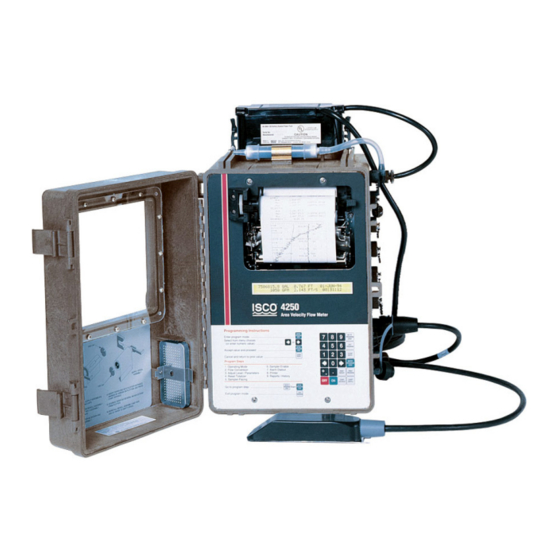
4250 Flow Meter Section 1 Introduction This section of the instruction manual provides a general intro- duction to the 4250 Area Velocity Flow Meter. It includes a description of the flow meter, an explanation of how the unit operates, and technical specifications. -
Page 14: Description
You need only enter the dimensions of the flow channel. If you want, you can also use the 4250 with a primary measuring device, as it has built-in standard level-to-flow conversions that cover most open channel flow measurement situations. -
Page 15: Flow Meter Operation
An internal plotter pro- vides a hard copy printout of the information computed, plots level or flow rate, and generates reports. Connectors for other equipment used with the 4250 are on the right side of the flow meter’s case. 1.4 Area Velocity Sensor... -
Page 16: Pressure Transducer Operation
1.5 Three Sensors Teledyne Isco offers three types of AV sensor for use with the 4250. The 10-foot standard unit is intended for operation in Available depths from 1 inch to 10 feet maximum. -
Page 17: Operation Of The Area Velocity Sensor
4250 Flow Meter Section 1 Introduction The third type of area-velocity sensor is the low-profile probe. This probe is streamlined for use in shallow flows and small pipes, in depths as low as 1 inch (25 mm). The area-velocity sensor is designed to avoid accumulating debris that could affect readings. -
Page 18: Software Upgrades
Refer to Figure 1-5 for a view of the connectors and their pin functions. 1.8 Technical The technical specifications for the 4250 Flow Meter are found in Tables 1-2, 1-3, and 1-4. The anticipated longevity for a roll of Specifications paper used in the internal plotter is shown for various chart speeds in Table 1-5. - Page 19 E = Channel 3 (-) Black Temp (+) F = Channel 2 (+) Blue Switched 12V Input Signal (-) Ground Level (+) Area Velocity Level (-) Probe Rcv (-) Rcv (+) Xmit (+) Xmit (-) Figure 1-5 4250 Side View Showing Connectors and Pin Functions...
- Page 20 4250 Flow Meter Section 1 Introduction Table 1-1 4250 Controls, Indicators, and Connectors CONTROLS SETTINGS FUNCTION ON/OFF On - Off Turns the flow meter on and off. Internal memory is protected with a standby battery. See Section 2. Keypad Momentary 24-key.
- Page 21 4250 Flow Meter Section 1 Introduction Table 1-2 4250 Technical Specifications Display Type 2-line, 40 character/line alphanumeric dot matrix liquid crystal. Power 12 to 14 VDC; 14 mA average at 12.5 VDC (printer set at 1" per hour, 1 minute level reading interval, 5 minute velocity reading interval.)
-
Page 22: Technical Specifications For The Standard Av Sensor
4250 Flow Meter Section 1 Introduction Table 1-3 Technical Specifications for the Standard AV Sensor Weight Standard Range 2.1 lbs (.96 kg) Extended Range 3.9 lbs (1.8 kg) Sensor Dimensions Length: 6.6 inches (6.8 cm) Width: 1.6 inches (4.1 cm) Height: 1.2 inches (3.0 cm) -
Page 23: Technical Specifications For The Low Profile Av Sensor
4250 Flow Meter Section 1 Introduction Table 1-4 Technical Specifications for the Low Profile AV Sensor Weight 2.1 lbs (.95 kg) including cable and connector Sensor Dimensions Length: 6.00 inches (15.2 cm) Width: 1.31 inches (3.3 cm) Height: 0.75 inches (1.9 cm) Nose Angle 110°... -
Page 24: Battery Life Expectancy
4250 Flow Meter Section 1 Introduction Table 1-5 4250 Chart Longevity Note Report Generator is turned off. Chart Speed, Inch/Hour Time to Empty Roll Days Days 29 Days 58 Days Table 1-6 Battery Life Expectancy Flow Meter Settings Minimum Maximum... -
Page 25: How To Make Battery Calculations
4250 Flow Meter Section 1 Introduction 1.9 How to Make Battery To calculate battery life expectancy for an installation, you must know two things: Calculations • The capacity of the battery you are using • The average current draw of the flow meter or (other device) powered. -
Page 26: Calculating Current Draw
Always operate these batteries with a reserve factor. 1.9.1 Calculating Current Calculating current draw for a 4250 Flow Meter is somewhat Draw more difficult than calculating the battery capacity. You cannot simply measure the idle current of the unit unless the printer and report generator are turned off in the program. -
Page 27: Measuring Flow Meter Current
4250 Flow Meter Section 1 Introduction ® Fluke (or other current- averaging meter) FLUKE 87 TRUE RMS MULTIMETER 00 I 5 Flow Meter Connect Cable 60-1394-023, or you can make mA A V your own. lead – Battery, 12 Volt... - Page 28 4250 Flow Meter Section 1 Introduction 1-16...
-
Page 29: Section 2 Programming
4250 Flow Meter Section 2 Programming 2.1 Getting Started You must program the 4250 Flow Meter to accurately monitor a flow stream. You must also install the area-velocity sensor. The 4250 will usually also need a primary measuring device, a structure placed across a stream that regulates flow. -
Page 30: Keypad Functions
4250 Flow Meter Section 2 Programming condition means that the flow meter will enable the sampler only when a certain condition or set of conditions, sensed by the flow meter, are met.) Total Flow Current Level Date (or pH/D.O.) Flow Rate Time (temperature) Following is a typical programming display on the flow meter. -
Page 31: Programming Procedure
4250 Flow Meter Section 2 Programming Print Program - Pressing this key will make the flow meter print out a complete list of the current program choices retained in memory. Print Report - One function of the flow meter is to print reports of all recorded activity at regular intervals. - Page 32 4250 Flow Meter Section 2 Programming If you want a different choice from the one that is flashing, you can move across the display by using the left and right arrow keys. Each time you press the right arrow key, the flashing selection will move one position to the right.
-
Page 33: Description Of Program Steps
2.3.2 Step 2, Flow Step 2, Flow Conversion Type, determines how the flow Conversion Type meter calculates flow rate and total flow. In general flow is calcu- lated for the 4250 from measured level, the size and shape of the... - Page 34 The 4250 uses this combination of measured level, velocity, and the dimension of the channel to calculate flow.
-
Page 35: Step 3 - Adjust Level, Parameters
19th-century Irish civil engineer. There is no primary measuring device as such. Instead the pipe, with considerations for its slope and internal roughness, serves as the primary device. The 4250 Flow Meter can calculate flow in round pipes, rectangular, U-shaped, or trapezoidal channels based on this formula. -
Page 36: Step 4 - Reset Totalizer
It is intended for use in research, assessment, and regulatory compliance. The sonde attaches to the modified RAIN GAUGE connector on the 4250. Flow meters having only a 4-pin rain gauge connector will not support the YSI Sonde. If you wish to upgrade your flow meter to use this system, contact the factory. -
Page 37: Step 5 - Sampler Pacing
Flowlink. Flowlink is Teledyne Isco’s proprietary data acquisition and management software. Flowlink works with personal computers, modems, and laptop computers to monitor flow meters from a distance. -
Page 38: Step 7 - Alarm Dialout Mode
2.3.8 Step 8 - Printer All 4250 Flow Meters have a built-in printer. The printer is more than just a printer, as it is capable of plotting linear data along with printing alphanumeric (letters and numbers) messages. In this step you set the speed for the chart to advance, from "... -
Page 39: Step 9 - Reports/History
50 history items and 200 sample events at a time. 2.4 Interpreting the Following are the program screens as they appear on the display of a 4250 Flow Meter. Explanations of most of the screens will be Program Screens provided. - Page 40 4250 Flow Meter Section 2 Programming If you press the right arrow key, the following options will appear in this order on the display: SETUP OPTIONS: 'EXIT' TO QUIT • STATUS ENABLE/ALARM HYSTERESIS • SETUP OPTIONS: 'EXIT' TO QUIT • OPTIONAL OUTPUTS • • REPORT SETUP •...
- Page 41 4250 Flow Meter Section 2 Programming DO/PH READING INTERVAL refers to the measurement of spe- cific aspects of the flow stream other than amount. 4250 Flow Meters support measurement of three different characteristics: temperature, pH (the relative acidity or alkalinity of a solution), and D.O., dissolved oxygen.
- Page 42 4250 Flow Meter Section 2 Programming When the level of the flow stream falls below the Minimum Depth, the flow meter approximates the velocity readings using velocity readings taken earlier, when depths were greater than the minimum. Under these conditions, the flow meter will not be able to detect the direction of the flow in the channel.
- Page 43 • YES • • NO • When the 4250 flow meter cannot obtain a valid flow mea- surement, it will report an error. This option tells the 4250 how to respond to an error measurement. The object is to select the option that gives you the greatest overall accuracy.
- Page 44 After selecting the appropriate parameter reading interval, press Enter. The Setup menu will reappear. This time, select STATUS from the Setup menu. Press Enter. The following will appear: MODEL 4250 HW REV: XXXXXX SW REV X.XX ID XXXXXXXXXXX HW REV refers to the hardware revision number.
- Page 45 4250 Flow Meter Section 2 Programming If there is a number greater than zero displayed for signal strength, the following is generally indicated: 1 = a very weak return signal; 100 = a very strong return signal. Numbers from 10 to 90 are normal, and numbers of 50 to 90 are typical for sewers.
- Page 46 4250 Flow Meter Section 2 Programming condition (or set of conditions) that must occur before the sampler is enabled. You enter a value (level is an example) that must be met before the enabling occurs. But what if this value is met and then falls away? It is possible for a condition to vary rapidly over a narrow range.
-
Page 47: Optional Outputs
10-50 mA (not supported by the flow meter). Teledyne Isco offers two different arrangements for the 4-20 mA control circuit. You can have either or both with the same flow meter. - Page 48 16 mA, whether activated or not. While 4-20 mA applications are generally made in installations with com- mercial power available, Teledyne Isco suggests the following for those who have a 4-20 mA output in a battery-powered installation.
- Page 49 4250 Flow Meter Section 2 Programming MANUAL CONTROL will appear if you continue moving to the right. “RANGE” will appear with the ANALOG OUTPUT menu if the optional internal 4-20 mA converter is present in the flow meter. If you select RANGE, the following will appear: OUTPUT RANGE •...
- Page 50 The information in the following section is provided for those who can write their own software programs to process the data transmitted from the Serial Output port. Special cables may be required. Contact Teledyne Isco technical support for more information. Serial Output – Returning to the OPTIONAL OUTPUTS menu, you will see the SERIAL OUTPUt option.
- Page 51 4250 Flow Meter Section 2 Programming Table 2-1 ASCII Output Codes (Continued) Code Parameter Units YSI 600Temperature Degrees Celsius YSI 600 Specific Conductance Millisiemens per centimeter YCO YSI 600 Conductance Millisiemens per centimeter YSI 600 Total Salinity Parts per thousand...
- Page 52 4250 Flow Meter Section 2 Programming If you select SERIAL OUTPUT from the OPTIONAL OUTPUTS menu, the following display will appear: PERIODIC SERIAL OUTPUT • ON • • OFF Selection of OFF from this menu will disable this feature, and there will be no further references to it.
- Page 53 4250 Flow Meter Section 2 Programming This step lets you determine the contents of the reports gen- erated by the flow meter. The flow meter’s report generator is capable of creating two different reports (A and B) that can be identical or quite different.
- Page 54 4250 Flow Meter Section 2 Programming Select YES if you want TEMPERATURE to appear in the report. Press Enter again and the display will return to the REPORT SETUP menu: REPORT SETUP • FLOW • • DO/PH • • YSI 600 • • SAMPLE HISTORY •...
- Page 55 ON if you need to lock the program. At that, we suggest using the lock only if there are compelling security reasons. Further changes will require entry of the password, which is the model number of the flow meter: 4250. If you select ON, there is a time-out before the lock engages. 2-27...
-
Page 56: Step 1 - Program
4250 Flow Meter Section 2 Programming If you continue to work through the rest of the program, the lock will not engage until you are done. But if you stop programming longer than two minutes, the lock will engage, and you will not be able to make any further program changes. - Page 57 4250 Flow Meter Section 2 Programming GPS = gallons per second; GPM = gallons per minute; GPH = gallons per hour; MGD = millions of gallons per day; CFS = cubic feet per second; CFM = cubic feet per minute; CFH = cubic feet per hour;...
- Page 58 4250 Flow Meter Section 2 Programming RAIN GAUGE • INCHES • • MM • • NOT MEASURED • You must have an Isco 674 Rain Gauge (or approved equiv- alent) connected to the flow meter through the Rain Gauge Port to sense rainfall. MM = millimeters. The rain gauge is factory-calibrated.
- Page 59 YSI 600 Multi-Parameter Sonde. This probe allows you to measure several different characteristics of a flow stream at the same time. The YSI 600 Sonde attaches to the Rain Gauge con- nector on the 4250. This connector must be a special, modified connector with nine pins. Note 4250 Flow Meters with 4-pin Rain Gauge connectors cannot support the YSI 600.
- Page 60 4250 Flow Meter Section 2 Programming CAUTION Do not disconnect either sonde or flow meter power during a communications check. The memory in the sonde can be dam- aged by a power failure during an update. If the communication check is bad, the following display will...
-
Page 61: Step 2 - Flow Conversion (Area Velocity Only)
If you wish to use the 4250 with a primary measuring device, skip to Step 2 - Flow Conversion (Level-to-Flow Rate) fol- lowing this section. - Page 62 • ONE • • TWO • • THREE • • FOUR • • (NONE) • In general, the option of NONE will not show up on the display. For the 4250, you can define the four sets of data points as either level-to-flow rate data points or level-to-area data points.
- Page 63 4250 Flow Meter Section 2 Programming To get out of this situation, you would have to exit and then go back to the menu where you defined the data points as level-to-flow rate data points. When you reach that menu you would select CLEAR to erase the set in the flow meter’s memory.
-
Page 64: Step 2 - Flow Conversion (Level-To-Flow Rate)
N o r m a l l y, t h e 4 2 5 0 i s u s e d i n (Level-to-Flow Rate) area-velocity installations. This selection allows you to use the 4250 with a primary measuring device, Manning applications, a custom flow equation, or data points. FLOW CONVERSION TYPE •... - Page 65 4250 Flow Meter Section 2 Programming at the calibration point are essential for accurate flow calculation by the flow meter. If you select WEIR, the following display will appear: SELECT TYPE OF WEIR: • V-NOTCH • • RECTANGULAR • • CIPOLLETTI •...
- Page 66 4250 Flow Meter Section 2 Programming If you press the right arrow key several times, the sizes shown below will move onto the screen: SELECT PALMER-BOWLUS SIZE • 24" • • 27" • • 30" • • 48" • If you select LEOPOLD-LAGCO, this will appear: LEOPOLD-LAGCO FLUME SIZE •...
- Page 67 4250 Flow Meter Section 2 Programming Returning to Step 2, SELECT FLOW CONVERSION, if you select MANNING, the following will appear: SELECT MANNING TYPE • ROUND PIPE • • U-CHANNEL, RECTANGULAR • • T– TRAPEZOIDAL is also available, if you move to the right with the right arrow key.
- Page 68 4250 Flow Meter Section 2 Programming (Slope and roughness are entered the same as for ROUND PIPE previously.) Then: MANNING RECTANGULAR WIDTH=X.XXX FEET (or meters) If you select TRAPEZOID for the Manning flow conversion, the following displays will appear: MANNING TRAPEZOID SLOPE=X.XXXXX ROUGH=X.XXX...
- Page 69 Section 2 Programming DATA POINT flow conversion allows you to enter measured level and flow rate values for a number of different points. The 4250 Flow Meter can accept up to four sets of data points with each set containing as many as fifty points.
- Page 70 4250 Flow Meter Section 2 Programming Enter Maximum Head Before advancing from step 2 (Flow Conversion) to step 3 (Adjust Parameters), the flow meter will request that you enter a value for Maximum Head (Level) for the device or flow con- version you are using.
-
Page 71: Step 3 - Parameter To Adjust
4250 Flow Meter Section 2 Programming or C for temperature, mg/L for dissolved oxygen, etc. After you have set the minimum value for the port, the flow meter will request you to enter a value for full-scale, or 100%: ANALOG OUTPUT PORT 1 20 MA = X.X (units) - Page 72 4250 Flow Meter Section 2 Programming This picture shows you how D – d = h (level) to measure level. You then enter this value with the number keys. Note that must LEVEL ADJUST done at the job site, while most other programming can be done in the shop.
- Page 73 4250 Flow Meter Section 2 Programming probably select pH 4 & 7. If the pH is generally above 7, you would probably select pH 7 & 10. If your stream’s pH varies a great deal, say from 3 to 12, your best choice would be pH 4, 7, &...
- Page 74 4250 Flow Meter Section 2 Programming Select the appropriate units and press Enter. ALTITUDE ALTITUDE = X.XX FT (or meters) Enter the altitude for your location. Then: WRAP D. O. PROBE IN MOIST CLOTH PRESS ENTER WHEN STABLE: X.XXX MG/L For more detailed information on the pH and D.
- Page 75 4250 Flow Meter Section 2 Programming If you select CONDUCTIVITY for the parameter to calibrate, the following display will appear: CONDUCTIVITY CALIBRATION UNITS • MS/CM • • PPT • MS/CM is milli-siemens per centimeter. The siemen is the S.I. (Système Internationale) name for the unit of conductance, which is also the reciprocal of the ohm.
-
Page 76: Ysi 600 Sonde Calibration Flow Chart
4250 Flow Meter Section 2 Programming Figure 2-5 YSI 600 Sonde Calibration Flow Chart 2-48... -
Page 77: Step 4 - Reset Totalizer
All models have the capability of maintaining a separate totalizer for the time the sampler is enabled through the sampler enabling feature (step 6). The 4250 flow meter, because it can measure forward and reverse flows, maintains three separate totalizers: a separate totalizer for each direction and a totalizer for the difference between forward and reverse flows. - Page 78 4250 Flow Meter Section 2 Programming will also cause the flow meter to advance to the next Program step. If you select VOLUME for sampler pacing, the following will appear: SAMPLER PACING ENTER PACING VOLUME XX.XXXX CF • Other units of measure may appear here. The range for pacing is max.
- Page 79 4250 Flow Meter Section 2 Programming For any of these conditions, you can set the point at which change in the selected condition causes the flow meter to send a flow pulse to the sampler. The following menu will appear: (Selected CONDITION) •...
-
Page 80: Step 6 - Sampler Enable
4250 Flow Meter Section 2 Programming Then: CONDITION FALSE PACING INTERVAL PACE EVERY X MINUTES This option allows you to send flow pulses periodically to the sampler during the time the conditions you established for sampler pacing are not being met. Again, entering 0 sends no pulses. - Page 81 4250 Flow Meter Section 2 Programming If you press the right arrow key several times, the following times will appear: RAINFALL TIME PERIOD • 6 HR • • 8 HR • • 12 HR • • 24 HR • • 48 HR • • 72 HR •...
- Page 82 4250 Flow Meter Section 2 Programming After you have determined what condition will signal the sampler and under what circumstances, the following menu will appear: SELECT OPERATOR • DONE • • OR • • AND • This step allows you to trigger the sampler from a single con- dition or from two conditions.
-
Page 83: Step 7 - Alarm Dialout Mode
4250 Flow Meter Section 2 Programming Select YES to reset the sampler enable feature; select NO to leave the sampler enabled. PRINTER ON/OFF WITH ENABLE • YES • • NO • This selection allows you to turn the flow meter’s internal printer on or off when the sampler is enabled from the flow meter. - Page 84 4250 Flow Meter Section 2 Programming The intervals above are the periods of time over which the rainfall occurs. The amount of rain entered in the previous step and detected by the rain gauge must fall during the time interval chosen from this menu before the flow meter recognizes the event as a storm.
-
Page 85: Step 8 - Printer
4250 Flow Meter Section 2 Programming The flow meter will then request that you enter the telephone numbers for the remote alarms. There are five possible telephone numbers, in decreasing order of importance. You can enter as many as eighteen digits for each phone, so the remote targets need not necessarily be local. - Page 86 4250 Flow Meter Section 2 Programming Program selections made in this step will determine the appearance of the printer/printer’s chart. The first menu will request the speed of the chart. ENTER PRINTER SPEED • OFF • • 1/2"/HR • • 1"/HR • • 2"/HR • • 4"/HR •...
-
Page 87: Step 9 - Reports/History
4250 Flow Meter Section 2 Programming that you enter the full-scale value for the condition being plotted. For example, if you selected LEVEL as a condition, the following would appear: PRINTER LINE A FULL SCALE X.XXXX FEET (or other units of measure, as selected) The flow meter automatically goes into over-range if the data goes higher than the full-scale value you have selected. - Page 88 4250 Flow Meter Section 2 Programming If you select OFF, the program will advance to the next step, and there will be no report A generated. If you select YES, the fol- lowing will appear: REPORT A DURATION TO BE IN •...
-
Page 89: Flow Meter History Contents
4250 Flow Meter Section 2 Programming The final step on the flow meter is FLOW METER HISTORY. This step presents a record of the programming activity on the flow meter that you can have printed on the printer. The flow meter keeps a record of certain programming changes and prints them out. - Page 90 4250 Flow Meter Section 2 Programming 2-62...
-
Page 91: Section 3 Installation
4250 Flow Meter Section 3 Installation This section of the manual contains information on installing the 4250 Flow Meter. Included are sections on power sources, mounting methods, interconnection wiring, installation of the AV sensor and setup procedure for the unit. - Page 92 If you suspect blockage in the AV sensor’s reference tube, return the probe to Teledyne Isco. The repair department may be able to vacuum the water or blockage from the line;...
-
Page 93: Opening The Case
(Note that you must be using FLOWLINK software for any data to accumulate in memory.) 3.2.2 Isco Sampler If you combine a 4250 Flow Meter with an Isco Wastewater Sampler in a flow-paced sampling system, you can power the flow meter from the sampler’s power supply. Connect the flow meter to the sampler with the Isco flow meter-to-sampler cable. -
Page 94: Isco Nickel-Cadmium Battery
3.2.3 Isco Nickel-Cadmium Teledyne Isco offers a 4 ampere-hour 12-volt rechargeable Battery nickel-cadmium battery pack to power the flow meter. Teledyne Isco packages this battery specifically for use with Isco flow meters and samplers. Refer to the Power Products Guide accom- panying this manual for detailed information about this battery and the procedure for charging it. -
Page 95: Isco Lead-Acid Battery
3.2.5 AC Power Supplies Teledyne Isco also offers two different AC power supplies, the High Capacity Power Pack and the Battery-Backed Power Pack, to power the flow meter. These power supplies are designed for operation from 120 Volts AC, 50/60 Hz commercial power sources. -
Page 96: External 12 Volt Direct Current Source
However, you will have to mount batteries of this type externally, as they are too large to fit on top of the flow meter. Teledyne Isco offers a special optional connect cable to power the flow meter from a separate battery. -
Page 97: Flow Meter Mounting And Installation
4250 Flow Meter Section 3 Installation 3.3 Flow Meter Mounting The 4250 Flow Meter is a portable device; you may install it per- manently or temporarily. You can suspend the flow meter in tem- and Installation porary installations, such as sewers, or mount it permanently in other installations, such as treatment plants, at your option. -
Page 98: Vent Hose To Desiccant Cartridge
Then slip the handle through the suspension bracket. Figure 3-3 4250 Suspended by Handle (handles may vary) 3.3.4 Vent Hose to Desiccant If you suspend the flow meter above the flow stream and there is... -
Page 99: Quick-Disconnect Box
Figure 3-4 Quick-Disconnect Box for the Area Velocity Sensor To use the Quick-Disconnect box, you will need a cable of the correct length with an M/S connector to plug into the flow meter. Teledyne Isco will build the cable with the proper connector on one end and stripped wires on the other end as a special order. - Page 100 Section 3 Installation Figure 3-5 Cable Connections in the Quick-Disconnect Box The wire colors shown are for the Teledyne Isco-supplied custom cable. You must use the Isco cable because the connector at the flow meter end of the cable is special and not available else- where.
-
Page 101: Extension Cables
This tube is vented through the connector into the cabinet of the 4250. From there, it is vented to the atmo- sphere through a desiccant cartridge mounted on the side of either the flow meter or the Quick-Disconnect Box. -
Page 102: Area Velocity Sensor Installation
Shallower streams should be measured using the low-profile AV sensor. Streams that run consistently below one inch are not a good application for the 4250. • Velocity measurements depend on the presence of some particles in the water, either air bubbles or suspended solids. -
Page 103: Level Measurement In Open Channels (No Primary Device)
4250 Flow Meter Section 3 Installation Although the sensor is easiest to calibrate when located at the bottom of the stream, you can locate it off-center in a larger pipe, if there are good reasons to do so. Streams that have large amounts of silt would be suitable for this. - Page 104 4250 Flow Meter Section 3 Installation A-V Sensor Ultrasonic Cone Channel center line Effect of offset mounting of sensor (Top view of channel) In such cases, make sure you measure depth at a point inside the cone. In large channels, you may have to measure several feet upstream from the sensor.
- Page 105 4250 Flow Meter Section 3 Installation The flow in this 10" round pipe is uni- Sensor Cable (Note routing) form. The ideal level measurement point is always within the ultrasonic Sensor Mounting Ring cone – point C, but it is not easily...
-
Page 106: Rectangular And Trapezoidal Channels
These mounting rings are available for use in pipes with inside diameters of 6" (15.2 cm), 8" (20.3 cm), 10" (25.4 cm), 12" (30.5 cm), and 15" (38.1 cm). The Teledyne Isco part numbers for the various size mounting rings available are listed in Appendix B. - Page 107 4250 Flow Meter Section 3 Installation Compress ring into gap to install in pipe, then..outward force of ring against pipe wall holds ring in place inside pipe. Figure 3-9 Sensor Installed on a Spring Ring CAUTION Make sure the slots on the sensor are completely pressed onto the tabs on the ring.
-
Page 108: Scissors Rings
3.8.2 Scissors Rings For pipes larger than 15" in diameter, Teledyne Isco offers the adjustable Scissors Ring (also known as the Universal Mounting Ring). This device consists of two or more metal strips that lock together with tabs to form a single assembly. -
Page 109: Completing The Av Sensor Installation
4250 Flow Meter Section 3 Installation Scissors Assembly Extensions Base Section Tightening the scissors assembly expands the ring to press firmly against the pipe wall, securing the ring. Figure 3-10 Scissors Ring Adjustment Mounting ring kits are available for different pipe sizes. A kit is also available for partial pipe applications (consult your Isco Mounting Rings Installation and Operation Guide). -
Page 110: Sampler Interface
Section 3 Installation 3.9 Sampler Interface One of the uses of the 4250 Flow Meter is to control a sampler in a flow-paced sampling mode. Flow-paced sampling means that the flow meter is programmed to signal the sampler to take a sample after a specific volume of flow has passed through the flow stream, rather than after a particular period of time. -
Page 111: Section 4 Options And Accessories
4200 Series Flow Meter. Application-specific options are covered in the Installation sections of each type of flow meter. Teledyne Isco offers the following options for use with all 4200 series flow meters: • 4200T Modems •... -
Page 112: Modems And Flowlink Software
Disconnect the interroga- tor cable in order to use the 4200T Modem. 4.1.2 Modems and Flowlink The 4200T Modem communicates with Teledyne Isco’s Flowlink Software data storage and acquisition software, setting up the flow meter to collect blocks of data. -
Page 113: Types Of Service
“If trouble is experienced with this equipment, please contact the Teledyne Isco Customer Service Department, (800) 228-4373 or, outside the U.S.A., call (402) 464-0231, for repair and (or) warranty information. If the trouble is... -
Page 114: Connection To External Serial Device
This option (SERIAL OUTPUT) is discussed in detail in Section 2. Teledyne Isco offers a 300 baud output on the RAIN GAUGE con- nector. This port provides ASCII level and flow rate data for remote transmission to any ASCII-compatible equipment. Every... -
Page 115: External 4-20 Ma Output Interface
4250 Flow Meter Section 4 Options and Accessories outputs. One is an external box that converts the signals from the flow meter to a 4-20 mA current loop. The other is an internal circuit board containing three separate analog output circuits on the same board. -
Page 116: Internal Multiple Analog Output Board
4250 Flow Meter Section 4 Options and Accessories 4.3.2 Internal Multiple For those needing more than one analog output, Teledyne Isco Analog Output Board offers the Multiple Analog Output Board, which is installed inside the flow meter. This board provides three isolated analog outputs. - Page 117 4250 Flow Meter Section 4 Options and Accessories Table 4-2 Multiple Analog Output Board Specifications Operating Temperature 0 to 140° F (–18 to 60° C) 0.5% of full-scale Output Accuracy Resolution 0.1% of full-scale (0-20 mA) Electrical Isolation Isolated from each other and from the flow meter.
-
Page 118: Pacing Non-Isco Equipment
For applications requiring the conversion of the flow meter’s flow proportional output signal to a fixed duration contact closure, Equipment Teledyne Isco offers the Type ‘E’ Interface. Figure 4-1 Type ‘E’ Interface for pacing non-Isco equipment To allow connection to a second device simultaneously, you must connect using the special Isco Y cable, part #60-5314-278. - Page 119 4250 Flow Meter Section 4 Options and Accessories CAUTION Always protect your equipment by observing anti-static precau- t i o n s w h e n ex p o s i n g i n t e r n a l c o m p o n e n t s . Tu r n t o Section 5.7.1 for recommended precautions.
- Page 120 4250 Flow Meter Section 4 Options and Accessories Figure 4-3 Removing the lower shield 3. In the lower right hand corner of the power supply PCB, disconnect the red wire’s spade connector from J3 and con- nect it to J1.
-
Page 121: Tipping Bucket Rain Gauge
4250 Flow Meter Section 4 Options and Accessories 4.5 Tipping Bucket Rain A Tipping Bucket Rain Gauge is available from Teledyne Isco for use with 4200 Series Flow Meters. The gauge connects to the Gauge flow meter by a cable terminated in an M/S connector. This con- nector plugs into the Remote Printer/Rain Gauge connector on the case. -
Page 122: Isco Flowlink Software
Flowlink Software is available from its manual or from the factory. 4.7 High-Low Alarm Relay Teledyne Isco offers a control box that monitors flow rate data available from any 4200 Series Flow Meter. Alarm relays trip when the flow rate exceeds or falls below pre-selected limits. -
Page 123: Installation
Flow Meter Meter requires a cable and an M/S connector. A special cable, 25 feet long, is available from Teledyne Isco. On one end of the cable is a 4-pin, male M/S connector. Plug this connector into the Remote Printer/Rain Gauge connector on the flow meter. The other end of the cable has 3 stripped wires. -
Page 124: Temperature Probe
4250 Flow Meter Section 4 Options and Accessories • The probe cable is carefully routed out of the stream. • Only the temperature probe can connect directly to the flow meter’s parameter probe connector. • The pH and D.O. probes both connect to parameter modules (amplifiers). -
Page 125: Ph Probe
4250 Flow Meter Section 4 Options and Accessories Figure 4-6 Temperature Probe 4.10 pH Probe The pH probe measures the acidity or alkalinity of an aqueous solution by determining the relative quantity of dissociated hydrogen ions, H (actually H ) in the solution. A larger... - Page 126 4250 Flow Meter Section 4 Options and Accessories Figure 4-7 pH Probe (with protective cap) The pH probe is a combination of two electrochemical half-cells. Together they provide a low-voltage signal that corresponds to the hydrogen-ion concentration of a solution. If you look at the pH probe, you will see a glass bulb on one end.
-
Page 127: Ph Probe Calibration
The flow meter determines the pH value and displays 4.10.1 pH Probe Calibration The 4250 provides a two- or three-point calibration for the pH probes with commercially-prepared calibrated buffer solutions. Calibrations of 4 and 7, 7 and 10, and 4, 7, and 10 are all possible. -
Page 128: Ph Probe Installation Guidelines
4250 Flow Meter Section 4 Options and Accessories RINSE PROBE AND PLACE IN 7.0 pH SOLUTION PRESS ENTER WHEN STABLE: X.XX pH When you have entered this second value, the pH probe calibration is complete. You can then install the probe in the flow stream. - Page 129 4250 Flow Meter Section 4 Options and Accessories The mounting rings are held in place by the outward force of spring pressure in the smaller sizes and by a screw arrangement in the larger sizes. After mounting the probe in the ring or strap, route the cable out of the stream so it will not trap debris that could clog the sewer.
-
Page 130: Storage And Maintenance Of Ph Probes
5 minutes. You can mount the probe facing either upstream or downstream, but Teledyne Isco recommends facing upstream, as there is a stop on the sensor carrier that is not effective when the probe is facing downstream. Remember to unscrew the rubber guard cap from the sensing end of the probe when you install it, or the probe will be unable to sense the flow stream. -
Page 131: Dissolved Oxygen (D.o.) Probe
4250 Flow Meter Section 4 Options and Accessories The pH sensitive glass can also become “conditioned” to its envi- ronment, especially when it is continuously exposed to high pH (10 and above) solutions. The glass does have a memory and will respond slowly when exposed to a lower pH solution after having been in a high pH solution for any significant period of time. -
Page 132: How The D.o. Probe Works
• Frequent maintenance is necessary when the probe is installed in flows with grease or solids content. Tests conducted by Teledyne Isco with probes installed in various waste streams have indicated that greases and solids quickly coat the probe’s membrane, making it impossible for oxygen to enter the reaction chamber. -
Page 133: Probe Preparation
Place a piece of moist tissue inside the bottle, and slide the bottle over the probe. 4.11.3 Membrane Teledyne Isco supplies a 2 mil (.002") thick membrane for use Thicknesses with the D.O. probe. This membrane is recommended for long-term monitoring situations only, typical of our users’... -
Page 134: Probe Installation
4250 Flow Meter Section 4 Options and Accessories cations. Use only this thickness membrane with D.O. probes con- nected to Isco flow meters. Do not use other thickness of membranes as the Parameter Module used with the probe is cali- brated only for the 2-mil membrane, and cannot be recalibrated in the field. - Page 135 (which can result from extended use with a loose or wrinkled membrane), you need to restore its surface. You can return it to Teledyne Isco or clean it yourself with a probe reconditioning kit. (This kit is available from Teledyne Isco.) Never use chemicals or any abrasive not supplied with this kit.
-
Page 136: Calibrating The D.o. Probe With A Flow Meter
4250 Flow Meter Section 4 Options and Accessories Figure 4-10 D.O. Parameter Module You must use the Isco 270 D.O. Module box between the probe and flow meter; this extends the distance between the probe and the flow meter to 1,000 feet. -
Page 137: Installation Of Parameter Probes In Mounting Rings
4250 Flow Meter Section 4 Options and Accessories Altitude is just off the screen. You can select D.O. STANDARD if this calibration medium is available to you. Do not select ABS (absolute) BAROMETRIC PRESSURE unless you are at sea level or know how to correct for this value. The barometric pressure provided from the Weather Bureau is corrected for altitude. -
Page 138: The Ysi 600 Multiple Sensor Sonde
4250 Flow Meter Section 4 Options and Accessories Cover removed Temperature to show sensors pH sensor pH reference Conductivity (Inside) D.O. sensor End view, facing sensors Figure 4-11 The YSI 600 Multiple Sensor Sonde The YSI 600 is ideal for profiling and monitoring water condi- tions in industrial and wastewater effluents, lakes, rivers, wet- lands, estuaries, coastal waters, and monitoring wells. -
Page 139: Mechanical Totalizer
4250 Flow Meter Section 4 Options and Accessories 4.14 Mechanical Totalizer A mechanical totalizer is available for the 4250 that consists of a seven-digit, non-resettable mechanical counter mounted in the front panel. It must be ordered with the flow meter. The totalizer advances according to program selections for units of measure and the maximum flow of the primary device used. - Page 140 4250 Flow Meter Section 4 Options and Accessories 4-30...
-
Page 141: Section 5 Maintenance And Service
CMOS circuitry. Teledyne Isco recommends that you become familiar with the maintenance procedures presented here. While the 4250 is rug- gedly built to withstand severe field conditions, it will function best and remain most reliable if you follow these simple proce- dures. -
Page 142: Reactivation Of The Desiccators
4250 Flow Meter Section 5 Maintenance and Service 5.2 Reactivation of the The 4250 has a reusable desiccant canister held by a steel clamp on the inside of the case lid. There is also a tubular desiccant car- Desiccators tridge on the top of the case next to the connectors. The canister contains silica gel that adsorbs moisture trapped inside the flow meter’s case when it is closed. -
Page 143: Regenerating The Desiccant Canister
4250 Flow Meter Section 5 Maintenance and Service well ventilated room. DO NOT use a microwave oven to recharge the desiccant car- tridge. Heating the metal cartridge case in a microwave oven will damage the oven. Leave the room while heating the desiccant. - Page 144 4250 Flow Meter Section 5 Maintenance and Service CAUTION There have been reports of irritating fumes coming from the desiccant during regeneration. While our attempts to duplicate the problem have been unsuccessful, we still urge you to use caution. • Use a vented oven in a well-ventilated room.
-
Page 145: Care Of The Av Sensor And Cables
The pressure trans- ducer is behind this disk. In general, it should not be necessary to remove this disk, and Teledyne Isco strongly recommends that you do not. In the standard AV sensors, removing the plate will expose the paper-thin diaphragm of the transducer. -
Page 146: Cleaning The Low Profile Av Probe
4250 Flow Meter Section 5 Maintenance and Service spacer disk between the the sensor mounting plate and the screw at the front of the sensor. 4. Flush the underside of the sensor with water. Do not remove the protective disk and round gasket from the level sensor unless you can see that the ports are blocked with solids. -
Page 147: Cable Inspection
4250 Flow Meter Section 5 Maintenance and Service Figure 5-5 Low Profile Probe With Transducer Housing Revealed 5.3.4 Cable Inspection Periodically inspect the AV sensor cable for wear caused by abuse or exposure to the elements. Damaged cables can affect the oper- ation of the probe, particularly if the reference port vent tube inside the cable is collapsed or blocked. -
Page 148: Maintenance Of The Printer
4250 Flow Meter Section 5 Maintenance and Service 5.4 Maintenance of the The internal printer needs little maintenance beyond changing the chart roll and the ink ribbon. Printer Refer to the pictures provided for each section. Also refer to the label inside the cabinet. - Page 149 4250 Flow Meter Section 5 Maintenance and Service 6. Remove the feed spool by pulling on the handle extending from the right side of the printer. 7. Snap off the other white end cap as described previously. Save the white end caps; you will reuse them.
-
Page 150: Ink Ribbon Replacement
4250 Flow Meter Section 5 Maintenance and Service SPOOL DETECTING LEVER SPOOL SHAFT PRINT HEAD Figure 5-7 Changing the Ink Ribbon 5.4.2 Ink Ribbon Ribbon life will vary greatly from one installation to another Replacement depending on how often the printer has to print. When the char- acters on the chart become difficult to read, you should replace the ribbon. -
Page 151: Do Not Disassemble Or Lubricate The Printer
Teledyne Isco recommends you make no attempt to oil or disas- semble the mechanism if it malfunctions. -
Page 152: Fuse Replacement
4250 Flow Meter Section 5 Maintenance and Service Note If you disassemble the flow meter for servicing, you will also remove the aluminum chassis covers to access the circuitry. Always replace these covers when repairs have been com- pleted. The covers protect the circuit boards and also reduce signal emissions that could interfere with the operation of nearby electronic equipment. -
Page 153: Display Warnings
CAUTION This procedure will cause most programmed entries and accu- mulated data stored in the 4250 to be lost, and the flow meter will revert to factory default settings. If this operation is per- formed, it will be necessary for you to reprogram the unit to meet the specifications of your installation. -
Page 154: Preliminary Troubleshooting Steps
Our Technical Service Department has trained technicians and specially designed equipment necessary for timely, efficient repair of the 4250 Flow Meter. If you still wish to attempt repairs, the Customer Service Department is available to provide additional advice and information on ser- vicing. - Page 155 Section 5 Maintenance and Service Following are suggested areas to check before attempting to service the 4250’s circuitry. Telephone consultation with Cus- tomer Service is strongly recommended. Look for the following: 1. Verify that the problem is in the flow meter and not caused...
-
Page 156: Precautions For Servicing Cmos Circuitry
4250 Flow Meter Section 5 Maintenance and Service 5.7 Precautions for Most of the circuitry in the 4250 Flow Meter is made up of CMOS components. Because of the oxide gate structure of these devices, Servicing CMOS they are extremely susceptible to destruction caused by the dis- Circuitry charge of static electricity through their inputs. - Page 157 4250 Flow Meter Section 5 Maintenance and Service unless the legs or leads are also stuck into a block of black conductive foam. If purchased replacement compo- nents do not come in marked, protective packaging, do not use them. They may already be destroyed.
-
Page 158: Software Updates
This application will transfer a binary file from your PC to the instrument's flash memory. Updated binary files are available from Teledyne Isco when enhancements have been made to the instrument software. Contact the factory for help with obtaining these files. -
Page 159: Appendix A Replacement Parts And Accessories
A.1 Replacement Parts The following section contains illustrations and corresponding tables of 4250 Flow Meter replacement parts. A list of accessories and optional equipment can be found at the end of this section. Replacement parts can be purchased by contacting Teledyne Isco’s Customer Service Department. - Page 160 4250 Flow Meter Appendix A Replacement Parts and Accessories...
- Page 161 4250 Flow Meter Appendix A Replacement Parts and Accessories...
-
Page 162: Replacement Parts List
Motor Assy Chart Drive 4200 60-3214-093 LCD Module Assy B/L 60-3224-070 Case Bottom Sub Assembly 60-3214-098 Keyboard PCB Assembly 60-3254-024 4250 CPU CBA w/ Software 60-3254-014 PCB Assembly 4250 Parameter/CPU 60-3214-120 Harness Assy - 12 VDC/Sampler 60-3214-122 Harness Assy - Interrogator 60-3214-140... - Page 163 4250 Flow Meter Appendix A Replacement Parts and Accessories Table A-1 Replacement Parts List (Continued) Part Number Complete Parts Description 202-4001-14 O-Ring Silicone #114 0.61ID × 0.1 W 202-4001-18 O-Ring Silicone #118 0.86 ID × 0.1 W 202-4001-20 O-Ring Silicone #120 0.99 ID × 0.1 W...
-
Page 164: Accessory/Options Parts List
4250 Flow Meter Appendix A Replacement Parts and Accessories A.2 Accessory/Options Parts List 4250 Flow Meter, Basic Unit, 68-4250-001 Includes: Area Velocity Sensor, 10 range (25 cable)................60-3254-001 4250 Flow Meter........................60-3254-009 Accessory Package ........................60-3254-011 Instruction Manual ........................60-3254-012 Pocket Guide .......................... - Page 165 4250 Flow Meter Appendix A Replacement Parts and Accessories pH Probe only ........................... 60-9004-126 D.O. Probe only ......................... 472-0000-00 D.O. Membrane Kit ........................479-0020-02 (Includes 30, 0.002" membranes, electrolyte, sanding tool, and disks) O-Ring Kit for D. O. Probe ....................... 479-0020-00 Temperature Probe only......................
- Page 166 4250 Flow Meter Appendix A Replacement Parts and Accessories...
-
Page 167: Appendix B Programming Worksheets
Appendix B Programming Worksheets Use this form to make a hard copy of the program you use in your 4250. Most program steps can be completed in the shop without the flow meter being installed or at the job site. However, please note the following: •... - Page 168 4250 Flow Meter Appendix B Programming Worksheets 8. Zero Level Offset = Feet (or Meters)_________ 9. Zero Flow on Error? Yes 10. D.O./ph Reading Interval: Continuous, 15 Sec, 30 Sec, 1Min, 2 Min, 5 Min______________________ 11. YSI 600 Reading Interval: Continuous, 15 Sec, 30 Sec, 1 Min, 2 Min, 5 Min_________________ 12.
-
Page 169: Flow Conversion: Area Velocity
4250 Flow Meter Appendix B Programming Worksheets 42. Sample History In Report: 43. Setup Options: Status, Report Setup, LCD Backlight 44. LCD Backlight Mode: Time-out, Continuous, Off 45. Language: English, French, German, Spanish 46. Program Lock: On, Off 47. Select Option: Program, Setup. This time, select Program and do the following (Program Section) 48. -
Page 170: Flow Conversion: Level-To-Flow Rate
4250 Flow Meter Appendix B Programming Worksheets 15. Set_____(1-4):______(1-50) Points Entered: (Use), Edit Point, Add Point, Clear, Print___________________ 16. Set_____(1-4) Data Point (1-50)____: Enter:__.___(level units)__.___(units of volume) Data Point Set Level Flow Level Flow Level Flow Level Flow B.3 Flow Conversion: 1. -
Page 171: Parameter To Adjust
2. (Job Site only) Enter Current Level: __.____ Ft (or M). Note: Installations generally use either the Teledyne Isco parameter probes or the YSI 600 Sonde, but not both. Use the following menus for either the Teledyne Isco probes or... -
Page 172: Reset Totalizer
4250 Flow Meter Appendix B Programming Worksheets the YSI 600 Sonde. Steps 3, 4, and 5 can be used for both 2 and 3-point pH calibrations. 3. Rinse Probe And Place In 4.0 pH Solution: Press Enter When Stable __.____ pH (job site only) 4. -
Page 173: Alarm Dialout Mode
4250 Flow Meter Appendix B Programming Worksheets 7. Level: Greater Than, Less Than, Rate Of Change 8. Level: Greater Than __.____ Feet (or meters) 9. Select Operator: Done, Or, And 10. Flow Rate: Greater Than, Less Than, Rate Of Change 11. - Page 174 4250 Flow Meter Appendix B Programming Worksheets 3. Enter Report A Duration: ______ Hours 4. Print Report A at Yr:_____Month:___Day:___Hr:___ Min:___ 5. Report Generator B: On, Off, (Print) 6. Report B Duration To Be In: Hours, Days, Months 7. Enter Report B Duration: ____Hours 8.
-
Page 175: Appendix C General Safety Procedures
The second section deals with the special problem of hazardous gases found in sewers. WARNING The 4250 Flow Meter has not been approved for use in hazardous locations as defined by the National Electrical Code. - Page 176 4250 Flow Meter Appendix C General Safety Procedures “Lifting Injuries. Unless proper tools are used to remove manhole covers, back injuries or injuries to hands or feet may result. “2. Planning. Advance planning should include arrangements for test equipment, tools, ventilating equipment, protective clothing, traffic warning devices, ladders, safety harness, and adequate number of personnel.
- Page 177 4250 Flow Meter Appendix C General Safety Procedures the manhole opening. To avoid a serious injury, a person should not be lifted out of a manhole by his arm unless it is a dire emer- gency. “When more than one person must enter a manhole, the first person should reach the bottom and step off the ladder before the next one starts down.
-
Page 178: Lethal Atmospheres In Sewers
4250 Flow Meter Appendix C General Safety Procedures “10. Field Equipment. The following equipment will be available for use: Blowers Gloves Traffic cones Breathing apparatus Hard Hats Coveralls Harnesses First aid kits Manhole irons Emergency flashers Pick axes Flashlights Rain slickers... - Page 179 4250 Flow Meter Appendix C General Safety Procedures “It seems unlikely that anyone has ever died in a sewer from suf- focation, that is, a lack of oxygen. Deaths have often been attributed to ‘asphyxiation.’ This is a word which, according to the dictionary, is used to mean death from an atmosphere that does not support life.
-
Page 180: Hazardous Gases
4250 Flow Meter Appendix C General Safety Procedures number of harmful vapors. They, too, are sensed by smell and explosimeter tests if they get into the public sewer. Such occur- rences are rare. “The attempt to instill a sense of urgency about real hazards is diluted if a man is told to give attention to a long list of things that in fact are irrelevant. - Page 181 4250 Flow Meter Appendix C General Safety Procedures Table C-1 Hazardous Gases (Continued) Specific Explosive Likely Max. Safe Simplest and Gravity Range (% by Location Most Chemical Common Physiological Safe 60 8 Hour Cheapest or Vapor vol. in air) Common...
- Page 182 4250 Flow Meter Appendix C General Safety Procedures Table C-1 Hazardous Gases (Continued) Specific Explosive Likely Max. Safe Simplest and Gravity Range (% by Location Most Chemical Common Physiological Safe 60 8 Hour Cheapest or Vapor vol. in air) Common...
- Page 183 4250 Flow Meter Appendix C General Safety Procedures Table C-1 Hazardous Gases (Continued) Specific Explosive Likely Max. Safe Simplest and Gravity Range (% by Location Most Chemical Common Physiological Safe 60 8 Hour Cheapest or Vapor vol. in air) Common...
- Page 184 4250 Flow Meter Appendix C General Safety Procedures C-10...
- Page 185 This appendix provides Material Safety Data Sheets for the des- iccant used by the 4250 Flow Meter. Teledyne Isco cannot guarantee the accuracy of the data. Specific questions regarding the use and handling of the products should be directed to the manufacturer listed on the MSDS.
- Page 186 4250 Flow Meter Appendix D Material Safety Data Sheets Distributed by: Rainbow Technology Corp. Page 1 of 5 1.800.637.6047 or 205.733.0333 Product #: 79355 MATERIAL SAFETY DATA SHEET February 14, 2009 Effective Date MSDS Number Section 1 Product and Company Information...
- Page 187 4250 Flow Meter Appendix D Material Safety Data Sheets Multisorb Technologies, Inc Silica gel, Indicating February 14, 2009 Page 2 of 5 Not applicable Notes to Physician: Section 5 Fire Fighting Measures Flammable Properties: Not flammable Not applicable Not applicable...
- Page 188 4250 Flow Meter Appendix D Material Safety Data Sheets Multisorb Technologies, Inc Silica gel, Indicating February 14, 2009 Page 3 of 5 Component Name OSHA ACGIH Other Recommended Limits Silica gel TWA 20 mppcf Not Applicable NIOSH REL TWA 6 mg / m...
- Page 189 4250 Flow Meter Appendix D Material Safety Data Sheets Multisorb Technologies, Inc Silica gel, Indicating February 14, 2009 Page 4 of 5 Human Toxicology Silica gel is a synthetic amorphous silica not to be confused with crystalline silica. Epidemiological studies indicate low potential for adverse health effects. In the activated form, silica gel acts as a desiccant and can cause a drying irritation of the mucous membranes and skin in cases of severe exposure.
- Page 190 4250 Flow Meter Appendix D Material Safety Data Sheets Multisorb Technologies, Inc Silica gel, Indicating February 14, 2009 Page 5 of 5 HMIS Hazardous Materials Identification System HMIS Rating Health Flammability Physical The HMIS rating information is intended solely for the use of individuals trained in the use of the HMIS rating system.
- Page 191 4250 Flow Meter Appendix D Material Safety Data Sheets...
- Page 192 4250 Flow Meter Appendix D Material Safety Data Sheets...
- Page 193 4250 Flow Meter Index Numerics 4-20 mA Output, 2-19, 4-4 Indicators, 1-8 Programming, 2-42 Installation 4200T Modem, 4-1 AV Sensor, 3-12 Desiccant Canister, 3-1 Desiccant Cartridge, 3-1 Flow Meter, 3-7 Accessory/Options Parts List, A-6 Maximum Distance, 3-9 Accidental Submersion, 3-8...
- Page 194 4250 Flow Meter Index Quick-Disconnect Box, 3-9 Inspection Protocol, 5-14 Rain Gauge, 4-11 Preliminary Steps, 5-14 Type ’E’ Interface, 4-8 Software Reset, 5-13 Wastewater Sampler, 3-20 Software Optional Outputs Flowlink, 4-12 Analog, 2-19, 4-4 Reset, 5-13 Serial, 2-22, 4-4 updates, 5-18...
- Page 195 Compliance Statements Name and amount of Hazardous Substances or Elements in the product Hazardous Substances or Elements Component Name (Pb) (Hg) (Cd) (Cr(VI)) (PBB) (PBDE) Circuit Boards Name and amount of Hazardous Substances or Elements in the product O: Represent the concentration of the hazardous substance in this component’s any homogeneous pieces is lower than the ST/ standard limitation.
- Page 197 Name and amount of Hazardous Substances or Elements in the product Hazardous Substances or Elements Component Name (Pb) (Hg) (Cd) (Cr(VI)) (PBB) (PBDE) Circuit Boards Name and amount of Hazardous Substances or Elements in the product O: Represent the concentration of the hazardous substance in this component’s any homogeneous pieces is lower than the ST/ standard limitation.
- Page 199 NOTICE Disregard the following “Declaration of Conformity” and Radio Interference Statement” if your instrument does not have a CE label on its rear panel Radio Interference Statement This equipment has been tested and found to comply with the limits for a class A digital device, pursuant to Part 15 of the FCC Rules.
- Page 201 Mailing Address: P.O. Box 82531, Lincoln, NE 68501 Equipment Type/Environment: Laboratory Equipment for Light Industrial/Commercial Environments Trade Name/Model No: Model 4250 Area-Velocity Flow Meter Year of Issue: 2000 Standards to which Conformity is Declared: EN 50082-1 Generic Immunity for Commercial, Light Industrial...
- Page 202 Warranty...
- Page 203 68504, U.S.A. customer’s facility and the repair facility. * This warranty applies to the USA and countries where Teledyne Isco does not have an authorized dealer. Customers in countries outside the USA, where Teledyne Isco has an authorized dealer, should contact their Teledyne Isco dealer for warranty service.
Need help?
Do you have a question about the 4250 and is the answer not in the manual?
Questions and answers