Table of Contents
Advertisement
Quick Links
Download this manual
See also:
Instruction Manual
Advertisement
Chapters
Table of Contents

Related Manuals for Campbell CR10X


Summary of Contents for Campbell CR10X
- Page 1 CR10X MEASUREMENT AND CONTROL MODULE OPERATOR'S MANUAL REVISION: 2/03 COPYRIGHT (c) 1986-2003 CAMPBELL SCIENTIFIC, INC.
- Page 2 This is a blank page.
- Page 3 CAMPBELL SCIENTIFIC, INC. CAMPBELL SCIENTIFIC, INC. will return such products by surface carrier prepaid. This warranty shall not apply to any CAMPBELL SCIENTIFIC, INC. products which have been subjected to modification, misuse, neglect, accidents of nature, or shipping damage.
- Page 4 This is a blank page.
-
Page 5: Table Of Contents
TABLE OF CONTENTS PAGE OV1. PHYSICAL DESCRIPTION OV1.1 Wiring Panel........................OV-1 OV1.2 Connecting Power to the CR10X ..................OV-5 OV2. MEMORY AND PROGRAMMING CONCEPTS OV2.1 Internal Memory ........................OV-5 OV2.2 Program Tables, Execution Interval and Output Intervals ..........OV-7 OV2.3 CR10X Instruction Types .................... -
Page 6: Telecommunications
Storage Module ........................4-4 ∗9 Mode -- SM192/716 Storage Module Commands............. 4-5 TELECOMMUNICATIONS Telecommunications Commands ..................5-1 Remote Programming of the CR10X ..................5-5 9-PIN SERIAL INPUT/OUTPUT Pin Description ........................6-1 Enabling and Addressing Peripherals ..................6-2 Ring Interrupts........................6-3 Interrupts During Data Transfer ..................... -
Page 7: Processing And Program Control Examples
CR10X TABLE OF CONTENTS PROGRAM EXAMPLES MEASUREMENT PROGRAMMING EXAMPLES Single-Ended Voltage/Switched 12 V Terminal - CS500 ............7-1 Differential Voltage Measurement...................7-3 Thermocouple Temperatures Using the Optional CR10TCR to Measure the Reference Temperature....................7-4 Thermocouple Temperatures Using an External Reference Junction ........7-4 107 Temperature Probe ......................7-5 207 Temperature and RH Probe.....................7-5... -
Page 8: 13. Cr10X Measurements
14.2 Power Requirements......................14-1 14.3 Campbell Scientific Power Supplies..................14-2 14.4 Solar Panels ......................... 14-5 14.5 Direct Battery Connection to the CR10X Wiring Panel ............14-6 14.6 Vehicle Power Supply Connections ..................14-6 14.7 Grounding..........................14-7 14.8 Wiring Panel......................... 14-8 14.9... -
Page 9: Appendix H. Call Another Datalogger Via Phone Or Rf
Remote Datalogger Programming ..................H-3 MODBUS ON THE CR10 AND CR10X Terminology ..........................I-1 Communications and Compatibility..................I-1 More on Modbus ........................I-2 TD OPERATING SYSTEM ADDENDUM FOR CR510, CR10X, AND CR23X MANUALS LIST OF TABLES .......................... LT-1 LIST OF FIGURES ........................LF-1 INDEX ............................ - Page 10 CR10X TABLE OF CONTENTS This is a blank page.
- Page 11 1. Storing Data - Data are stored in Final 5. Floating Point Format - The computations Storage only by Output Processing performed in the CR10X use floating point Instructions and only when the Output Flag arithmetic. CSI's 4 byte floating point (Flag 0) is set.
- Page 12 CAUTIONARY NOTES 1. Damage will occur to the analog input 5. Voltage pulses can be counted by CR10X circuitry if voltages in excess of ±16 V are Pulse Counters configured for High applied for a sustained period. Voltages in Frequency Pulses. However, when the excess of ±5 V will cause errors and...
-
Page 13: Ov1. Physical Description
CR10X measurement procedures. The Prompt Sheet is an abbreviated description of the programming instructions. Once familiar with the CR10X, it is possible to program it using only the Prompt Sheet as a reference, consulting the manual if further detail is needed. - Page 14 CR10X OVERVIEW CR10XTCR Thermocouple Reference Thermistor and Cover FIGURE OV1.1-1. CR10X and Wiring Panel, CR10KD, and CR10XTCR OV-2...
-
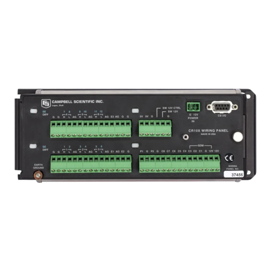
Page 15: Cr10X Wiring Panel
4X Set port x high 28 Wire Meas 5X Set port x low 29 INW Press 6X Toggle port x 7X Pulse port x 96 Port Subr. 97 Port Subr. 98 Port Subr. FIGURE OV1.1-2. CR10X Wiring Panel/Programming Instructions OV-3... - Page 16 12V DC power to the datalogger. may be used as an independent channel to The extra 12V and G terminals can be used to measure voltage with respect to the CR10X analog ground (AG). The single-ended connect other devices requiring unregulated channels are numbered sequentially starting 12V power.
-
Page 17: Ov1.2 Connecting Power To The Cr10X
64 locations. The the 9th window of the ∗B mode indicates that number of locations can be changed using the CR10X is currently in a low primary power the ∗A Mode. mode. (Section 1.6) 5. Final Storage - Final processed values are... - Page 18 Total 128 Kbytes Total 128 Kbytes The Operating System is loaded into Flash Memory at the factory. System Operating System Memory is used while the CR10X is System Memory running calculations, buffering data and (96 Kbytes) (4096 Bytes) for general operating tasks.
-
Page 19: Ov2.2 Program Tables, Execution Interval And Output Intervals
Subroutines, called from Tables 1 and 2, are INTERVAL AND OUTPUT INTERVALS entered in Subroutine Table 3. The size of The CR10X must be programmed before it will program memory can be fixed or automatically make any measurements. A program consists allocated by the CR10X (Section 1.5). -
Page 20: Ov2.3 Cr10X Instruction Types
Section 10) perform numerical operations than the time required to process the table, an on values located in Input Storage and execution interval overrun occurs; the CR10X store the results back in Input Storage. finishes processing the table and waits for the... -
Page 21: Input/Output Instructions
CR10X OVERVIEW INPUT/OUTPUT INSTRUCTIONS Specify the conversion of a sensor signal to a data value and store it in Input Storage. Programmable entries specify: (1) the measurement type (2) the number of channels to measure (3) the input voltage range... -
Page 22: Ov3. Communicating With Cr10X
In some cases, the exact action of a CR10X has powered up, the display is key depends on the mode the CR10X is in and meaningless until "∗" is pressed to enter a is described with the mode in the manual. -
Page 23: Index
Change the sign of a number or index an input location to loop counter with the SC32A is used to connect the serial I/O port of the CR10X to the 9 pin port of the Enter the decimal point SC32A labeled "Datalogger". Connect the Clear the rightmost digit keyed into "Terminal/Printer"... -
Page 24: Ov4.1 Programming Sequence
Each instruction has a number of measurements over some time interval and parameters that give the CR10X the information stores the processed results. A generalized it needs to execute the instruction. programming sequence is: The CR10X Prompt Sheet has the instruction 1. -
Page 25: Ov4.3 Entering A Program
CR10X OVERVIEW OV4.3 ENTERING A PROGRAM OV5. PROGRAMMING EXAMPLES Programs are entered into the CR10X in one of The following examples stress direct interaction three ways: with the CR10X using the CR10KD. At the beginning of each example is an EDLOG listing 1. -
Page 26: Ov5.1 Sample Program 1
CR10KD). 01:0.0000 Advance to execution In order to ensure that there is no active interval (In seconds) program in the CR10X, we will load an empty 01:5 Key in an execution program using the *D Mode: interval of 5 seconds. - Page 27 Input Storage. program, log data. No data are being saved. The next step is to have The CR10X is now programmed to measure the the CR10X send each internal temperature every 5 seconds and send reading to Final Storage.
-
Page 28: Ov5.2 Sample Program 2
TC output curve (Section 13.4). 5: Average (P71) Reps The internal temperature of the CR10X is not a Loc [ CR10XTemp ] suitable reference temperature for precision thermocouple measurements. It is used here 6: If time is (P92) for the purpose of training only. -
Page 29: Ov5.3 Editing An Existing Program
When editing an existing program in the offset of 0 outputs the reading in degrees C. A CR10X, entering a new instruction inserts the multiplier of 1.8 and an offset of 32 converts the instruction; entering a new parameter replaces reading to degrees F. - Page 30 03:10 Set Output Flag 0 The CR10X is programmed to measure the thermocouple temperature every sixty seconds. The If Time instruction sets the Output Flag at the beginning of every hour. Next, the Output Instructions for time and average are added.
-
Page 31: Ov6. Data Storage And Transfer Peripherals
CR10X OVERVIEW 09: P74 Minimize instruction 01:1 One repetition 02:10 Output the time of the daily minimum in hours and minutes 03:2 Data source is Input Storage Location 2. The program to make the measurements and to send the desired data to Final Storage has been entered. -
Page 32: Ov6.1 On-Site Options
The interface converts the CMOS logic levels of between the storage module and PC. Consult our dataloggers to RS-232 logic levels required Campbell Scientific if data playback to a non- by most computers. The CR23X has an on- IBM-compatible computer is required. -
Page 33: Ov6.2 Telecommunications Options
CR10X OVERVIEW laptop, but does not provide isolation. The permits dashboard mounting in a variety of SC929 draws approximately 100 mA from the vehicles without obstructing the view of the datalogger while connected. driver. DSP4 Heads-up Display - (Primarily intended Printer - Battery or ac-powered serial printers for vehicle test applications.) Displays any four... - Page 34 Analog Cellular - A cellular Motorola RF Base Station at the computer. Up to 254 transceiver and a Campbell Scientific field or stations can be interrogated over a single UHF voice modem are used to communicate or VHF frequency.
-
Page 35: Ov7. Specifications
BATTERIES: Any 12 V battery can be connected as a primary power source. Several power supply RESOLUTION: 0.67 mV Minimum AC Input Voltage: options are available from Campbell Scientific. (Sine wave mV RMS) Range (Hz) ACCURACY: ±5 mV; ±2.5 mV (0° to 40°C);... - Page 36 CR10X OVERVIEW This is a blank page. OV-24...
-
Page 37: Functional Modes
10 minutes, 8 measurements out of The sample rate for a CR10X measurement is 4800 (.17%) are missed: an acceptable statistical the rate at which the measurement instruction error for most populations. - Page 38 1.1.4 ∗ ∗ ∗ ∗ 4 PARAMETER ENTRY TABLE capability of being executed when a port goes The CR10X ∗4 mode is a table with up to one high (ports 6, 7, and 8 respectively). Any of these subroutines will interrupt Tables 1 and 2 hundred values.
- Page 39 Once the EDLOG created program has been been hand edited. sent to the CR10X, it can be saved in the Flash memory program storage area using the ∗D • Security is blocking access to ∗4.
-
Page 40: Displaying/Altering Input Memory, Flags, And Ports - ∗6 Mode
SECTION 1. FUNCTIONAL MODES entered and prior to saving a program listing in TABLE 1.2-1. Sequence of Time the ∗D Mode. The compile function is only Parameters in ∗ ∗ ∗ ∗ 5 Mode executed after a program change has been Display made and any subsequent use of any of these ID:DATA... -
Page 41: Compiling And Logging Data - ∗0 Mode
Mode. The same is true when the FLAGS programs are compiled with ∗B or ∗D. If D is keyed while the CR10X is displaying a location value, the current status of the user flags To minimize current drain, the CR10X should will be displayed in the following format: be left in the ∗0 Mode when logging data. - Page 42 SECTION 1. FUNCTIONAL MODES necessary for averages, standard deviations, Input Storage is used to store the results of histograms, etc. Intermediate Storage is not Input/Output and Processing Instructions. The values stored in input locations may be accessible by the user. displayed using the ∗6 Mode (Section 1.3).
-
Page 43: Cr10X Memory
Total 128 Kbytes Total 128 Kbytes The Operating System is loaded into Flash Memory at the factory. System Operating System Memory is used while the CR10X is System Memory running for calculations, buffering data (96 Kbytes) (4096 Bytes) and general operating tasks. - Page 44 Changing the size of program memory results in all data being erased. Enter 0 and the CR10X will assign the exact number needed. Entering 0 will also result in the CR10X erasing all data whenever the program is changed and compiled.
- Page 45 The signature for the same program will be different in a CR10X and a CR10X-2M. If the program has not been previously compiled, it will be compiled and run. 02: XXXXX...
-
Page 46: 1.7 ∗ ∗ ∗ ∗ C Mode -- Security
If security is enabled in PROGRAM the active program, it is enabled as soon as the The ∗D Mode is used to save or load CR10X program is run when the CR10X is powered up. programs, to set the degree to which memory is When security is disabled, ∗C will advance... -
Page 47: D Mode Commands
Each program saved takes up the memory when the CR10X is powered up. (If a Storage required for the program + 6 bytes. Module with a program 8 is connected when the... -
Page 48: Transferring A Program Using A Storage Module
When the flash program memory is full, all programs must If x=0 the CR10X is set for full duplex. be erased before any more can be added (error If x=1 the CR10X is set for half duplex. - Page 49 Table 1.8-10 shows the option codes available for setting the initial baud rate. Setting the initial Entry Display Comments baud rate forces the CR10X to try the selected baud rate first when connecting with a device. 13:00 Enter Command 13:00 Compile Option TABLE 1.8-9.
- Page 50 SECTION 1. FUNCTIONAL MODES This is a blank page. 1-14...
-
Page 51: Internal Data Storage
SECTION 2. INTERNAL DATA STORAGE Final Storage Area 1 is the default storage area 2.1 FINAL STORAGE AREAS, OUTPUT and the only one used if the operator does not ARRAYS, AND MEMORY POINTERS specifically allocate memory to Area 2. Final Storage is the memory where final processed data are stored. -
Page 52: Output Array Id
Final Storage IF THE STORAGE MODULE IS CONNECTED TO THE CR10X. If the Storage Module is not connected, the CR10X does not transmit the data nor does it advance the SPTR to the new DSP location. It saves the data until the Storage Module is FIGURE 2.1-2. -
Page 53: Data Output Format And Range Limits
Array, enter a location number that positions the above, the computations performed in the Display Pointer (DPTR) behind the desired data CR10X are done in floating point arithmetic. In and press the "A" key. If the location number Input and Intermediate Storage, the numbers... - Page 54 SECTION 2. INTERNAL DATA STORAGE is displayed by using the "#" key, the TABLE 2.3-1. ∗ ∗ ∗ ∗ 7 Mode Command Summary corresponding data point can be displayed by pressing the "C" key. Action Advance to next data point The same element in the next Output Array with the same ID can be displayed by hitting #A.
-
Page 55: Instruction Set Basics
Instructions are identified by a number. There are a fixed number of parameters associated with each instruction to give the CR10X the information required to execute the instruction. The set of instructions available in the CR10X is determined by the CR10X Operating System. -
Page 56: Voltage Range And Overrange Detection
Section 12, for more details. Voltages greater than 16 volts may permanently damage the CR10X. To index an input location (4 digit integer) or set port command (2 digit integer) parameter, C or NOTE: Voltages in excess of 5.5 volts... -
Page 57: Use Of Flags: Output And Program Control
Storage, and Flag 9 disables intermediate processing. Flags 1-8 may be used as desired Each group of Output Processing Instructions in programming the CR10X. Flags 0 and 9 are creating an Output Array is preceded by a automatically set low at the beginning of each Program Control Instruction that sets the Output execution of the program table. -
Page 58: Program Control Logical Constructions
SECTION 3. INSTRUCTION SET BASICS As an example, suppose it is desired to obtain a TABLE 3.8-1. Command Codes wind speed rose incorporating only wind speeds Go to end of program table greater than or equal to 4.5 m/s. The wind 1-9, 79-99 Call Subroutine 1-9, 79-99 speed rose is computed using the Histogram... -
Page 59: Instruction Memory And Execution Time
SECTION 3. INSTRUCTION SET BASICS location is less than the fixed value specified in Instruction 83, the command in that Instruction 83 is executed, and execution branches to the END Instruction 95 which closes the case test (see Instruction 93, Section 12). 3.8.2 NESTING A branching or loop instruction which occurs before a previous branch or loop has been... -
Page 60: Input/Output Instruction Memory And Execution Times
SECTION 3. INSTRUCTION SET BASICS TABLE 3.9-1. Input/Output Instruction Memory and Execution Times INPUT PROG. EXECUTION TIME (ms) INSTRUCTION LOC. BYTES MEASUREMENT RANGE Code 0 1-4 or NA Code 10 11-14 Code 20 21-24 Code 30 31-34 VOLT (SE) 3.0 + 40.2 * R 4.6 + 5.2R 2.0 + 2.8R 1.6 + 20.6 * R... -
Page 61: Processing Instruction Memory And Execution Times
SECTION 3. INSTRUCTION SET BASICS TABLE 3.9-2. Processing Instruction Memory and Execution Times R = No. of Reps. INPUT MEMORY PROG. INSTRUCTION LOC. INTER. LOC. BYTES EXECUTION TIME (ms) 1.0 + 0.2 ∗ exponent 30 Z=F 31 Z=X 32 Z=Z+1 33 Z=X+Y 34 Z=X+F 35 Z=X-Y... -
Page 62: Output Instruction Memory And Execution Times
SECTION 3. INSTRUCTION SET BASICS TABLE 3.9-3. Output Instruction Memory and Execution Times R = No. of Reps. INTER. MEM. FINAL PROG. EXECUTION TIME (ms) INSTRUCTION LOC. VALUES BYTES FLAG 0 LOW FLAG 0 HIGH 69 WIND VECTOR 2+9R (2, 3, or 4)R Options 00, 01, 02 4.0 + 17.4R 3.3 + 70.7R... -
Page 63: 3.10 Error Codes
9.6 volts and displays a double dash (--) if indicates that the fifth instruction in Table 1 caused the CR10X is currently in a low voltage shut error 23). Error 22, missing END, will indicate the down. Below approximately 8.5 volts the... - Page 64 SECTION 3. INSTRUCTION SET BASICS Compile IF and/or LOOP nested too deep Run Time SUBROUTINES nested too deep Compile Instruction 3 and interrupt subroutine use same port Compile Cannot use Control Port 6 as counter or interrupt subroutine with Instruction 15 or SDM or SDI-12 input/output instructions Editor...
-
Page 65: External Storage Peripherals
External data storage devices are used to provide a data transfer medium that the user can carry from the test site to the lab and to supplement the internal storage capacity of the CR10X, allowing longer periods between visits to the site. The standard data storage peripheral for the CR10X is the Storage Module (Section 4.4). -
Page 66: Mode Entries
CR10X will not advance the SPTR (Section 2.1) and the Storage Module If the CR10X is using the 9-pin connector for drops out of the queue until the next time other I/O tasks when Instruction 96 is executed, Instruction 96 is executed. -
Page 67: Telecommunications
(80, 81). Table 4.2-1 lists the keystrokes required to initiate a ∗8 data dump. requires that the user have access to the CR10X through a terminal or the CR10KD. The ∗8 Mode allows the user to retrieve a specific 4.3 PRINTER OUTPUT FORMATS... -
Page 68: 4.4 Storage Module
CR10X during on-line output, 2) different data to Example: be output to different Modules, and 3) transfer of 1,234,1145,23.65,-12.26,625.9 data from a Module that is left with the CR10X to a 1,234,1200,24.1,-10.98,650.3 Module that is hand carried to the site for data transfer (∗9 Mode). -
Page 69: Mode -- Sm192/716 Storage Module Commands
SC32A is needed. See Section 5 for with Instruction 96, the Storage Module(s) may interfacing details.) be either left with the CR10X for on-line data 2. Key in the appropriate commands as listed transfer and periodically exchanged, or brought in Table 4.2-1. - Page 70 SECTION 4. EXTERNAL STORAGE PERIPHERALS TABLE 4.5-1. ∗ ∗ ∗ ∗ 9 Commands for Storage Module COMMAND DISPLAY DESCRIPTION 01: 0000 RESET, enter 248 to erase all data and programs. While erasing, the SM checks memory. The number of good chips is then 01: XX displayed (6 for SM192, 22 SM716).
-
Page 71: Telecommunications Commands
Telecommunications is used to retrieve data from Final Storage directly to a computer/terminal and to program the CR10X. Any user communication with the CR10X that makes use of a computer or terminal is done through Telecommunications. - Page 72 2. All commands are of the form: [no.]letter, where the number may or may not be optional. The CR10X sends ASCII data with 8 bits, no parity, one start bit, and one stop bit. 3. Valid characters are the numbers 0-9, the...
- Page 73 [F.S. Area]A SELECT AREA/STATUS - If 1 or 2 does not precede the A to select the Final Storage Area, the CR10X will default to the Area last used (initially this is Area 1). All subsequent commands other than A will address the area selected.
- Page 74 Display/change value at Input Storage location. CR10X sends the value stored at the location. A new value and CR may then be sent. CR10X sends checksum. If no new value is sent (CR only), the location value will remain the same.
-
Page 75: Remote Programming Of The Cr10X
The PC208W Datalogger Support Software was the CR10X. PC208W’s Connect screen also developed by Campbell Scientific for use with offers such a Terminal window. The CR10X can IBM or compatible PC's. Datalogger programs be placed in the Remote Keyboard State by are developed on the computer using the sending either "7H"... - Page 76 OV3.2). an entry causes the entire entry to be sent, "control Q" is sent after each user entry). NOTE: Entering * 0 returns the CR10X to It is important to remember that the Remote the telecommunications command state. Keyboard State is still within Telecommunications.
-
Page 77: 6.1 Pin Description
SECTION 6. 9-PIN SERIAL INPUT/OUTPUT 6.1 PIN DESCRIPTION All external communication peripherals connect to the CR10X through the 9-pin subminiature D- type socket connector located on the front of the Wiring Panel (Figure 6.1-1). Table 6.1-1 shows the I/O pin configuration, and gives a brief description of the function of each pin. -
Page 78: Enabling And Addressing Peripherals
CR10X (Section 6.6). 6.3) to come from a modem if the device raises the CR10X's Ring line, and holds it high until the Up to 16 SDs may be addressed by the CR10X. CR10X raises the ME line. Only one modem/ Unlike an enabled peripheral, the CR10X terminal may be connected to the CR10X. -
Page 79: 6.3 Ring Interrupts
A modem which raises the Ring line will interrupt execution continues. As the 9-pin connector and gain control of the CR10X. A ring from a becomes available, each device in the queue will modem aborts data transfer to pin-enabled and get its turn until the queue is empty. -
Page 80: 6.5 Modem/Terminal Peripherals
CR10X sends a carriage return, line feed, "∗". the Ring, Clock Handshake (CLK/HS) and Synchronous Device Enable (SDE) lines to The ME line is held high until the CR10X receives establish communication. The CR10X can put an "E" to exit telecommunications. The ME is the SDs into one of six states. -
Page 81: Modem/Terminal And Computer Requirements
SDs must drop the Ring line in this state. This transmitted first and is always logic high. Each state is not used by SDs. The CR10X must bit transmitted is stable on the rising edge of force the SDs back to the reset state from State CLK/HS. -
Page 82: Sc32A Pin Description
SECTION 6. 9-PIN SERIAL INPUT/OUTPUT satisfy hardware handshake requirements of TABLE 6.7-1. SC32A Pin Description the computer/terminal. PIN = Pin number Table 6.7-2 lists the most common RS232 Signal Out of the SC32A to a peripheral configuration for Data Terminal Equipment. Signal Into the SC32A from peripheral 25-PIN FEMALE PORT: TABLE 6.7-2. - Page 83 0 to make the parity of the character from such a modem, especially when implemented correct. The CR10X ignores the 8th bit of a by computer software. character that is received, and transmits the 8th To overcome the limitations of half duplex, bit as a binary 0.
- Page 84 If you are using a computer to communicate with the datalogger, communication software If the CR10X is connected to the SC32A RS232 must be used to enable the serial port and to interface and a modem/terminal, and an "∗" is make the computer function as a terminal.
-
Page 85: Single-Ended Voltage/Switched 12 V Terminal - Cs500
SECTION 7. MEASUREMENT PROGRAMMING EXAMPLES This section gives some examples of Input Programming for common sensors used with the CR10X. These examples detail only the connections, Input, Program Control, and Processing Instructions necessary to perform measurements and store the data in engineering units in Input Storage. Output Processing Instructions are omitted (see Section 8 for some processing and program control examples). -
Page 86: Wiring Diagram For Cs500
±2500 mV 60 Hz Rejection 2: 25 INPUT LOCATIONS Range 1 Temp_C SE Channel 2 RH_pct Loc [ RH_pct Mult Offset ;Turn CS500 off. CR10X Temperature (Black) Relative Humidity (Brown) 12 V (Red) CS500 SWITCHED 12V Signal/Power Ground (Green) Shield (Clear) Jumper SWITCHED CONTROL FIGURE 7.1-1. -
Page 87: Differential Voltage Measurement
Ground at the LI-6262 is 0.065 V higher than ground associated current drain usually requires a at the CR10X. The LI-6262 can be programmed to power source external to the CR10X. A typical output a linear voltage (0 to 100 mV) that is connection scheme where AC power is not , 100 µmol/mol full... -
Page 88: Thermocouple Temperatures Using The Optional Cr10Tcr To Measure The Reference Temperature
When a number of thermocouple measurements channel 1 (1H), excitation channel 3 (E3) and are made at some distance from the CR10X, it is analog ground (AG). It is measured with often better to use a reference junction box located... -
Page 89: 7.5 107 Temperature Probe
Figure 7.4-1. Loc [ 107_T#1 ] If a more accurate reference temperature is Mult needed, use Campbell Scientific's AM25T Solid Offset State Thermocouple Multiplexer (Section 8.10). It uses a 1000 ohm PRT as the reference 7.6 207 TEMPERATURE AND RH... -
Page 90: Anemometer With Photochopper Output
Young Model 12102D Cup Anemometer, with a 10 (0.09792 m/s)/Hz x XHz + 0.2 m/s window chopper wheel. The photochopper PROGRAM circuitry is powered from the CR10X 12 V supply; AC power or back-up batteries should be used to Pulse (P3) compensate for the increased current drain. -
Page 91: Tipping Bucket Rain Gage With Long Leads
-10 to Closure. Counts from long intervals will be 40°C. The length of the cable from the CR10X used, as the final output desired is total rainfall to the PRT is 500 feet. -
Page 92: Wiring Diagram For Prt In 4 Wire Half Bridge
Reps The correct multiplier is found by connecting the ±25 mV 60 Hz Rejection PRT to the CR10X and entering Instruction 9 Ex Range with a multiplier of 1. The PRT is then placed in ±25 mV 60 Hz Rejection an ice bath (@ 0°C;... -
Page 93: Wire Half Bridge Used To Measure 100 Ohm Prt
SECTION 7. MEASUREMENT PROGRAMMING EXAMPLES FIGURE 7.10-1. 3 Wire Half Bridge Used to Measure 100 ohm PRT Two percent of 8.3 ohms is 0.17 ohms. 7.10 100 OHM PRT IN 3 WIRE HALF Assuming that the greater resistance is in wire BRIDGE B, the resistance measured for the PRT (R The temperature measurement requirements in... -
Page 94: Ohm Prt In 4 Wire Full Bridge
SECTION 7. MEASUREMENT PROGRAMMING EXAMPLES FIGURE 7.11-1. Full Bridge Schematic for 100 ohm PRT is obtained when the temperature range results 7.11 100 OHM PRT IN 4 WIRE FULL in an output voltage (V ) range which fills the BRIDGE measurement range selected in Instruction 6. -
Page 95: Wiring Diagram For Full Bridge Pressure Transducer
25 mV input range. The sensor is correction factor of 0.00385/0.00392 = 0.98214 calibrated by connecting it to the CR10X and using as the multiplier in Instruction 16 results in a Instruction 6, an excitation voltage of 2500 mV, a... -
Page 96: 7.13 Lysimeter - 6 Wire Full Bridge
CR10X due to voltage drop in the connecting cable is negligible. The average cable. The 6 wire full bridge (Instruction 9) avoids resistance of 22 AWG wire is 16.5 ohms per 1000... -
Page 97: Wire Full Bridge Connection For Load Cell
Assume that the cable between the convert mV/V into millimeters. (The result of load cell and the CR10X lays on the soil surface Instruction 9 is the ratio of the output voltage to the actual excitation voltage multiplied by 1000, and undergoes a 25°C diurnal temperature... -
Page 98: 7.14 227 Gypsum Soil Moisture Block
Section 8.3 gives an example using the AM416 the excitation voltage; this output is converted to Multiplexer to measure 16 Soil Moisture Blocks. gypsum block resistance with Instruction 59, Bridge Transform. FIGURE 7.14-1. 6 227 Gypsum Blocks Connected to the CR10X 7-14... -
Page 99: Nonlinear Thermistor In Half Bridge (Model 101 Probe)
-1.11341E-10 X Loc [ H2O_bar#1 ] 2.33651E-14 F(X) Loc [ H2O_bar#1 ] The CR10X will only allow 5 significant digits to the .15836 C0 right or left of the decimal point to be entered from the 6.1445 keyboard. The polynomial cannot be applied exactly -8.4189... -
Page 100: Water Level - Geokon'svibrating Wire Pressure Sensor
"plucking" and X Loc [ Temp_C#1 ] "pickup" coils and inducing the same frequency F(X) Loc [ Temp_C#1 ] on the lines to the CR10X. Instruction 28 then 4: -53.784 accurately measures how much time it takes to 5: 147.97 receive a user specified number of cycles. -
Page 101: Calibration Data For Sensor 3998
SECTION 7. MEASUREMENT PROGRAMMING EXAMPLES The following calculations are based on using a WELL MONITORING EXAMPLE Geokon model 4500 Vibrating Wire sensor. An In this example the vibrating wire sensor is used individual multiplier and offset must be to monitor water table height (Figure 7.16-2). calculated for each sensor used in a system. - Page 102 SECTION 7. MEASUREMENT PROGRAMMING EXAMPLES FIGURE 7.16-2. Well Monitoring Example 7-18...
-
Page 103: Hook Up To Avw1
SECTION 7. MEASUREMENT PROGRAMMING EXAMPLES FIGURE 7.16-3. Hook up to AVW1 Polynomial (P55) PROGRAM Reps X Loc [ Temp AVW1 & CR10X USED TO MEASURE 1 F(X) Loc [ Temp GEOKON VIBRATING WIRE SENSOR. 4: -104.78 5: 378.11 * Table 1 Program 6: -611.59... -
Page 104: Paroscientific "T" Series Pressure Transducer
3 mV 20 kHz (refer to Table 7.17-1). 12 mV 50 kHz 150 kHz Output period in microseconds Output frequency in kHz where x is range code AC voltage; must be centered around CR10X ground. 7-20... - Page 105 U + T CONNECTIONS Tau= measured period, in microseconds, of Figure 7.17-1 details the components required pressure for connecting the transducer to the CR10X. The user supplied components are commonly = measured period, in microseconds, of available at commercial electronic stores. temperature...
-
Page 106: Cr10X/Paroscientific "T" Series Transducer Wiring Diagram
SECTION 7. MEASUREMENT PROGRAMMING EXAMPLES FIGURE 7.17-1. CR10X/Paroscientific "T" Series Transducer Wiring Diagram PROGRAM EXAMPLE IF (X<=>F) (P89) X Loc [ Comp_Chk ] The following example reads the coefficients from a subroutine only when the datalogger program is compiled. The coefficients are Call Subroutine 1 stored in Input Locations 3 through 16. -
Page 107: To 20 Ma Sensor Using Curs100 Terminal Input Module
The dew point sensor is measured with a 21.801 differential voltage measurement on differential analog input 4. The CURS100 TIM and dew point sensor are wired to the CR10X wiring panel as shown in Figure 7.18-1. Loc [ D2 PROGRAM... -
Page 108: Wiring Diagram For Curs100 Terminal Input Module And 4 To 20 Ma Sensor
SECTION 7. MEASUREMENT PROGRAMMING EXAMPLES CR10X 100 Ω 4 to 20 mA ±0.01% Sensor CURS100 FIGURE 7.18-1 Wiring Diagram for CURS100 Terminal Input Module and 4 to 20 mA Sensor. 7-24... -
Page 109: Computation Of Running Average
SECTION 8. PROCESSING AND PROGRAM CONTROL EXAMPLES The following examples are intended to illustrate the use of Processing and Program Control Instructions, flags, dual Final Storage, and the capability to direct the results of Output Processing Instructions to Input Storage. The specific examples may not be as important as some of the techniques employed, for example: Directing Output Processing to Input Storage is used in the Running Average and Rainfall Intensity examples (8.1 and 8.2). -
Page 110: 8.2 Rainfall Intensity
SECTION 8. PROCESSING AND PROGRAM CONTROL EXAMPLES Sample (P70) Set Active Storage Area (P80) Reps Input Storage Area Loc [ 10smpl_av ] Array ID or Loc [ avg_i INPUT LOCATIONS Average (P71) Reps Loc [ XX_mg_M3 ] 1 Panl_Temp 15 Temp_i_5 2 10smpl_av 16 Temp_i_4 Spatial Average (P51) - Page 111 Array ID or Loc [ 15min_tot ] • Measure the 107 probe located at the AM416 for TC temperature reference. Totalize (P72) • CR10X sets the port high which resets the Reps AM416. Loc [ Precip_mm ] • A loop is entered; within each pass: •...
- Page 112 SECTION 8. PROCESSING AND PROGRAM CONTROL EXAMPLES FIGURE 8.3-1. AM416 Wiring Diagram For Thermocouple and Soil Moisture Block Measurements PROGRAM Loc [ TC_#1 Mult Offset Table 1 Program 600.0 Execution Interval (seconds) AC Half Bridge (P5) Reps Temp (107) (P11) ±250 mV Fast Range Reps SE Channel...
-
Page 113: Sub 1 Minute Output Interval Synched To Real Time
SECTION 8. PROCESSING AND PROGRAM CONTROL EXAMPLES If time is (P92) INPUT LOCATIONS Minutes (Seconds --) into a 1 Ref_Temp 12 TC_#11 23 Soil_#6 2: 30 Interval (same units as above) 2 TC_#1 13 TC_#12 24 Soil_#7 3: 10 Set Output Flag High 3 TC_#2 14 TC_#13 25 Soil_#8... -
Page 114: Sdm-Ao4 Analog Output Multiplexer To Strip Chart
Volts (SE) (P1) on weather data. The SDM-A04 may be used Reps with the CR10X to provide analog outputs to ±7.5 mV Slow Range strip charts. The output values in this example SE Channel... -
Page 115: Converting 0-360 Wind Direction Output To 0-540 For Strip Chart
0-360 Reps degree input to 0-540. (If you have a 0-540 pot, Address it can be used with the CR10X since the Wind Loc [ WS_out Vector Instruction, 69, will work with this output.) If time is (P92) -
Page 116: Use Of 2 Final Storage Areas - Saving Data Prior To Event
SECTION 8. PROCESSING AND PROGRAM CONTROL EXAMPLES Z=X (P31) Area 2. Thus, Area 2 holds 21 seconds (4 X Loc [ 0_360_WD ] values/second x 21 seconds = 84 locations). 2: 10 Z Loc [ 0_540_WD ] When 25 pounds is exceeded, 10 is loaded into IF (X<=>F) (P89) an input location and flag 1 is set high. -
Page 117: Logarithmic Sampling Using Loops
SECTION 8. PROCESSING AND PROGRAM CONTROL EXAMPLES If Flag/Port (P91) 8.9 LOGARITHMIC SAMPLING USING Do if Flag 1 is Low LOOPS Then Do A ground water pump test requires that water Do (P86) level be measured and recorded according to Set Flag 1 High the following schedule. - Page 118 SECTION 8. PROCESSING AND PROGRAM CONTROL EXAMPLES Beginning of Loop (P87) PROGRAM Delay Table 1 Program Loop Count Execution Interval (seconds) Do (P86) ;User must toggle Flag 1 to start measurements. Call Subroutine 1 If Flag/Port (P91) End (P95) Do if Flag 1 is Low Go to end of Program Table ;Loop 6, Output every 10 minutes until stopped by user.
-
Page 119: Covariance Correlation Programming Example
The vertical wind prop calibration differs the Input Storage locations for the processed results. from the U and V prop calibration. The fastest TABLE 8.10-1. Example Sensor Description and CR10X Multiplier and Offset DESCRIPTION SYMBOL SENSOR... -
Page 120: Example Input Channel And Location Assignments
SECTION 8. PROCESSING AND PROGRAM CONTROL EXAMPLES Table 8.10-3 lists the input channel bulb measurements to vapor pressure using configuration and Input Storage allocation for Instruction 57 requires atmospheric pressure. the measured values. After reading the new We'll use the standard atmosphere for the site input samples, the Level 2 measurements are elevation and key the value into Location 17 using the C command in the ∗6 Mode. - Page 121 SECTION 8. PROCESSING AND PROGRAM CONTROL EXAMPLES Thermocouple Temp (DIFF) (P14) PROGRAM Reps Table 1 Program ±2.5 mV Fast Range Execution Interval (seconds) DIFF Channel Type E (Chromel-Constantan) Ref Temp Loc Set Port(s) (P20) [ Ref_Temp ] 1: 9999 C8..C5 = nc/nc/nc/nc Loc [ Ta2 2: 9933 C4..C1 = nc/nc/1ms/1ms...
-
Page 122: Thirty Minute Output From Example
SECTION 8. PROCESSING AND PROGRAM CONTROL EXAMPLES Covariance/Correlation (P62) Real Time (P77) No. of Input Locations 1: 0110 Day,Hour/Minute No. of Means No. of Variances Sample (P70) No. of Std. Dev. Reps No. of Covariance Loc [ mean_W1 ] No. of Correlations Samples per Average First Sample Loc [ W1 Loc [ MEAN_W1 ]... -
Page 123: Fast Fourier Transform Examples
8.11.1. EXAMPLE WITHOUT BIN AVERAGING signal at the beginning of the first interval and the end of the last interval can be determined by The CR10X was used to generate data looking at the CR10X program that generated representing two superimposed sine wave signals, one at 1.25 Hz (amplitude = 1) and the other at... -
Page 124: Fft Real And Imaginary Results 0.25 And 1.25 Hz Signal
SECTION 8. PROCESSING AND PROGRAM CONTROL EXAMPLES FIGURE 8.11-2. FFT Power Spectra Analysis of 0.25 and 1.25 Hz Signal TABLE 8.11-1. FFT Real and Imaginary Results 0.25 and 1.25 Hz Signal BIN # FFT Ri FFT Ii 0.02303 0.009766 0.01036 0.019532 -0.00206 0.029298... -
Page 125: Fft Magnitude And Phase Results 0.25 And 1.25 Hz Signal
SECTION 8. PROCESSING AND PROGRAM CONTROL EXAMPLES TABLE 8.11-2. FFT Magnitude and Phase Results 0.25 and 1.25 Hz Signal BIN # FFT Mi FFT Pi 0.02303 0.009766 0.01036 0.019532 0.00206 0.029298 -99999 0.214852 0.00086 185.58 0.224618 0.01154 17.952 0.234384 0.20321 197.78 0.24415 0.62935... - Page 126 Intermediate Locations 1028 Y Loc [ _________ ] Z Loc [ #1 8.11.2 EXAMPLE WITH BIN AVERAGING The CR10X was used to generate data Z=X+F (P34) simulating wave data from an ocean buoy with 1025 X Loc [ _________ ] four superimposed sine wave signals, 0.1,...
-
Page 127: Simulated Ocean Buoy Wave Data
SECTION 8. PROCESSING AND PROGRAM CONTROL EXAMPLES FIGURE 8.11-3. Simulated Ocean Buoy Wave Data FIGURE 8.11-4. Simulated Ocean Buoy FFT Results 8-19... -
Page 128: Fft Bin Averaging Results From Simulated Ocean Buoy Wave Data
SECTION 8. PROCESSING AND PROGRAM CONTROL EXAMPLES TABLE 8.11-4. FFT Bin Averaging Results from Simulated Ocean Buoy Wave Data BIN # FREQUENCY FFT*0.1 BIN # FREQUENCY FFT*0.1 0.00195 0.0507 0.0039 0.05265 0.00585 0.0546 0.0078 0.05655 0.00975 0.0585 0.0117 0.06045 0.01365 0.0624 0.0156 0.06435... - Page 129 SECTION 8. PROCESSING AND PROGRAM CONTROL EXAMPLES If Flag/Port (P91) Z=FRAC(X) (P44) Do if Flag 2 is High X Loc [ #1 Then Do Z Loc [ #1 FFT (P60) Z=X+F (P34) Log (base 2) of Samples X Loc [ #1 Power Spectra/Taper Log (base 2) of Bins Z Loc [ _________ ]...
-
Page 130: Using The Switched 12 V To Power Sensors
X Loc [ _________ ] Y Loc [ _________ ] The Switched 12 V terminal on the CR10X Z Loc [ _________ ] wiring panel is used to power the ASPTCs. The maximum amount of current that the Switched End (P95) 12 V terminal can source is 600 mA. - Page 131 JUMPER WIRE BLACK SWITCHED 12 V BLACK FIGURE 8.12-1. Connections to Power Two 12 V ASPTCs with the Switched 12 V on the CR10X Wiring Panel PROGRAM Table 1 Program Thermocouple Temp (DIFF) (P14) Execution Interval (seconds) Reps ±2.5 mV Slow Range...
- Page 132 SECTION 8. PROCESSING AND PROGRAM CONTROL EXAMPLES Average (P71) Reps Loc [ Ref_Temp ] End (P95) End (P95) Input Locations 1 Ref_Temp 2 Lower_TC 3 Upper_TC 4 del_TC 8-24...
-
Page 133: Input/Output Instructions
-99999 in high resolution or -6999 in low resolution. *** 1 SINGLE-ENDED VOLTS *** inputs must be within ±2.5 V of the CR10X's ground (see Common Mode Range in Section 14.7.2). Pyranometer and thermopile sensors... - Page 134 Low Level AC (Pulse Channels Only) Input Hysteresis: 15 mV Excessive pulse voltage inputs can damage the Maximum Input Voltage: 20 V peak-to- CR10X. Refer to Figure 9-1 if reducing input peak voltage is required. Input Voltage and Frequency Range (64 Hz reset required above 2 kHz) •...
- Page 135 NOTE: If Control Ports 6, 7, or 8 are used the table is executed. for pulse measurements or interrupt subroutines, the CR10X will not go into the quiescent power state (1.3 mA) but will If a table execution was skipped because the...
-
Page 136: Pulse Count Configuration Codes
SECTION 9. INPUT/OUTPUT INSTRUCTIONS Excitation channel TABLE 9-2. Pulse Count Configuration Codes number Code Configuration Delay in hundredths of High frequency pulse (Index (--) to a second change from 8 Hz to 64 Hz reset) Excitation voltage Low level AC (Index (--) to (millivolts) change from 8 Hz to 64 Hz reset) Input location number... - Page 137 SECTION 9. INPUT/OUTPUT INSTRUCTIONS *** 6 FULL BRIDGE WITH SINGLE *** PARAM. DATA NUMBER TYPE DESCRIPTION DIFFERENTIAL MEASUREMENT Repetitions FUNCTION Range code for both This Instruction is used to apply an excitation measurements (Table voltage to a full bridge and make a differential 9-1) voltage measurement of the bridge output.
-
Page 138: Excitation/Integration Codes
This instruction reads the battery voltage and COMPENSATION writes it to an input location. The units for battery voltage are volts. At approximately 9.6 FUNCTION V the CR10X suspends measurements. This instruction is used to apply an excitation voltage and make two differential voltage PARAM. DATA measurements. - Page 139 Input location for first compensating FUNCTION temperature This instruction applies a 1.5 VAC excitation measurement (°C) across Campbell Scientific's Model 207 Input location number Temperature and RH Probe, makes a fast for first measurement single-ended measurement across a series Multiplier...
-
Page 140: Thermocouple Type Codes
Table 9-4 gives the Input locations altered: 1 per repetition thermocouple type codes for Parameter 4. Enter a 9 in front of the code and the CR10X will make an additional check on common mode range; -99999 is output for temperature if... - Page 141 TC FUNCTION (when indexed (--), This instruction measures the temperature (°C) becomes an input of a thermistor on the CR10X analog board. location containing This temperature is generally not adequate for voltage measurement) use as the thermocouple reference temperature TC type code (Table (Section 13.4).
-
Page 142: Port Configuration Option Codes
(C1-C8). On power-up, ports Input locations altered: 0 default to input configuration (i.e., they are not driven high or low by the CR10X, and can be *** 21 PULSE PORT WITH DURATION *** used to read the status of an external signal using Instruction 25). - Page 143 (low < 1.5V, 3.5 V < HIGH < 5 V) is used, (millivolts) it must be input to Digital Control Port #1. Option 2 is useful when 2 or more CR10X's are Input location number, required to start "Bursting" at the same time.
- Page 144 1000 (e.g., 0.001 represents 1 measurement). specified transition to trigger. For example, If 0 is entered for Parameter 6, the CR10X will when triggering on the rising edge, if the input continue to send data until the Instruction is...
- Page 145 If the Burst instruction specifies that Burst data second measurement for each channel, etc.). be sent to the serial port (i.e., Storage Module), CR10X program execution will pause until the Telecommunication mode is exited. During this NOTE: When the raw serial data option is pause telecommunications (i.e., view input...
- Page 146 NOTE: Voltages in excess of 5.5 volts Input locations altered: number of scans plus applied to a control port can cause the number of samples saved before trigger CR10X to malfunction. *** 24 CALIBRATION *** PARAM. DATA NUM.
-
Page 147: Period Average Output Options/Range Codes
SECTION 9. INPUT/OUTPUT INSTRUCTIONS the elapsed time between specific input conditions. *** 27 PERIOD AVERAGE (SE) *** There is only one timer and it is common to all tables (e.g., if the timer is reset in Table 1 and later FUNCTION in Table 2, a subsequent instruction in Table 1 to Instruction 27 measures the period... -
Page 148: Recommended Input Conditioning Circuit For Period Averaging
SECTION 9. INPUT/OUTPUT INSTRUCTIONS 1µF To single - ended input Sensor with Silicon diodes such as 1N4001 offset Figure 9-2. Recommended input conditioning circuit for period averaging. An internal gain stage is used to amplify low- frequencies (R1/(R1 + Xc)) that attenuates the level ac signals prior to a zero-crossing detector applied input signal. - Page 149 SECTION 9. INPUT/OUTPUT INSTRUCTIONS Single-ended input *** 29 INW PS9105 *** channel # Cycles to measure FUNCTION Time out (0.01 sec, at The Instrumentation Northwest PS9105 least the maximum Enhanced (5 psig model) Pressure Transducer duration of the number is used to measure water level. This instruction of cycles specified + 1 excites the PS9105 with a single excitation 1/2 cycles.)
- Page 150 **Function; channels allowing multiple SW8A's to be connected to 4,3,2,1 one datalogger. 16 addresses are available, ***Averaging option but for most applications Campbell Scientific Input location number recommends no more than 4 SW8A's be Mult connected to one datalogger. Offset Execution Time: 2.3 ms + 1.65 ms/value +...
- Page 151 SECTION 9. INPUT/OUTPUT INSTRUCTIONS Function Option 0 provides the state of the Starting input location signal at the time P102 is executed. A 1 or 0 number corresponds to high or low states, respectively. Mult Offset Function Option 1 provides signal duty cycle. Input locations altered: 1 per repetitions The result is the percentage of time the signal is high during the sample interval.
- Page 152 M command. The following specification has been implemented in the Standard SDI-12 commands are supported by CR10X. Features added in this version are the CR10X: marked with a dagger (†) and may not be supported by older SDI-12 sensors.
- Page 153 If Instruction Storage regardless of the Output Flag's state. The ∗7 mode of the CR10X cannot be used to 105 is placed in Table 1, program execution will be suspended during this delay. If it is placed in view text data.
- Page 154 C8. *** 106 SDI-12 SENSOR *** PARAMETER 4. INPUT LOCATION Instruction 106 allows a CR10X to be used as Input location where the returned data is stored. an SDI-12 sensor. The CR10X can make If multiple values are returned from the SDI-12...
- Page 155 PARAMETER 1. ADDRESS recorder (1-9).If the 'M' command is sent by the recorder x = 0. Enter the address for the CR10X acting as an SDI-12 sensor (0-9, †10-126 decimal value for Results of Instruction 106 ASCII character, see Appendix E). Each SDI-...
- Page 156 TYPE DESCRIPTION sensor CR10X. The first and second values are SDM Address (Base 4: from the ∗B mode of the sensor CR10X, giving 00..33) the number of watchdog errors (E08) and the SDMX50 channel number of table overruns that have occurred.
- Page 157 Bit period, 10µs units Read Lithium Battery Voltage Level (Indexing does nothing) Normally this parameter represents the bit Read Flash (for CR10X-1M or CR10X- period. If the parameter is indexed (--), the 2M) Errors value entered is an Input Location that contains the bit period to use.
- Page 158 SECTION 9. INPUT/OUTPUT INSTRUCTIONS PARAM DATA NUMBER TYPE DESCRIPTION Repetitions (Index (- - ) to skip repeat of excitation) Single-ended channel for first measurement Excitation channel number Starting Frequency (HZ) Ending Frequency (HZ) T (sweep, Units = 1 msec) N (Number of steps) Delay after excitation before measurement (Units = 1 msec)
- Page 159 SECTION 10. PROCESSING INSTRUCTIONS To facilitate cross referencing, parameter PARAM. DATA descriptions are keyed [ ] to the values given on NUMBER TYPE DESCRIPTION the PROMPT SHEET. These values are Destination input defined as follows: location [Z] = Destination input location for result Input locations altered: [X] = Input location of X [Y] = Input location of Y...
- Page 160 Dest. input for EXP(X) FUNCTION Divide X by Y and place the result in an input location. Division by 0 will cause the result to be Input locations altered: set to the maximum CR10X number (99999). *** 42 1/X *** PARAM. DATA NUMBER...
- Page 161 SECTION 10. PROCESSING INSTRUCTIONS PARAM. DATA *** 43 ABS(X) *** NUMBER TYPE DESCRIPTION FUNCTION Input location of X Take the absolute (ABS) value of X and place Fixed divisor the result in an input location. Dest. input loc. For X PARAM.
- Page 162 SECTION 10. PROCESSING INSTRUCTIONS Parameter 3 cannot be entered as an indexed PARAM. DATA location within a loop (Instruction 87). To use NUMBER TYPE DESCRIPTION Instruction 49 within a loop, enter Parameter 3 Swath [SWATH] as a fixed location and follow 49 with the Instruction 31 (Move Data).
- Page 163 *** 55 5TH ORDER POLYNOMIAL *** where X is the SVPW derived by Instruction 56. FUNCTION This relationship was derived by Campbell Evaluate a 5th order polynomial of the form Scientific from the equations for the SVPW and the SVPI given in Lowe's paper.
- Page 164 R which is equivalent to bulb temp. [X/(1-X)], where X is the value derived by the [WB TEMP.] standard CR10X Bridge Measurement Instructions (with appropriate multiplier and Destination input offset, Section 13.5) and R represents the location for vapor MULTIPLIER value.
- Page 165 SECTION 10. PROCESSING INSTRUCTIONS *** 60 FAST FOURIER TRANSFORM *** FFT Option X0 = No Taper 0X = Power Spectra THEORY X1 = Taper Instruction 60 performs a Fast Fourier 1X = Real & Imaginary Transform (FFT) on a set of data contained in 2X = Magnitude &...
- Page 166 January 1978. When the taper is used, the real/imaginary components, the CR10X applies a correction by multiplying the magnitude/phase components, or the power results by the ratio of the variance before the spectra.
- Page 167 To calculate the magnitude and phase the CR10X's FFT algorithm must first compute the FFT RESULTS WITH BIN AVERAGING real and imaginary components. Conversion...
-
Page 168: Example Of Fft Power Spectra Bin Averaging
SECTION 10. PROCESSING INSTRUCTIONS BIN FREQUENCY POWER SPECTRA The band width or the frequency covered by The result of the FFT with A bins averaged, are each averaged bin is equal to FA/N where F is (N/2A)-1 bins of average spectral energy (APSn) the sample frequency in Hz (1/scan interval in representing frequencies from 0 Hz to 1/2 the seconds) and A is the number of bins being... - Page 169 Number of correlations The instruction does not conform to the CR10X's desired four instruction types. Data located in Input Number of input Storage is processed, and the results returned to...
-
Page 170: Maximum Number Of Outputs And Output Order For K Input Values
SECTION 10. PROCESSING INSTRUCTIONS TABLE 10-2. Maximum Number of Outputs and Output Order for K Input Values. (The output order flows from left to right and from top to bottom) INPUTS: ..MAX NO. OUTPUTS TYPE OUTPUTS (1st) (2nd) (3rd) (4th) (Kth) Means... - Page 171 Final Storage. All but the last averaging 1. The square root algorithm in the period in the Output Interval will contain the CR10X returns a result of 0 for same number of input scans as specified by negative arguments.
- Page 172 /Tau ) * (1 - (D * (1 - T /Tau C * (1 - T In many situations, the CR10X must perform Temperature (°C) = measurement and processing tasks in addition U + Y to those associated with the COV/CORR...
- Page 173 0.2°C over the same temperature range. input storage locations. The ninth is the input location for the first data value; subsequent data Coefficients are entered using CR10X Instruction 30 values are placed in sequential input locations. (Z=F) or Instruction 65 (Bulk Load). A calibration sheet from Paroscientific lists the 14 coefficients.
-
Page 174: Quadrant That The Angle Falls In Is Defined By The Sign Of X And Y
SECTION 10. PROCESSING INSTRUCTIONS PARAM. DATA *** 66 ARCTAN *** NUMBER TYPE DESCRIPTION FUNCTION Input location of X Calculate the angle in degrees whose tangent is Input location of Y X/Y. The polarity of X and Y must be known to Destination input determine the quadrant of the angle, as shown location for... - Page 175 SECTION 11. OUTPUT PROCESSING INSTRUCTIONS Standard deviation of horizontal wind *** 69 WIND VECTOR *** fluctuations from sub-intervals is calculated as follows: FUNCTION Instruction 69 processes the primary variables σ(Θ)=[((σΘ ...+( σΘ of wind speed and direction from either polar +(σΘ...
-
Page 176: Input Sample Vectors
Standard deviation of wind direction, σ(Θu). where in the case of orthogonal sensors: This standard deviation is calculated using =(Ue +Un i Campbell Scientific's wind speed weighted Unit vector mean wind direction, Θ1: algorithm. Θ1=Arctan (Ux/Uy) Use of the Resultant mean horizontal wind... -
Page 177: Mean Wind Vector
) ( ( / )) Standard deviation of wind direction, σ σ σ σ (Θ Θ Θ Θ u), using Campbell Scientific algorithm: have never been greater than a few degrees. σ(Θu)=81(1- The final form is arrived at by converting from radians to degrees (57.296 degrees/radian). - Page 178 SECTION 11. OUTPUT PROCESSING INSTRUCTIONS *** 71 AVERAGE *** *** 74 MINIMIZE *** FUNCTION FUNCTION This instruction stores the average value over Operating in the same manner as Program 73, the given output interval for each input location this instruction is used for storing the MINIMUM specified.
- Page 179 SECTION 11. OUTPUT PROCESSING INSTRUCTIONS while the bin select value was within a particular PARAM. DATA sub-range, the value output to Final Storage NUMBER TYPE DESCRIPTION must be divided by the fraction of time that the Repetitions bin select value was within that particular sub- range (i.e., a standard histogram of the bin Number of bins select value must also be output).
- Page 180 SECTION 11. OUTPUT PROCESSING INSTRUCTIONS PARAM. DATA Code Result NUMBER TYPE DESCRIPTION xxx1 SECONDS (with resolution of 0.125 sec.) Repetitions (number of xx1x HOUR-MINUTE sequential locations to xx2x HOUR-MINUTE, 2400 instead of 0000 sample) x1xx JULIAN DAY x2xx JULIAN DAY, previous day during first Starting input location no.
- Page 181 SECTION 11. OUTPUT PROCESSING INSTRUCTIONS The output is a two dimensional Rainflow The histogram can have either open or closed Histogram for each sensor or repetition. One form. In the open form, a cycle that has an dimension is the amplitude of the closed loop amplitude larger than the maximum bin is cycle (i.e., the distance between peak and counted in the maximum bin;...
- Page 182 SECTION 11. OUTPUT PROCESSING INSTRUCTIONS Execution time: 6.5 - 7.0 ms, with 60 Amplitude Bins and one Mean Bin. Intermediate Storage locations required: Reps x (Bins+2 x [No. of Amplitude Bins] + 4), where Bins = No. Mean Bins x No. Amplitude Bins. Outputs Generated: No.
-
Page 183: Flag Description
SECTION 12. PROGRAM CONTROL INSTRUCTIONS *** 85 LABEL SUBROUTINE *** TABLE 12-1. Flag Description Flag 0 Output Flag FUNCTION Flag 1 to 8 User Flags This instruction marks the start of a subroutine. Flag 9 Intermediate Processing Subroutines are a series of instructions Disable Flag beginning with Instruction 85 and terminated with Instruction 95, END. - Page 184 (Instructions 105 and 106), and SDM When the loop is first entered, one pass through instructions (Instructions 100-102 or 107). the loop is made, then the CR10X delays until Error E33 will be displayed, at compile, if the next execution interval and makes the the above instructions are used together.
-
Page 185: Loop Example: Block Data Transform
Instruction location equal to 10. The Input that they are within. The maximum nesting Instructions to make the pressure and level in the CR10X is 11 deep. This applies to If temperature measurements are assumed. Then/Else comparisons and Loops or any combination thereof. -
Page 186: Example: Loop With Delay
SECTION 12. PROGRAM CONTROL INSTRUCTIONS The Loop with a delay may be used so that only those instructions within the Loop are executed End Table 1 while certain conditions are met. As a simple example, suppose it is desired to execute one Table 3 Subroutines set of instructions from midnight until 6 AM, Beginning of Subroutine... - Page 187 SECTION 12. PROGRAM CONTROL INSTRUCTIONS (Instruction 46) of the number of minutes since *** 90 STEP LOOP INDEX *** midnight by the specified real time interval. If the result is 0, the interval is up. Thus, the first interval FUNCTION of the day always starts at midnight (0 minutes).
- Page 188 FUNCTION assumes Final Storage Area 1. When Command 30 (Then/Else) is used with an If the CR10X is already communicating on the If Instruction, the Else Instruction is used to 9-pin connector when Instruction 96 is mark the start of the instructions to execute if executed, the output request is put in a queue the test condition is false (Figure 3.8-1).
- Page 189 TELECOMMUNICATIONS statement or subroutine. Instruction 97 must be run at least twice for each call, once to initiate Instruction 97 is used to have the CR10X initiate the call and another time to completely reset telecommunications in response to certain and clean up memory values used to make the conditions.
- Page 190 Parameter 1: Parameter 4: The datalogger will call out using the modem The CR10X will repeat the call at a fast interval specified in Parameter 1. If the call is to go specified by Parameter 4 (in 1 sec. units).
-
Page 191: Option Code For Modem Type And Baud Rate
SECTION 12. PROGRAM CONTROL INSTRUCTIONS complete ID# is not received by the CR10X CAUTION: Instruction 97 with the voice within the time allotted in parameter 3, the option and the SDI-12 instructions may not datalogger hangs up and waits for the time for be in same table. - Page 192 See SAT HDR GOES manual for This instruction is used to transmit data from details. CR10X Final Storage via a GOES satellite to a central ground station. See the TGT1 manual for information on Instruction 120. *** 121 ARGOS ***...
-
Page 193: Cr10X Measurements
Integrating the signal removes noise that could measurements and increases the throughput create an error if the signal were instantaneously rate. The current drain on the CR10X batteries sampled and held for the A/D conversion. There is lower when the fast integration time is used. -
Page 194: Timing Of Single-Ended Measurement
CR10X ground, any difference in DIFFERENTIAL VOLTAGE ground potential between the sensor and the MEASUREMENTS CR10X will result in an error in the measurement. For example, if the measuring NOTE: The channel numbering on the old junction of a copper-constantan thermocouple,... -
Page 195: The Effect Of Sensor Lead Length On The Signal Settling Time
In most good ground connection exists through the AC applications this settling time is adequate, but wiring. If a CR10X is used to measure the the additional wire capacitance associated with output from a laboratory instrument (both... -
Page 196: Exponential Decay, Percent Of Maximum Error Vs. Time In Units Of Τ
(t/τ) are contained in The settling time constant, τ in seconds, and the the 450 µs CR10X input settling interval (t). capacitance relationships are given in The familiar exponential decay relationship is Equations 13.3-3 through 13.3-5,... -
Page 197: Typical Resistive Half Bridge
SECTION 13. CR10X MEASUREMENTS FIGURE 13.3-2. Typical Resistive Half Bridge FIGURE 13.3-3. Source Resistance Model for Half Bridge Connected to the CR10X DETERMINING SOURCE RESISTANCE The source resistance for several Campbell Scientific sensors are given in column 3 of The source resistance used to estimate the Table 13.3-5. -
Page 198: Properties Of Three Belden Lead Wires Used By Campbell Scientific
SECTION 13. CR10X MEASUREMENTS FIGURE 13.3-4. Wire Manufacturers Capacitance Specifications, C TABLE 13.3-2. Properties of Three Belden Lead Wires Used by Campbell Scientific Belden Wire # Conductors Insulation (ohms/1000ft.) (pfd/ft.) 8641 1 shld. pair polyethylene 8771 1 shld. 3 cond. -
Page 199: Settling Error, In Degrees, For 024A Wind Direction Sensor Vs. Lead Length
SECTION 13. CR10X MEASUREMENTS FIGURE 13.3-6. Resistive Half Bridge Connected to Single-Ended CR10X Input , the source resistance, is not constant TABLE 13.3-3. Settling Error, in Degrees, for because R varies from 0 to 10 kohms over the 024A Wind Direction Sensor vs. Lead Length 0 to 360 degree wind direction range. -
Page 200: Measured Peak Excitation Transients For 1000 Foot Lengths Of Three Belden Lead Wires Used By Campbell Scientific
2) V ~ 2.5 µV, allowable measurement error independent from the signal leads. 3) t = 450 µs, CR10X input settling time The size of the peak transient is linearly related to the excitation voltage and increases as the 4) R... -
Page 201: Summary Of Input Settling Data For Campbell Scientific Resistive Sensors
8771 1-222 0-90 Estimated time constants are for 1000 foot lead lengths and include 3.3nfd CR10X input capacitance. ** Measured peak transients for 1000 foot lead lengths at corresponding excitation, V TABLE 13.3-6. Maximum Lead Length vs. Error for Campbell Scientific Resistive Sensors... -
Page 202: Source Resistances And Signal Levels For Ysi #44032 Thermistor
Converting the error to °C gives approximately a 0.33=°C error at 0°C, 5. Use the CR10X to measure the input 0.53°C error at 20°C, and a 0.66°C error at settling error associated with a given 40°C. -
Page 203: Half Bridge Configuration For Ysi #44032 Thermistor Connected To Cr10X
SECTION 13. CR10X MEASUREMENTS FIGURE 13.3-7. Half Bridge Configuration for YSI #44032 Thermistor Connected to CR10X Showing: A) large source resistance, B) large source resistance at point P, and C) configuration optimized for input settling 13-11... -
Page 204: Measuring Input Settling Error With The Cr10X
SECTION 13. CR10X MEASUREMENTS FIGURE 13.3-8. Measuring Input Settling Error with the CR10X FIGURE 13.3-9. Incorrect Lead Wire Extension on Model 107 Temperature Sensor thermocouple voltage and adding the 13.4 THERMOCOUPLE corresponding temperature difference to the MEASUREMENTS reference temperature. A thermocouple consists of two wires, each of a... -
Page 205: Limits Of Error For Thermocouple Wire
-0°C to +50°C range published in NBS Monograph 125), the is the ±0.2°C thermistor interchangeability thermocouple voltage measurement, and the specification. When a CR10X is outside of this polynomial error (difference between NBS temperature range, the polynomial error becomes standard and CR10X polynomial much worse (Figure 13.4-1), and may necessitate... -
Page 206: Thermistor Polynomial Error
In VOLTAGE MEASUREMENT light of this, the fixed temperature limits of error The accuracy of a CR10X voltage (e.g., +1.0°C for type T as opposed to the slope measurement is specified as 0.2% (0.1% 0 to error of 0.75% of the temperature) in the table... - Page 207 Table environmental operating range, so there is no 13.4-2 gives error limits for the thermocouple problem when the CR10X is used as the linearization functions. reference junction. External reference junction boxes, however, must also be within these temperature ranges.
-
Page 208: Example Of Errors In Thermocouple Temperature
SECTION 13. CR10X MEASUREMENTS measurements are to be made at a distance from ERROR SUMMARY the CR10X. In most situations, it is preferable to The magnitude of the errors described in the make the box the reference junction, in which case... -
Page 209: Diagram Of Junction Box
For example, in Instruction 6, as wires. The CR10X can be used to measure the shown in Figure 13.5-2, excitation is switched temperature gradients within the junction box. - Page 210 SECTION 13. CR10X MEASUREMENTS FIGURE 13.5-1. Circuits Used with Instructions 4-9 13-18...
-
Page 211: Excitation And Measurement Sequence For 4 Wire Full Bridge
SECTION 13. CR10X MEASUREMENTS FIGURE 13.5-2. Excitation and Measurement Sequence for 4 Wire Full Bridge TABLE 13.5-1. Comparison of Bridge Measurement Instructions Instr. # Circuit Description Instr. # Circuit Description DC Half Bridge The delay parameter 3 Wire Compensates for lead... -
Page 212: Calculating Resistance Values From Bridge Measurement
SECTION 13. CR10X MEASUREMENTS Calculating the actual resistance of a sensor multiplier and stores the result in the original which is one of the legs of a resistive bridge location. Instruction 42 computes the reciprocal usually requires the use of one or two Processing of a value in an input location. -
Page 213: Ac Excitation And Measurement Sequence For Ac Half Bridge
207 relative humidity measurement because the soil and water provide an alternate Instruction 12) reverses excitation polarity to path for the excitation to return to CR10X provide ion depolarization and, in order to ground, and can be represented by the model minimize the time excitation is on, grounds the diagrammed in Figure 13.6-2. -
Page 214: Calibration Process
R is the resistance between the excited maintained over the -25 to +50°C operating electrode and CR10X earth ground. With R range of the CR10X. Calibration is executed the network, the measured signal is: under four conditions: 1. - Page 215 512 times that the program that the instruction is executed. For example, table is executed. If the measurements are consider a CR10X mounted under the dash of being averaged, the effect of the overrun is an automobile, where temperature could easily negligible.
- Page 216 SECTION 13. CR10X MEASUREMENTS This is a blank page. 13-24...
-
Page 217: Protection From The Environment
SECTION 14. INSTALLATION AND MAINTENANCE 14.1 PROTECTION FROM THE 14.2 POWER REQUIREMENTS ENVIRONMENT The CR10X operates at a nominal 12 VDC. Below 9.6 volts the CR10X does not operate The normal environmental variables of concern properly. are temperature and moisture. The standard CR10X is designed to operate reliably from -25°... -
Page 218: Typical Current Drain For Common Cr10X Peripherals
SECTION 14. INSTALLATION AND MAINTENANCE TABLE 14.2-1. Typical Current Drain for Common CR10X Peripherals Typical Current Drain (mA) Peripheral Equipment Quiescent Active AM16/32 Multiplexer <0.21 AM25T Multiplexer AM416 Multiplexer COM100 Cellular Phone <0.5 <170 (stand-by) <1800 (on-line) COM210 Phone Modem 0.12... -
Page 219: Bpalk Power Supply
Datalogger Instruction 10 can be used to volts and a nominal rating of 7.5 amp-hours at monitor battery voltage. Replace the alkaline cells before the CR10X battery voltage drops 20°C. The amp-hour rating decreases with below 9.6 V. temperature as shown in Table 14.3-1. -
Page 220: Typical Alkaline Battery Service And Temperature
An AC transformer or solar panel should be connected to the PS12 at all times. The charging source powers the CR10X while float charging the lead acid batteries. The internal lead acid battery powers the datalogger if the charging source is interrupted. -
Page 221: Solar Panels
5 volts is needed to power External power sources must be disconnected external modems besides the capabilities of the from the CR10X and charging circuit in order to PS12LA. The PS512M supplies 5 volts to pin 1 measure the actual lead acid battery voltage. -
Page 222: Direct Battery Connection To The Cr10X Wiring Panel
TO THE CR10X WIRING PANEL CONNECTIONS For some applications, size restrictions or other If a CR10X is to be powered from the 12 Volts operational considerations may preclude the use of a motor vehicle, a second 12 V supply is also of Campbell Scientific power supply options. -
Page 223: Wiring Panel Grounding Diagram And Excitation Control
SECTION 14. INSTALLATION AND MAINTENANCE directed away from the CR10X through the 14.7 GROUNDING diodes. The fuse may be replaced by soldering 14.7.1 PROTECTION FROM LIGHTNING another 30 AWG wire to the soldering pads provided. Primary lightning strikes are those where lightning hits the datalogger or sensors directly. -
Page 224: Wiring Panel
In the field, an earth ground may be created required to compensate for line losses between through a grounding rod. A 12 AWG or larger the CR10X and the excitation port on the Wiring wire should be run between a Wiring Panel Panel (see Figure 14.7-1). -
Page 225: Relay Driver Circuit With Relay
If the peripheral demands than shown in Figures 14.10-1 and 2. to be powered draws in excess of 75 mA at For more information contact Campbell room temperature (limit of the 2N2907A Scientific's Marketing Department. -
Page 226: Removing Wiring Panel
SECTION 14. INSTALLATION AND MAINTENANCE volts. If the lithium cell is removed or allowed to 14.11 MAINTENANCE discharge below the safe level, the CR10X will The CR10X Wiring Panel and power supplies still operate correctly while powered. Without require a minimum of routine maintenance. -
Page 227: Removing End Cap
Replace the desiccant taped to the circuit board holder with M EA w ar S /N a fresh packet before reassembling the CR10X. : X 10 , 19 , 19 FIGURE 14.11-3. Removing Circuit Board... - Page 228 SECTION 14. INSTALLATION AND MAINTENANCE This is a blank page. 14-12...
-
Page 229: A. Glossary
When not used as a 1 stop bit (total 9 bits) would be transmitted in clock line, the CLK/HS (pin 7) line in the CR10X 9/9600 sec. = .94 ms or about 1000 is primarily used to detect the presence or characters/sec. - Page 230 MODEM/TERMINAL: Any device which: 1) in the ID Field of the display. has the ability to raise the CR10X's ring line or be used with the SC32A to raise the ring line PRINT DEVICE: Any device capable of...
- Page 231 Final scaled to engineering units, and the reading Storage. Programming can be separated into 2 stored in Final Storage. The CR10X has the tables, each having its own user-entered ability to scan sensors at a rate exceeding the Execution Interval.
- Page 232 APPENDIX A. GLOSSARY This is a blank page.
-
Page 233: B.1 Specifications
CR10X control ports. CLEAR-TO-SEND (CTS) NOTE: If the received data is numeric The sensor signals the CR10X that it is ready to values, Instruction 15 converts a maximum receive the preamble or data (Section B3, of seven digits in a row. Leading zeros will Parameters 3 and 9). -
Page 234: Circuit To Limit Input To 0 To 5 Volts
= locations; data requiring a different configuration. Input termination character (0..255) Maximum number of input The CR10X sequentially increments sets of characters control ports and input locations with each repetition. The number of control ports used for Time out for CTS and/or each repetition (2, 3 or 4) depends on whether Input (.01 secs) - Page 235 PARAMETER 3 - CTS / DELAY BEFORE SEND "+1.23E-12" is converted into two numbers: If Parameter 3 is zero (0), the CR10X waits for 1.23 and -12.0. The "E" is interpreted as a data the Clear To Send to come high before sending point delimiter.
- Page 236 The termination character is used to mark the OS10X version 1.0014), the first digit specifies end of the ASCII string received by the CR10X. the TXD or RXD line and the second digit Regardless of the configuration code, all 8 bits...
-
Page 237: B.4 Control Port Configurations And Sensor Wiring
Instruction 15 is delayed for an extended period. CONFIGURATION 3 PARAMETER 10 - INPUT LOCATION Serial data are output from the CR10X with the This parameter defines the location in the aid of the CTS line. There is no input. -
Page 238: Input/Output Configurations
Serial data are output and serial data received of these instructions can be used if the search by the CR10X. The CTS line is used. string is longer than 8 characters. Separate Parameter 3 must be zero while Parameters 6 different types of filter strings with a null and 8 must be greater than zero. - Page 239 APPENDIX B. CONTROL PORT SERIAL I/O INSTRUCTION 15 typically have a defined serial output protocol numerical values the commas are treated as data called NMEA 0183. NMEA 0183 is an interface delimiters resulting in each navigation value protocol created by the National Marine residing in a unique input location.
-
Page 240: B.6 Program Examples
APPENDIX B. CONTROL PORT SERIAL I/O INSTRUCTION 15 The following program example will read-in the GGA and VTG GPS strings. Since this program is unique to the GPS application, additional data processing will be required to decode and format these strings. - Page 241 The purpose of this hook-up is to read the B.6.1.2 CR10X/BAROMETER HOOK-UP barometer on a standard RS-232 device, such as a printer or terminal instead of the CR10X. If Table 2 provides connection information for two failure occurs, this hook-up allows using a third TTL and one RS-232 version of data transfer.
-
Page 242: Cr10X/Barometer Connection Details
RTS/DTR connected to its shut down or DTR line Output start location (no output to transfer data. No CTS or output is required. It from CR10X) therefore uses 2 CR10X ports, as described by Number of locations to send "CONFIGURATION 1" (Section B4). (no output from CR10X) - Page 243 APPENDIX B. CONTROL PORT SERIAL I/O INSTRUCTION 15 Input termination character is used, Parameter 8 should be equal or one Carriage Return greater than the number of characters per Max characters to receive + 1 barometer output. 09: 100 Delay for input is 1.0 second First input location, User's choice Table 3 provides information on the number of Multiplier...
-
Page 244: Number Of Characters/Output And Memory Requirements For Various Barometer Output Modes
TABLE B-3. Number of Characters/Output and Memory Requirements for Various Barometer Output Modes Example: 100 samples are averaged by the average of one measurement. The following barometer connected to the CR10X via hook-up considerations are accounted for in the program. •... - Page 245 APPENDIX B. CONTROL PORT SERIAL I/O INSTRUCTION 15 If X<=>F START: Limit testing X Loc AIR, mb >= If reading is > 1300 mb 1300 Set high Flag 1 then set Flag 1 high If X<=>F X Loc AIR, mb <...
-
Page 246: Wiring Diagram For Cr10X To Cr10X Communication Example
RTS/DTR C6 ----------->C8 Interrupt; SBR 98 C7<----------- C6 RTS/DTR C8 ----------->C7 FIGURE B-2. Wiring Diagram for CR10X to CR10X Communication Example CR10X#1 PROGRAM - SEND DATA Table 1 Programs Sec. Execution Interval Beginning of Loop Start loop to generate values... -
Page 247: Appendix B. Control Port Serial I/O Instruction 15
2:VALUE #2 5:VALUE #5 8:VALUE #8 11:COUNTER 3:VALUE #3 6:VALUE #6 9:VALUE #9 12:_________ CR10X#2 PROGRAM - RECEIVE DATA Table 3 Subroutines Beginning of Subroutine Subroutine Number Control Port Serial I/O Repetitions Configuration code RS-232, 1200 bd CTS/Delay before send... -
Page 248: B.7 Summary Of Barometer Jumper Configurations
APPENDIX B. CONTROL PORT SERIAL I/O INSTRUCTION 15 B.7 SUMMARY OF BAROMETER JUMPER CONFIGURATIONS Jumper # 7 6 5 4 3 2 1 0 Barometer mode (serial output) u u r r n n 0 0 Barometer mode (parallel output) u u 0 b n n 0 1 Altimeter mode (serial output) u u r r n n 1 0... -
Page 249: C.1 Telecommunications Command With Binary Responses
A note on datalogger OS versions: a J command, it will remain set until reset by Beginning with Version 1.10 of the CR10X another J command or telecommunications is operating system (released October 1999), the terminated. - Page 250 APPENDIX C. BINARY TELECOMMUNICATIONS the most significant byte will still abort the flags byte, four bytes for each input location command. requested in the J command, Final Storage data in CSI's binary format if requested by the J command, and terminating in 7F 00 If “b”...
- Page 251 The optional ports byte (currently on return if For loop count = 1 to 24 do the following: requested by a CR10X J command) expresses the datalogger port status. The most significant If the MSB is one, then add Bit Value to the bit represents Port 8, and so on to the least Mantissa.
-
Page 252: C.2 Final Storage Format
Data byte 2 to 4 = D9 99 9A HEX (or 891290 decimal). CR10X data is formatted as either 2 byte LO Resolution or 4 byte HI Resolution values. The Data byte 1 is converted to binary to find the first two bytes of an Output Array contain a unique Sign. -
Page 253: C.3 Generation Of Signature
A,B = 0; C = 1 - Third byte of a 4 byte value. A = 0; remaining bits = 1 - First byte of a 2 byte "dummy" word. The CR10X always transmits a 0 for the 2nd byte, but the word can be decoded on the basis of the 1st byte only. - Page 254 2. Ignore any carry bit resulting Program listings are sent in ASCII. At the end from the add. of the listing, the CR10X sends control E (5 hex or decimal) twice. = shift left (S (n)) + carry Table 1.8-4 is an example of the program listing...
- Page 255 ^B can be sent to discard the current buffer and ^E ^E reset the signature. If the signature is correct, ^D ^D can be sent to tell the CR10X to load the LOAD PROGRAM FROM ASCII FILE buffer into the editor and reset the signature.
- Page 256 APPENDIX C. BINARY TELECOMMUNICATIONS This is a blank page.
-
Page 257: D. Cr10X 37 Pin Port Description
APPENDIX D. CR10X 37 PIN PORT DESCRIPTION PIN # DESCRIPTION PIN # DESCRIPTION EX CTRL 3 EX CTRL 2 EX CTRL 1... - Page 258 This is a blank page.
-
Page 259: E. Ascii Table
APPENDIX E. ASCII TABLE American Standard Code for Information Interchange Decimal Values and Characters (X3.4-1968) Dec. Char. Dec. Char. Dec. Char. Dec. Char. CONTROL @ SPACE CONTROL A CONTROL B " CONTROL C CONTROL D CONTROL E CONTROL F & CONTROL G CONTROL H CONTROL I... - Page 260 This is a blank page.
- Page 261 APPENDIX F. DYNAGAGE SAP-FLOW (P67) Four voltages must be stored sequentially F1. FUNCTION beginning with the Input Loc option stated in The Dynagage Processing Instruction, P67, is Parameter 1. used in conjunction with a Dynamax, Inc. Dynagage stem flow gage. Instruction 67 INPUT LOCATION calculates the sap flow rate within a plant stem Loc 1: Ch (Thermopile (mV))
- Page 262 APPENDIX F. DYNAGAGE SAP-FLOW (P67) and 8 are 0.5 °C and 0.042 cm s , respectively. F2.4 INSTRUCTION OUTPUT These values should be used unless conditions PARAMETER 9 determined by the user indicate otherwise. Two output options are available. PARAMETER 7 Option 0 Option 1 Low-flow filter (0.5°C).
- Page 263 APPENDIX F. DYNAGAGE SAP-FLOW (P67) If Par 7 µ 0.0 then go to XXXXXX Appendix A If Q f < (0.2*P in ) and If dT < Par 7, then Sapflow Instruction P67 Processing = 0.0 Loc = input location assuming input locations 1, If Q f <...
- Page 264 APPENDIX F. DYNAGAGE SAP-FLOW (P67) This is a blank page.
-
Page 265: G.1 Introduction
Datalogger initiated communications, commonly referred to as “callback," enables the datalogger to initiate a call back to a computer. A CR10X uses Instruction 97 to initiate a call. For complete information on Instruction 97 and its parameters, refer to section 12. -
Page 266: Com Port Hardware Settings
Setup the Connection to the site. Figure G.3-1 shows an example station for 12: IF (X<=>F) (P89) a CR10X site called “Logan”. Below is an X Loc [ AIR_TEMP ] example of the three devices required for the <... - Page 267 APPENDIX G. DATALOGGER INITIATED COMMUNICATIONS • Once the network’s connection settings are On the DataCollection screen, saved, manually attempt to call the station and “Data File Name” must be verified. collect data to make sure it is setup correctly. (Weather.DAT for this example, Figure G.3-4).
- Page 268 APPENDIX G. DATALOGGER INITIATED COMMUNICATIONS FIGURE G.3-2. COM Port Hardware Settings FIGURE G.3-3. Example Modem Settings...
- Page 269 APPENDIX G. DATALOGGER INITIATED COMMUNICATIONS FIGURE G.3-4. Example Data Collection Settings FIGURE G.3-5. Example Schedule Settings...
-
Page 270: G.4 Pc208 Dos Computer Software And Its Computer Setup
• Answer any incoming calls In this example, the file CALLME96.SCR is used. You may name the file anything you Telecommunication Parameters For Station: Datalogger Type: CR10X Security Code: Use Asynchronous Communications Adapter: COM2 Communications Baud Rate: 9600 Data File Format:... - Page 271 APPENDIX G. DATALOGGER INITIATED COMMUNICATIONS Telecommunications Program ver. 7.3 Copyright (C) 1986,1991 Campbell Scientific, Inc. Executing script file "C:\PC208\CALLME96" Waiting for: - next wake up time (01/19/38 03:14:07) - PC203 on/off switch to be turned on - modem ring signal to become active...
- Page 272 APPENDIX G. DATALOGGER INITIATED COMMUNICATIONS This is a blank page.
-
Page 273: Option Code For Modem Type And Baud Rate
Section H.3 covers programming requirements datalogger. This should not be confused with for the calling CR10X. Section H.4 shows the the flag that the calling datalogger sets in the programming requirements for the remote remote datalogger (specified in Instruction 63). - Page 274 '”539” every 2 the Failure Location. minutes. The CR10X toggles Flag 1 in the remote datalogger to trigger measuring and H.3.2 INSTRUCTION 63 data collection. It collects 3 input locations beginning at the remote datalogger’s location 1.
-
Page 275: H.4 Remote Datalogger Programming
2 minutes at using the RF When the flag is set high, measurements and Path of “4 10F” (that is from the calling CR10X processing are done; then the flag is set low. to RF ID# 4 to RF ID# 10 at the remote site). - Page 276 APPENDIX H. CALL ANOTHER DATALOGGER VIA PHONE OR RF Table 1 Programs Sec. Execution Interval If Flag 1 is set Then Do Battery Voltage Loc : Panel Temperature Loc : Temp 107 Probe IN Chan Excite all reps w/EXchan 1 Loc : Mult Offset...
-
Page 277: I.1 Terminology
Modbus communication capability is available as a Library Special on the CR10 and CR10X dataloggers. The implementation of MODBUS on the CR10 and CR10X allows input locations, ports, and flags to be read or to be set. Not supported are historical data retrieval, program downloads, setting the clock, and other functions of PC208. -
Page 278: I.3 More On Modbus
APPENDIX I. MODBUS ON THE CR10 AND CR10X I.2.1 RF COMMUNICATIONS Example 1: Function 1 to read coils 1 to 16 from slave device 17 The Campbell Scientific UHF/VHF radio package is of course compatible with PC208. To also do Modbus on SCADA packages using... - Page 279 APPENDIX I. MODBUS ON THE CR10 AND CR10X The register data is returned as two bytes per register and two registers per input location. Response for example 2: Slave address Function Byte Count Data Hi (Register 40009) Data Lo (Register 40009)
- Page 280 APPENDIX I. MODBUS ON THE CR10 AND CR10X This is a blank page.
- Page 281 APPENDIX J. TD OPERATING SYSTEM ADDENDUM FOR CR510, CR10X, AND CR23X MANUALS...
- Page 282 This is a blank page.
- Page 283 TD OPERATING SYSTEM ADDENDUM FOR CR510, CR10X, AND CR23X MANUALS REVISION: 1/03 COPYRIGHT 2002-2003 CAMPBELL SCIENTIFIC, INC.
- Page 284 This is a blank page.
- Page 285 TABLE DATA ADDENDUM TD and PakBus Operating System Addendum for CR510, CR10X, and CR23X Manuals AD1 Major Differences Table Data (TD) operating systems have two major differences from the standard operating systems: First - the namesake - in the way data are stored internally and second, in the options available for transferring that data to external devices.
- Page 286 TABLE DATA ADDENDUM AD2 Overview of Data Storage Tables Within a data table, data is organized in records and fields. Each row in a table represents a record and each column represents a field. To understand the concept of tables it may be helpful to consider an example. A CR10-TD is to be used to monitor 3 thermocouples (TC).
- Page 287 Edit the CSI file with a text editor (e.g., “Notepad” - Edlog will not allow you to make and save this change) and add –TD to the datalogger type on the first line, for example, change: ;{CR10X} ;{CR10X-TD}. Save the CSI file and close the editor.
- Page 288 Section 5 TD operating system is different than that of the standard operating systems. Campbell Scientific provides software for communications; a description of the protocol is beyond the scope of this addendum. Many of the peripherals discussed in section 6 are not supported by Section 6 the TD operating system.
- Page 289 TABLE DATA ADDENDDUM The TD operating system does not use the output Flag 0. Section 12 Commands dealing with it are not valid. Instruction 92 – There is no option for minutes, time is in seconds only. Instructions Not In TD OS: Instruction 96 –...
- Page 290 TABLE DATA ADDENDUM This is a blank page. AD-6...
- Page 291 Table OV3.2-1 in the CR10X Manual is incorrect for the TD operating system. See Table OV4.1-1 below. The following sections OV4, OV5, and OV6 replace those in the CR10X Manual.
- Page 292 2. Enter the Input/Output instructions required number. Each instruction has a number of to measure the sensors. parameters that give the CR10X the information it needs to execute the instruction. 3. If processing in addition to that provided by the Output Processing Instructions (step 5)
- Page 293 Enter the location # and advance to the second program instruction. The CR10X is now programmed to read the internal temperature every 5 seconds and place the reading in Input Storage Location 1. The program can be compiled and the temperature displayed.
- Page 294 Wait a few seconds: 01:21.423 The CR10X has read the sensor and stored the result again. The internal temp is now 21.423°C. The value is updated every 5 seconds when the table is executed. At this point the CR10X is measuring the temperature every 5 seconds and sending the value to Input Storage.
- Page 295 TC output curve (Section 13.4). In this example, the sensor is measured once a minute, and the average temperature is output The internal temperature of the CR10X is not a every hour. Once a day the maximum and suitable reference temperature for precision minimum temperatures and the times they occur thermocouple measurements.
- Page 296 03: 0 Automatically allocate # of records The CR10X is programmed to measure the thermocouple temperature every sixty seconds. The CR10X automatically allocates the number of records. Time information is automatically stored. Next the output instruction for the average is added.
- Page 297 OV6. DATA RETRIEVAL OPTIONS When editing an existing program in the Data is retrieved over some form of CR10X, entering a new instruction inserts the telecommunications link, whether it be RF instruction; entering a new parameter replaces (radio), telephone, short haul modem, coaxial the previous value.
- Page 298 2. THE DSP4 HEADS UP DISPLAY ALLOWS THE USER TO VIEW DATA IN INPUT STORAGE. ALSO BUFFERS FINAL STORAGE DATA AND WRITES IT TO CASSETTE TAPE, PRINTER OR STORAGE MODULE. 3. ALL CAMPBELL SCIENTIFIC RS-232 INTERFACES HAVE A FEMALE 25 PIN RS-232 CONNECTOR. FIGURE OV6.1-1. Data Retrieval Hardware Options...
- Page 299 SECTION 1. FUNCTIONAL MODES Sections 1.5 and 1.8 are replaced by the following sections. 1.5 MEMORY ALLOCATION - ∗A Intermediate Storage is a scratch pad for Output Processing Instructions. It is used to 1.5.1 INTERNAL MEMORY store the results of intermediate calculations necessary for averages, standard deviations, When powered up with the keyboard display histograms, etc.
- Page 300 How it works: Total 128 Kbytes The Operating System is loaded into Flash Memory at the factory. System Operating System Memory is used while the CR10X is 32K SRAM running for calculations, buffering data (96 Kbytes-CR10X) Main Memory and general operating tasks.
-
Page 301: Description Of ∗A Mode Data
2M. Please be patient while the reset takes locations allowed. Intermediate Storage and place; if the CR10X is turned off in the middle of Final Storage are erased when the number of a reset, it will perform the reset the next time it is Input locations is changed. - Page 302 Final Storage are reset). When "∗D" is keyed in, the CR10X will display "13:00". A command (Table 1.8-1) is entered 1.8.2 PROGRAM TRANSFER WITH STORAGE by keying the command number and "A".
-
Page 303: Baud Rate Codes
TABLE 1.8-11. PakBus Address and Routing Table Table 1.8-10 shows the option codes available for setting the initial baud rate. Setting the initial baud rate forces the CR10X to try the selected Entry Display Comments baud rate first when connecting with a device. - Page 304 TD ADDENDUM SECTION 1. FUNCTIONAL MODES The *D15 entries are sent when the program is 1.8.11 SET PAKBUS ROUTER BEACON retrieved. They can also be set like other *D INTERVAL settings via the DLD file. TABLE 1.8-13. Set Beacon interval 1.8.9 ALLOCATE MEMORY FOR GENERAL PURPOSE FILES Entry...
- Page 305 TD ADDENDUM SECTION 1. FUNCTIONAL MODES 1.9 *9 DATA TABLES SIZES. TABLE 1.8-14. Set PakBus Neighbors The *9 Mode is used to view the sizes of the Data Storage Tables (section 2.1) created by Entry Display Comments the datalogger program (*1, *2, or *3). The *9 Mode will also display how long until any 13:00 Enter Command...
- Page 306 TD ADDENDUM SECTION 1. FUNCTIONAL MODES This is a blank page. AD-1-8...
- Page 307 To understand the concept ANY CHANGES. of tables it may be helpful to consider an example. A CR10X is to be used to monitor 3 A time stamp and record number are thermocouples (TC). Each hour a temperature automatically included with the each record in for each of the three TC is to be stored.
- Page 308 TD ADDENDUM—SECTION 2. INTERNAL DATA STORAGE • Storage − Number of Final Storage Locations The output interval is not an even multiple of the scan rate (table execution interval). available for Data Storage Tables. Section 1.5.2 • Table execution is such that Instruction 84 Tables −...
- Page 309 2.2 DATA OUTPUT FORMAT AND 0.0086731924 is better than 0.000000001. RANGE LIMITS Data is stored internally in Campbell Scientific's A precise calculation of the resolution of a Binary Final Storage Format (Appendix C.2). number may be determined by representing the Data may be sent to Final Storage in either number as a mantissa between .5 and 1...
- Page 310 TD ADDENDUM—SECTION 2. INTERNAL DATA STORAGE records long is maintained inside Intermediate TABLE 2.3-1. *7 Mode Command Summary Storage to keep track of "holes" in the recorded data, due to watch dog errors or clock changes, ACTION so that the time of each record can be implicitly "Advances"...
-
Page 311: Instruction Set Basics
Compile Storage Area #2 not allocated Compile Instruction 3 and interrupt subroutine use same port Run Time CR10X reset by watchdog timer Compile Cannot use Control Port 6 as counter or interrupt Run Time Insufficient Input Storage subroutine with... - Page 312 TD ADDENDUM—SECTION 3. INSTRUCTION SET BASICS Program Program Storage Area Transfer full Program Program does not exist in Transfer Flash memory Program Addressed Transfer device not connected Program Data not received within Transfer 30 seconds Program Uncorrectable errors Transfer detected Program Wrong file type or editor Transfer...
- Page 313 THIS SECTION ENTIRELY REPLACES THE CR10X MANUAL SECTION 8. SECTION 8. PROCESSING AND PROGRAM CONTROL EXAMPLES This section contains examples for the CR10X. The appropriate voltage range codes would have to be selected for the CR23X (see CR23X Manual Section 8 for the measurement instructions). The CR510- TD may not support all the examples.
- Page 314 TD ADDENDUM—SECTION 8. PROCESSING AND PROGRAM CONTROL EXAMPLES Data Table First Loc AVG_i2 Seconds into interval Avg Loc [:Avg_3_HR ] Every time Data Table Records (0=auto; -=redirect) Seconds into interval Sample 02: 3600 Seconds interval Reps Records (0=auto; -=redirect) Loc smpl10avg Sample End Table 1 Reps...
- Page 315 TD ADDENDUM—SECTION 8. PROCESSING AND PROGRAM CONTROL EXAMPLES If time is gradients. A 107 Temperature Probe is seconds into a centrally located on the multiplexer board and second interval used as a thermocouple temp. reference. Set high Flag 1 The AM416 switches the 223 moisture block Data Table out of the circuit when it is not being measured.
-
Page 316: Am416 Wiring Diagram For Thermocouple And Soil Moisture Block Measurements
Loc [:SOIL_M_1 ] Temp 107 Probe Mult Offset IN Chan Excite all reps w/EXchan 1 Loc [:REF_TEMP ] Mult CR10X Offset Set low Port 1 BR Transform Rf[X/(1-X)] Set high Port 1 Reps Loc [:SOIL_M_1 ] Beginning of Loop Multiplier (Rf) -
Page 317: Connections For Rain Gage
TD ADDENDUM—SECTION 8. PROCESSING AND PROGRAM CONTROL EXAMPLES Input location Assignments: 8.4 INTERRUPT SUBROUTINE USED TO COUNT SWITCH CLOSURES 10:Rain_1 (from Pulse count) 11:Rain_2 (from Pulse count) (RAIN GAGE) 12:Rain_3 (from subroutine 98 while Subroutines given the label of 97 or 98 will be Output Flag is low) executed when control ports 7 or 8, Table 1 Programs... - Page 318 TD ADDENDUM—SECTION 8. PROCESSING AND PROGRAM CONTROL EXAMPLES IN Chan 8.5 SDM-A04 ANALOG OUTPUT Excite all reps w/EXchan 1 MULTIPLEXER TO STRIP CHART Delay (units .01sec) This example illustrates the use of the SDM- 06: 1000 mV Excitation A04 4 Channel Analog Output Multiplexer to Loc [:WD_360 ] output 4 analog voltages to strip chart.
- Page 319 TD ADDENDUM—SECTION 8. PROCESSING AND PROGRAM CONTROL EXAMPLES Wind Vector If X<=>F X Loc WD_540 Samples per sub-interval >= Polar Sensor/(S, D1, SD1) Wind Speed/East Loc WS Then Do Wind Direction/North Loc WD_360 Average Set high Flag 1 Reps Else Loc Temp_F End Table 1 Set low Flag 1...
- Page 320 TD ADDENDUM—SECTION 8. PROCESSING AND PROGRAM CONTROL EXAMPLES If Flag/Port Time into Test, min Output Interval Loop # Do if flag 1 is low 10 sec. Go to end of Program Table 30 sec. 1 min. Loop 1, Output every 10 seconds for 10 2 min.
- Page 321 TD ADDENDUM—SECTION 8. PROCESSING AND PROGRAM CONTROL EXAMPLES Loop 6, Output every 10 minutes until stopped by user Beginning of Loop Delay Loop Count Call Subroutine 1 If Flag/Port Do if flag 1 is low Exit Loop if true End Table 1 Table 3 Subroutines Beginning of Subroutine Subroutine Number...
- Page 322 TD ADDENDUM—SECTION 8. PROCESSING AND PROGRAM CONTROL EXAMPLES This is a blank page. AD-8-10...
- Page 323 SECTION 9. INPUT/OUTPUT INSTRUCTIONS *** 18 MOVE TIME TO INPUT LOCATION **** FUNCTION This instruction takes current time or date information and does a modulo divide (see Instruction 46) on the time/date value with the number specified in the second parameter. The result is stored in the specified Input Location.
- Page 324 This is a blank page.
- Page 325 (interval data) or when set whenever a new maximum value is seen. a user flag (CR10X flags 1-8) is set (event This FLAG may be tested by Instruction 79. data). Time based output intervals are Time of occurrence maximum value(s) is specified in seconds.
- Page 326 TD ADDENDUM—SECTION 11. OUTPUT PROCESSING INSTRUCTIONS records. If 0 is entered, records will be automatically allocated such that all automatic tables will be filled at the same time. If some tables specify the number of records and some tables are automatically allocated, the specified records will be allocated first, and then the remaining memory will be divided among the automatically allocated tables such that they will...
- Page 327 The instructions described in this section are only in the PakBus operating system. Wireless Networks More recent CR10X, CR510, and CR23X dataloggers with the PakBus operating system use the PakBus communications protocol. In addition to providing a robust means of packet based communication, the protocol allows...
- Page 328 Section 12. Program Control Instructions TABLE 12-1. CR205/CR210/CR215 in PakBus Network Stand Alone SendGetData P190 Wireless Sensor P193 Datalogger General Description CR205 is programmed May be used as either a “Master” datalogger as a stand alone wireless sensor interface stores all data and sets datalogger.
- Page 329 RF8_Sec or RF1_sec. Router, if used, must Router, if used, must RF on, header to match RF400 on CR10X send appropriate header send appropriate header CR205 setting to allow or CR23X contacting CR205 Beacon Interval...
- Page 330 Modem Enabled Device, 38400 SDC 6 (COM 310) SDC 7 SDC 8 Note: The CR10X-TD and CR510-TD have limited communication rates and do not support options 4 through 7. Address When a PakBus command is being issued, this address refers to the PakBus address of the datalogger.
- Page 331 Section 12. Program Control Instructions PakBus Communication The unique address for the datalogger in the PakBus network that will be communicated with using this instruction. The Pakbus address is set in the datalogger's *D15 mode. Modbus Communication The unique address for the datalogger in a Modbus network that will be communicated with using this instruction (the slave device).
- Page 332 Section 12. Program Control Instructions desirable to delay execution of subsequent instructions if those instructions perform further processing on the response from the remote. Security Enter the level 2 security code for the remote datalogger in the PakBus network that will be communicated with using this instruction when Command 22 is used for parameter 3 (send input location data to another datalogger).
- Page 333 Section 12. Program Control Instructions Remote Location PakBus Communication If data is being received from another datalogger in the PakBus network (Parameter 3 set to 21), this is the first input location in the remote datalogger from which to retrieve the data. If data is being sent to another datalogger in the PakBus network (Parameter 3 set to 22), this is the first input location in the remote datalogger in which to store the first data value.
- Page 334 Section 12. Program Control Instructions or unpacked with the least significant bit of the first byte, starting at this location. Incoming discrete values are set to -1.0 for ON and 0 for OFF. Outgoing discrete values are translated as 0.0 to OFF and non-zero to ON. For general information on input locations, see Input Locations.
- Page 335 Section 12. Program Control Instructions This instruction is not necessary in networks with wireless sensors and only one Master datalogger, because the Wireless Network Master (P193) and Wireless Network Remote (P196) instructions perform these functions automatically. This instruction can also be used to remove a datalogger from the PakBus network.
- Page 336 Section 12. Program Control Instructions Edlog allocates only one of the input locations used in parameters 7, 9, and 10 of this instruction. The additional input locations must be inserted manually using the Input Location Editor. For information on manually inserting input locations, refer to Manually Inserting Input Locations Into Edlog.
- Page 337 Section 12. Program Control Instructions Example To set up the remotes for an hourly transmission at 15 minutes past the hour, the Time into Transmit Interval would be set at 900 and the Transmit Interval would be set at 3600. Transmit Delay Between Remotes The amount of delay, in seconds, between transmission from each remote.
- Page 338 Section 12. Program Control Instructions For general information on input locations, see Input Locations. Swath to Send The number of data values that will be sent to each remote when data is transferred. First Location to Send The input location which holds the first value that should be sent to the dataloggers/wireless sensors in the group.
- Page 339 Section 12. Program Control Instructions Location with Seconds Until Transmit The input location in which to store the number of seconds until it is time to transmit to the host datalogger. Use Remote Clock Report (P195) A program control instruction that sets a remote datalogger's clock based on the clock value transmitted from the host (or master) datalogger specified by the address provided in parameter 1.
- Page 340 Section 12. Program Control Instructions Swath to Receive From Master The number of data values that will be received from the host (master) datalogger when data is transferred. If the host sends less than the number of values indicated by the swath, the remaining locations will be filled with an overrange value (-99999).
- Page 341 Section 12. Program Control Instructions For general information on input locations, see Input Locations. Result Code Location The input location in which a code is stored to indicate the result of the data transfer. A 0 indicates the data transfer was successful; any number greater than 0 indicates a failure.
- Page 342 Section 12. Program Control Instructions Result Location Result Code Description -1001 The attempted setting is a read-only setting -1002 Out of space in the remote -1003 Syntax error Success >1 Number of communication failures Routing Table Information (P199) A program control instruction that is used to store the datalogger's routing table information in a series of input locations.
- Page 343 Section 12. Program Control Instructions The information returned using this instruction would be similar to: Input Location Value Used Stored Description Address of destination datalogger Address of repeater datalogger Response metric, 1 second (1 hop) Address of destination datalogger Address of repeater datalogger Response metric, 2 seconds (2 hops, 3 &...
- Page 344 Section 12. Program Control Instructions desired interval in the Communications Interval field. This option is the same as the datalogger's *D18 mode. In some networks, a beacon interval might interfere with regular communication in the PakBus network (such as in an RF network), since the beacon is broadcast to all devices within range.
-
Page 345: List Of Tables
1.8-7 Setting Datalogger ID ......................1-12 1.8-8 Setting Powerup Options ...................... 1-12 INTERNAL DATA STORAGE 2.2-1 Resolution Range Limits of CR10X Data ................2-3 ∗7 Mode Command Summary....................2-4 2.3-1 INSTRUCTION SET BASICS 3.5-1 Input Voltage Ranges and Codes................... 3-2 3.7-1... - Page 346 7.17-3 Coefficient Entry Format for Parosci. "T" Series Pressure Transducer Instruction 30 ..7-21 PROCESSING AND PROGRAM CONTROL EXAMPLES 8.10-1 Example Sensor Description and CR10X Multiplier and Offset ........... 8-11 8.10-2 Example Outputs and Input Storage Locations ..............8-11 8.10-3 Example Input Channel and Location Assignments .............
- Page 347 Exponential Decay, Percent of Maximum Error vs. Time in Units of τ ........ 13-4 13.3-1 13.3-2 Properties of Three Belden Lead Wires Used by Campbell Scientific ......... 13-6 13.3-3 Settling Error, in Degrees, for 024A Wind Direction Sensor vs. Lead Length ...... 13-7 13.3-4...
- Page 348 LIST OF TABLES This is a blank page. LT-4...
-
Page 349: List Of Figures
LIST OF FIGURES PAGE OVERVIEW OV1.1-1 CR10X and Wiring Panel, CR10KD, and CR10XTCR ............OV-2 OV1.1-2 CR10X Wiring Panel/Programming Instructions ..............OV-3 OV2.1-1 CR10X Memory ........................OV-6 OV2.2-1 Program and Subroutine Tables ..................OV-7 OV2.3-1 Instruction Types and Storage Areas .................. OV-9 FUNCTIONAL MODES 1.5-1... - Page 350 Input Voltage Rise and Transient Decay ................13-4 13.3-2 Typical Resistive Half Bridge ....................13-5 13.3-3 Source Resistance Model for Half Bridge Connected to the CR10X ........13-5 13.3-4 Wire Manufacturers Capacitance Specifications, Cw ............13-6 13.3-5 Model 024A Wind Direction Sensor ..................13-6 13.3-6...
- Page 351 CR10X Lithium Battery Location ..................14-11 APPENDIX B. CONTROL PORT SERIAL I/O INSTRUCTION 15 Circuit to Limit Input to 0 to 5 Volts..................B-1 Wiring Diagram for CR10X to CR10X Communication Example.........B-13 APPENDIX G. DATALOGGER INITIATED COMMUNICATIONS G.3-1 Example Network Settings ....................G-3 G.3-2...
- Page 352 LIST OF FIGURES This is a blank page. LF-4...
- Page 353 CR10X INDEX ∗ Modes, see Modes Analog ground definition OV-4 1/X - [Instruction 42] 10-2 Analog inputs OV-4 Analog output, see SDM-AO4 3 Wire Half Bridge - [Instruction 7] 9-5, 13-18, Analog to Digital (A/D) conversion 13-1 13-19, 13-20 AND construction, Logical 3-5...
- Page 354 CR10X INDEX 6 Wire Full Bridge (Lysimeter) 7-12 Connecting Power to the CR10X OV-4, 14-1 Comparison of bridge measurement Control Port Expansion Module with Drivers, see SDM-CD16AC instructions 13-19 Diagram of bridge measuring circuits Control/Logic ports Command codes affecting OV-3, 12-1...
- Page 355 Data types parameter 3-1 Overrun occurrences 1-1 Datalogger ID, see ID Examples, programming OV-13 Dataloggers, Differences between CR10X and Ex-Del-Diff - [Instruction 8] 9-5, 13-19, 13-20 others OV-1 Ex-Del-SE, see Excite, Delay, and Measure - Date (∗5 Mode), Setting/displaying 1-4...
- Page 356 CR10X INDEX Fast and Slow Measurement Sequence 13-1 Half Duplex, Definition 6-7 Handshaking on 9 pin connector Fast Fourier Transform (FFT) - [Instruction 60] 10-7 Definition A-1 Programming example 8-15 FFT, see Fast Fourier Transform - [Instruction 60] Modem/terminal hardware 6-5...
- Page 357 CR10X INDEX Instruction set, CR10X 3-1 Loop - [Instruction 87] 12-2 Definition OV-8 Counter, Definition A-2 Format OV-12 Definition A-2 Index, see Step Loop index - [Instruction 90] Memory requirements 3-7 Programming examples 8-4, 8-10, 12-3 Time requirements for execution 3-7...
- Page 358 Modem/terminal Overrun errors 1-1, 1-9 Computer requirements 6-5 Overrun execution 1-1 Definition A-2 Peripherals 6-2 Modem Enable line on CR10X 4-1, 6-1 Peripheral requirements 6-4 Troubleshooting, Connecting to CR10X 6-7 Parameter Modem Pointer (MPTR) 2-2, 5-3 Data types 3-1 Modulo divide - [Instruction 46] 10-3 Definition A-2 Parameter entry table ∗4 1-2...
- Page 359 Command code parameter 3-4, 12-1 Definition OV-8, A-3 Logical constructions 3-4 Memory and execution times 3-8 Rain gauge, Tipping Bucket Programming examples 7-1, 8-1 Connecting to CR10X 7-7 Program memory Counting switch closure on 8-6 Definition OV-5, 1-7 Rainfall intensity, Example of Signature 1-9...
- Page 360 Typical Current Drain 14-2 Short Cut OV-11 Scaling Array with Multiplier & Offset - Signature [Instruction 53] 10-4 CR10X Operating System (OS) 1-9 Programming examples 8-7, 8-21 Definition A-3 SDC, see Synchronous Device Communication Generation of C-5 SDC99 Synchronous Device Interface 4-2, 6-2...
- Page 361 Storage Module Pointer (SPTR) 2-2 with Binary responses C-1 Storage Modules 4-4 Telecommunications Command OV-11 Addressing with CR10X 4-2, 4-4 Telecommunications (Modem) Pointer (MPTR) 2-2 Commands to (∗9 Mode) 4-5 Temp (107), see 107 Thermistor Probe - Current drain, Typical 14-2...
- Page 362 CR10X INDEX Tipping Bucket Rain Gage 7-7, 8-5 X + F - [Instruction 34] 10-1 Totalize - [Instruction 72] 11-4 Programming examples 7-14, 7-20, 8-8, 8-9 Programming example 8-3 X + Y - [Instruction 33] 10-1 Transmitted Data (TD) 6-6...
Need help?
Do you have a question about the CR10X and is the answer not in the manual?
Questions and answers