
Subscribe to Our Youtube Channel
Related Manuals for Campbell CR5000


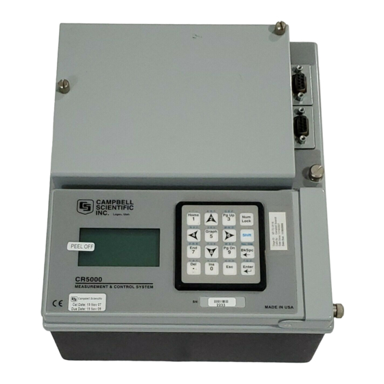
Summary of Contents for Campbell CR5000
-
Page 1: Control System
CR5000 Measurement and Control System Revision: 11/06 C o p y r i g h t © 2 0 0 0 - 2 0 0 6 C a m p b e l l S c i e n t i f i c ,... - Page 2 Warranty and Assistance The CR5000 MEASUREMENT AND CONTROL SYSTEM is warranted by CAMPBELL SCIENTIFIC, INC. to be free from defects in materials and workmanship under normal use and service for thirty-six (36) months from date of shipment unless specified otherwise. Batteries have no warranty.
-
Page 3: Table Of Contents
Protection from the Environment ................... 1-1 Power Requirements ......................1-1 CR5000 Power Supplies......................1-2 Solar Panels........................... 1-4 Direct Battery Connection to the CR5000 Wiring Panel ............1-4 Vehicle Power Supply Connections..................1-4 CR5000 Grounding ........................ 1-6 Powering Sensors and Peripherals ..................1-9 Controlling Power to Sensors and Peripherals.............. - Page 4 CR5000 TABLE OF CONTENTS CR5000 MEASUREMENT DETAILS Analog Voltage Measurement Sequence ................3-1 Single Ended and Differential Voltage Measurements ............3-4 Signal Settling Time ....................... 3-5 Thermocouple Measurements ....................3-7 Bridge Resistance Measurements..................3-17 Measurements Requiring AC Excitation ................3-19 Pulse Count Measurements....................
-
Page 5: Ov1. Physical Description
The CR5000 provides precision measurement capabilities in a rugged, battery-operated package. The system makes measurements at a rate of up to 5,000 samples/second with 16-bit resolution. The CR5000 includes CPU, keyboard display, power supply, and analog and digital inputs and outputs. The on-board, BASIC-like programming language includes data processing and analysis routines. - Page 6 MADE IN USA PCMCIA PC CARD POWER UP SDI-12 12 V CardOut (Data Tables PowerOff and Output) (program control) SDM CONNECTIONS SWITCHED 12 VOLTS SW-12 CS7500 PortSet CSAT3 SW12 SDMINT8 SDMSpeed SDMTrigger FIGURE OV1-2. CR5000 Panel and Associated Instructions. OV-2...
- Page 7 The G and 12V terminals on the unplugable Power In connector are for connecting power from an external battery to the CR5000. These are the only terminals that can be used to input battery power; the other 12V and SW-12V terminals are out only.
-
Page 8: Ov1.2 Communication And Data Storage
(PowerOff, Section 9). When the CR5000 is in this power off state the ON Off switch is in the on position but the CR5000 is off. If the "<0.5 " input is switched to ground or if the ">2" input has a voltage greater than 2 volts applied, the CR5000 will awake, load and run the “run on power-up”... -
Page 9: Ov1.3 Power Supply And Ac Adapter
CR5000 Overview OV1.3 Power Supply and AC Adapter The CR5000 has two base options the low profile without any power supply and the lead acid battery power supply base. The low profile base requires an external DC power source connected to the Power In terminal on the panel. -
Page 10: Ov2.3 Data Tables
CR5000 Overview OV2.3 Data Tables The CR5000 can store individual measurements or it may use its extensive processing capabilities to calculate averages, maxima, minima, histogams, FFTs, etc., on periodic or conditional intervals. Data are stored in tables such as listed in Table OV2-1. The values to output are selected when running the program generator or when writing a datalogger program directly. -
Page 11: Ov3.3 Pc9000 Software Overview
This overview points out the main PC9000 functions and where to find them. PC9000 has extensive on-line help to guide the user in its operation, run PC9000 to get the details. A CR5000 is not necessary to try out the programming and real time display options; a demo uses canned data for viewing. - Page 12 Save and Download Logger Files . . . Diagnostics Display Data Graph 1 . . . Display Data in Tables Collected From CR5000. Display Data Graph 2 . . . Graphing requires no special processing of the data ID2000 . . .
- Page 13 CR5000 program, wiring diagram, output table, description, and configuration file. Program Editor Create programs directly or edit those created by the program generator or retrieved from the CR5000. Provides context-sensitive help for the CR5000's BASIC-like language. OV3.3.2 Edit REALTIME Virtual Meter Updates up to five displays simultaneously.
- Page 14 Handles files of unlimited size. Historical graphing requires no special processing of the data and provides rapid feedback to the operator. OV3.3.4 Tools Control and Communications Supports PC to CR5000 communications: clock read/set, status read, program download, and program retrieval. OV3.3.5 Collect Collect data from CR5000 data tables OV3.3.6 Display...
-
Page 15: Ov4. Keyboard Display
CR5000 Overview OV4. Keyboard Display Power Up Screen Adjust contrast with < > CAMPBELL < lighter darker > SCIENTIFIC CR5000 Datalogger 06/18/2000, 18:24:35 Real Time Tables CPU: TRIG.CR5 Real Time Custom Running. Final Storage Data Reset Data Tables Graph Setup... -
Page 16: Ov4.1 Data Display
CR5000 Overview OV4.1 Data Display Data Run/Stop Program File Status List of Data Tables created by Configure, Settings active program Cursor to Data List of Data Tables created by and Press active program Enter Real Time Tables Real Time Custom... - Page 17 CR5000 Overview OV4.1.1 Real Time Tables List of Data Tables created by active program. For Example, Table1 Temps Public Cursor to desired Table and press Enter Public Table values can be changed. Tref : 23.0234 Tref : 23.0234 Cursor to value and TCTemp(1) : 19.6243...
- Page 18 CR5000 Overview OV4.1.2 Setting up Real Time Custom Display List of Data Tables created by active program. For Example, Table1 Temps Public Cursor to desired Table and Press Enter Cursor to position for next value and Press Enter Tref TCTemp(1)
- Page 19 CR5000 Overview OV4.1.3 Final Storage Tables List of Data Tables created by active program. For Example: Table1 Temps Cursor to desired Use Hm (oldest), End (newest), Table and Press PgUp (older), PgDn (newer), ← → ↑ ↓ Enter , and to move around in data table.
-
Page 20: Ov4.2 Run/Stop Program
No Program Run/Stop Program CRD: File List of Programs Status Configure, Settings You may now remove the Card. CR5000 closes tables first. Cursor to PCCard and Press Enter All Card Data Will be Lost! Remove Card Proceed? Format Card Table Status... -
Page 21: Ov4.3 File Display
CR5000 Overview OV4.3 File Display Data Run/Stop Program File Status Configure, Settings New File Name: CPU: .CR5 CRD: .CR5 Cursor to File and CPU: Press Enter CRD: Edit Copy Delete Copy Run Options From Directory Format Execute List of files on CPU or Card. - Page 22 CR5000 Overview OV4.3.1 File: Edit The Program Editor in PC9000 is recommended for writing and editing datalogger programs. Changes in the field can be made with the keyboard display. List of Program files on CPU: or CRD: For Example: CPU: TCTEMP.CR5...
-
Page 23: Ov4.4 Configure Display
CR5000 Overview OV4.4 Configure Display 05/24/2000, 15:10:40 Data Year 2000 Run/Stop Program Month File Status Hour Configure, Settings Minute Cancel Cursor to Security Enable Enter Passwords: Enter Configure, click RS-232 Time Out: No Level 1: Settings and CR5000 Off Level 2:... -
Page 24: Ov5. Specifications
PROGRAM EXECUTION RATE RESISTANCE MEASUREMENTS EMI and ESD PROTECTION The CR5000 can measure one channel and store the The CR5000 is encased in metal and incorporates Provides voltage ratio measurements of 4- and 6-wire result in 500 µs; all 40 SE* channels can be measured EMI filtering on all inputs and outputs. -
Page 25: Protection From The Environment
18½"x18¾"x10½" (with brackets); weight is 18 lbs. 1.2 Power Requirements The CR5000 operates at a nominal 12 VDC. Below 11.0 V or above 16 volts the CR5000 does not operate properly. The CR5000 is diode protected against accidental reversal of the positive and ground leads from the battery. -
Page 26: Cr5000 Power Supplies
The red light (LED) on the base is on during charging with 17 to 24 VDC or 18 V RMS AC. The switch turns power to the CR5000 on or off. Battery charging still occurs when the switch is off. - Page 27 If the system voltage level consistently decreases through time, some element(s) of the charging system has failed. Battery measures the voltage at the CR5000 electronics, not the voltage of the lead acid battery. The measured voltage will normally be about 0.3 V less than the voltage at the internal or external 12 V input.
-
Page 28: Solar Panels
1.6 Vehicle Power Supply Connections 1.6.1 CR5000 with Battery Base The best way to power a CR5000 with battery base from a vehicle’s 12 V power system is to use the DCDC18R to input the power to the CR5000’s charger input (Figure 1.6-1). With this configuration the CR5000’s batteries are charged when the vehicle power is available. - Page 29 It is also possible to use the vehicle's 12 V power system as the primary supply for a CR5000 with a battery base (Figure 1.6-2). When a vehicle’s starting motor is engaged, the system voltage drops considerably below the 11 volts needed for uninterrupted datalogger function.
-
Page 30: Cr5000 Grounding
Section 1. Installation and Maintenance 1.6.2 CR5000 with Low Profile Base (No Battery) If a CR5000 without batteries is to be powered from the 12 Volts of a motor vehicle, a second 12 V supply is required. When the starting motor of a... - Page 31 ADE IN USA FIGURE 1.7-1. Schematic of CR5000 Grounds The 9-pin serial I/O ports on the CR5000 are another path for transients to enter and damage the CR5000. Communications devices such a telephone or short-haul modem lines should have spark gap protection. Spark gap protection is often an option with these products, so it should always be requested when ordering.
- Page 32 Common mode range for the CR5000 is ±5.0 V. For example, if the high side of a differential input is at 2 V and the low side is at 0.5 V relative to CR5000 ground, a measurement made on the ±5.0 V range would indicate a signal of 1.5 V.
-
Page 33: Powering Sensors And Peripherals
Voltage on the 12V and SW-12 terminals will change with the CR5000 supply voltage. The 5V terminal is regulated and will always remain near 5 Volts ( 4%)so long as the CR5000 supply voltage remains above 11 Volts. The 5V terminal is not suitable for resistive bridge sensor excitation. Table 1.8-1 shows the current limits of the 12 Volt and 5 Volt ports. -
Page 34: Controlling Power To Sensors And Peripherals
5V + CSI/O < 200 mA Make certain that the primary source of power for the CR5000 can sustain the current drain for the period of time required. Contact a CSI applications engineer for help in determining a power budget for applications that approach the limits of a given power supply’s capabilities. - Page 35 (Figure 1.9-1) would be required. Other control port activated circuits are possible for applications with greater current/voltage demands than shown in Figures 1.9-1 and 2. For more information contact a Campbell Scientific applications engineer. FIGURE 1.9-1. Relay Driver Circuit with Relay 1-11...
-
Page 36: Maintenance
CR5000 is not powered. The CR5000 does not draw any power from the lithium battery while it is powered by a 12 VDC supply. In a CR5000 stored at room temperature, the lithium battery should last approximately 10 years (less at temperature extremes). - Page 37 Section 1. Installation and Maintenance While powered from an external source, the CR5000 measures the voltage of the lithium battery daily. This voltage is displayed in the status table (Section 1.6) A new battery will have approximately 3.6 volts. The CR5000 Status Table has a “...
- Page 38 Section 1. Installation and Maintenance The new cell is placed into the battery holder, observing the polarity markings on the holder. Replace the band clamp, ensuring that both ends snap securely into the battery holder. B A T T E R Y 2 (datalogger/ c r5 0 00) FIGURE 1.10-5.
- Page 39 Section 1. Installation and Maintenance FIGURE 1.11-6. Removal of band clamp and battery. 1-15...
- Page 40 Section 1. Installation and Maintenance This is a blank page. 1-16...
-
Page 41: Data Storage In Cr5000
2.1.2 PCMCIA PC Card The CR5000 has a built in PC card slot for a Type I, Type II, or Type III PCMCIA card. PCMCIA PC Cards allows expanding the CR5000’s storage capacity. SRAM and ATA cards are supported. A program can send a... -
Page 42: Internal Data Format
If the card has adequate space, the tables will be allocated and the CR5000 will start storing data to them. If there is no card or if there is not enough space, the CR5000 will warn that the card is not being used and will run the program, storing the data in SRAM only. -
Page 43: Data Collection
PC card from the PC9000 to the computer. There are three ways to collect data via a link to the CR5000 using the PC9000 software. The collect menu is used to collect any or all stored data and is used for most archival purposes. - Page 44 All Records, Create New File – Collects the entire table stored in the CR5000. PC9000 gets the current record number from the table in the CR5000 and then retrieves the oldest record in the table up to the current record number.
- Page 45 (see Table naming). This is a convenient method of collecting all data from the CR5000. The first time data are collected, all data is checked and the file type and collection method are selected. PC9000 remembers the settings, and on subsequent collections the operator only needs to click on execute.
-
Page 46: Status Messages
Write File box is unchecked or until the window is closed. This collection method requires that the PC is connected to the CR5000 while the data are collected. Because the beginning and end points of the data file... -
Page 47: Logger Files Retrieve
FIGURE 2.3-2. Logger Files Dialog Box 2.3.4 Via PCMCIA PC Card When the CR5000 is used without a computer in the field, or large data files are collected on a PC card, the PC card can be transported to the computer with the data on it. - Page 48 CR5000. When a new program is compiled that sends data to the PC card, the CR5000 checks if a card is present and if the card has adequate space for the data tables. If the card has adequate space, the tables will be allocated and the CR5000 will start storing data to them.
- Page 49 2.3.4.3 Converting File Format The CR5000 stores data on the PC card in TOB2 Format. TOB2 is a binary format that incorporates features to improve reliability of the PC Cards. TOB2 allows the accurate determination of each record’s time without the space required for individual time stamps.
-
Page 50: Data Format On Computer
Logger Serial Number The serial number of the logger that the data was collected from. This is the serial number of the CR5000 CPU. Operating System Version The version of the operating system in the logger that the data was collected from. -
Page 51: Toa5 Ascii File Format
Section 2. Data Storage and Retrieval Field Name The name of the field in the data table. This name is created by the CR5000 by appending underscore ( _ ) and a three character mnemonic for the output processing. Field Units The units for the field in the data table. -
Page 52: Tob1 Binary File Format
Section 2. Data Storage and Retrieval The following is an example of how the above data might look when imported into a spread sheet. TOA5 Bob's9K CR5000 1048575 1.00 EXPLDAT. 4339 Temp TIMESTAMP RECORD RefTemp_Avg TC_Avg(1) TC_Avg(2) TC_Avg(3) TC_Avg(4) degC... - Page 53 Section 2. Data Storage and Retrieval stamped, allowing the calculation of time stamps for their records. If there is a lapse in periodic interval records that does not occur on a frame boundary, an additional time stamp is written within the frame and its occurrence noted in the frame boundary.
- Page 54 Section 2. Data Storage and Retrieval This is a blank page. 2-14...
-
Page 55: Analog Voltage Measurement Sequence
(Integ), and to reverse the polarity of excitation voltage (RevEx). 3.1.1 Voltage Range The CR5000 has 5 fixed voltage ranges and autorange. The 16 bit A/D has a resolution of 1 part in 2 (65,536). To allow for some overrange capabilities the A/D is applied to a range approximately 9% greater than the Full Scale Range resulting in the 1 part in 60,000 resolution over the FSR. - Page 56 In most cases the background calibration is adequate. Additional accuracy can be gained by making the offset measurement with each measurement instruction when the offset is changing rapidly as it would during when the CR5000 is undergoing rapid temperature swings.
- Page 57 Section 3. CR5000 Measurement Details 3.1.4 SettlingTime When the CR5000 switches to a new channel or switches on the excitation for a bridge measurement, there is a finite amount of time required for the signal to reach its true value. Delaying between setting up a measurement (switching to the channel, setting the excitation) and making the measurement allows the signal to settle to the correct value.
-
Page 58: Single Ended And Differential Voltage Measurements
500 µs, the CR5000 will repeat 250 µs integration measurements every 500 s throughout the integration interval. If the integration time specified is 100 µs or 200 µs, the CR5000 makes one or two samples in the integration interval. The average of these measurements is stored as the result of the measurement. -
Page 59: Signal Settling Time
Section 3. CR5000 Measurement Details be made. For example, if the high side of a differential input is at 4 V and the low side is at 3 V relative to CR5000 ground, there is no problem. A ± measurement made on the 5000 mV range will return 1000 mV. -
Page 60: Minimizing Settling Errors
CR5000. 3.3.2 Measuring the Necessary Settling Time The CR5000 can measure the time required for a particular sensor/cable configuration to settle. This is done by allowing the signal to settle the minimum amount of time and then making zero integration measurements every 100 s. -
Page 61: Thermocouple Measurements
EndTable 'The following program repeats the 20 measurements 5 times: BeginProg Scan (1,Sec,3,5) 'The -1 in the differential channel parameter of BrFull tells 'the CR5000 to make the 20 measurements on channel 1: BrFull (PT(),20,mV50,-1,Vx1,20,5000,False,False,0,0,1.0,0) CallTable SetlDat NextScan EndProg The program was run on a Druck water level pressure transducer with 200 feet of cable. -
Page 62: Error Analysis
Panel Temperature A brass bar is just under the CR5000 panel between the two rows of analog input terminals. This bar helps to reduce temperature gradients between the terminals. The panel temperature thermistor is in a depression in the center of this bar. - Page 63 45 minutes, a less dramatic change but still greater than would be seen in most natural circumstances. During these rapid changes in temperature, the temperature of panel thermistor will tend to lag behind the terminals because it is buried a bit deeper in the CR5000 and is closer to the...
- Page 64 Section 3. CR5000 Measurement Details thermal mass of the batteries. Note that the smallest errors are on channels 5 and 16 in the middle of the terminal strips closest to the thermistor. Reference Temperature Errors Due to Panel Gradient Chamber changed from -55 to 80 °C at maximum rate...
-
Page 65: Thermocouple Limits Of Error
Section 3. CR5000 Measurement Details Reference Temperature Errors Due to Panel Gradient Chamber Changed From 80 to 25 °C at 1.3 °C/Minute Channel 1 Channel 5 Channel 10 Channel 11 Channel 16 Channel 20 Panel Chamber -0.2 -0.4 Time (minutes) FIGURE 4.3-3. - Page 66 0.25% added on, to the difference in temperature being measured by the thermocouple. Accuracy of the Thermocouple Voltage Measurement The -25 to 50 °C accuracy of a CR5000 differential voltage measurement is specified as (0.075% of the measured voltage plus the input offset error of 2 times the basic resolution of the range being used to make the measurement plus 2 V).
- Page 67 NIST Monograph 175 gives high order polynomials for computing the output voltage of a given thermocouple type over a broad range of temperatures. In order to speed processing and accommodate the CR5000's math and storage capabilities, 4 separate 6th order polynomials are used to convert from volts to temperature over the range covered by each thermocouple type.
- Page 68 The ranges covered by these linearizations include the CR5000 environmental operating range, so there is no problem when the CR5000 is used as the reference junction. External reference junction boxes however, must also be within these temperature ranges.
- Page 69 The magnitude of the errors described in the previous sections illustrate that the greatest sources of error in a thermocouple temperature measurement with the CR5000 are likely to be due to the limits of error on the thermocouple wire and in the reference temperature. Errors in the thermocouple and reference temperature linearizations are extremely small, and error in the voltage measurement is negligible.
- Page 70 Section 3. CR5000 Measurement Details the box to the CR5000. Alternatively, the junction box can be used to couple extension grade thermocouple wire to the thermocouples, and the CR5000 panel temperature used as the reference. Extension grade thermocouple wire has a smaller temperature range than standard thermocouple wire, but meets the same limits of error within that range.
-
Page 71: Bridge Resistance Measurements
3.5 Bridge Resistance Measurements There are six bridge measurement instructions included in the standard CR5000 software. Figure 3.5-1 shows the circuits that would typically be measured with these instructions. In the diagrams, the resistors labeled R would normally be the sensors and those labeled R would normally be fixed resistors. - Page 72 Section 3. CR5000 Measurement Details BrHalf4W X = result w/mult = 1, offset = 0 BrFull X = result w/mult = 1, offset = 0 1000 1000 1000 BrFull6W X = result w/mult = 1, offset = 0 1000 1000...
-
Page 73: Measurements Requiring Ac Excitation
This ground loop arises because the soil and water provide an alternate path for the excitation to return to CR5000 ground, and can be represented by the model diagrammed in Figure 3.6-1. -
Page 74: Pulse Count Measurements
The ground electrode of the conductivity or soil moisture probe and the CR5000 earth ground form a galvanic cell, with the water/soil solution acting as the electrolyte. If current was allowed to flow, the resulting oxidation or reduction would soon damage the electrode, just as if DC excitation was used to make the measurement. -
Page 75: Self Calibration
The CR5000 performs a self-calibration of the analog voltage measurements and excitation voltages. The range gains and offsets and the excitation voltage output will vary with temperature. The self calibration allows the CR5000 to maintain its specifications over the temperature range. - Page 76 1% of reading. Temperature is the main factor causing a calibration shift and the need for the self calibration. If the temperature of the CR5000 remains the same there will be little calibration drift with the self calibration disabled.
-
Page 77: Crbasic - Native Language Programming
Section 4. CRBasic - Native Language Programming The CR5000 is programmed in a language that has some similarities to a structured basic. There are special instructions for making measurements and for creating tables of output data. The results of all measurements are assigned variables (given names). -
Page 78: Programming Sequence
Comments can be inserted into a program by preceding the comment with a single quote ('). Comments can be entered either as independent lines or following CR5000 code. When the CR5000 compiler sees the ' it ignores the rest of the line. - Page 79 Section 4. CRBasic - Native Language Programming Define Subroutines If there is a process or series of calculations that need to be repeated several times in the program, it can be packaged in a subroutine and called when needed rather than repeating all the code each time.
-
Page 80: Example Program
Alternatively, the FieldNames instruction can be used to override the default names. The data table header also has a row that lists units for the output values. The units must be declared for the CR5000 to fill this row out (e.g., Units RefTemp... - Page 81 The DataTable instruction has three parameters: a user specified name for the table, a trigger condition, and the size to make the table in CR5000 RAM. The trigger condition may be a variable, expression, or constant. The trigger is true if it is not equal to 0.
- Page 82 TABLE 4.3-1 Formats for Output Data Code Data Format Size Range Resolution Campbell Scientific floating point 2 bytes 7999 13 bits (about 4 digits) IEEE4 IEEE four byte floating point 4 bytes 1.8 E -38 to 1.7 E 38...
-
Page 83: Numerical Entries
Table 4.5-1. The CR5000 evaluates the test or parameter as a number; 0 is false, not equal to 0 is true. -
Page 84: Flags
W equal to -1 if X>Y or will set W equal to 0 if X<=Y. The CR5000 uses -1 rather than some other non-zero number because the and and or operators are the same for logical statements and binary bitwise comparisons (see and and or in Section 8). -
Page 85: Parameter Types
Section 4. CRBasic - Native Language Programming 4.7 Parameter Types Instructions parameters allow different types of inputs these types are listed below and specifically identified in the description of the parameter in the following sections or in PC9000 CRBasic help. Constant Variable Variable or Array... -
Page 86: Program Access To Data Tables
Section 4. CRBasic - Native Language Programming calibrated sensors, applying the correct calibration to each sensor. If the multiplier and offset are not arrays, the same multiplier and offset are used for each repetition. VoltSE(Dest,Reps,Range,ASlot,SEChan,Delay, Integ,Mult,Offset) 'Calibration factors: Mult(1)=0.123 : Offset(1)= 0.23 Mult(2)=0.115 : Offset(2)= 0.234 Mult(3)=0.114 : Offset(3)= 0.224 VoltSE(Pressure(),3,mV1000,6,1,1,100,Mult(),Offset() - Page 87 Section 4. CRBasic - Native Language Programming Tablename.eventend(1,1) is only valid for a data table using the DataEvent instruction, Tablename.eventend(1,1) = 1 if the last record of an event occurred the last time the table was called, = 0 if the data table did not store a record or if it is in the middle of an event.
- Page 88 Section 4. CRBasic - Native Language Programming This is a blank page. 4-12...
-
Page 89: Program Declarations
Section 5. Program Declarations Alias Used to assign a second name to a variable. Syntax Alias VariableA = VariableB Remarks Alias allows assigning a second name to a variable. Within the datalogger program, either name can be used. Only the alias is available for Public variables. The alias is also used as the root name for data table fieldnames. - Page 90 When variables are initialized, they are initialized to 0 Put Dim statements at the beginning of the program. Public Dimensions a variable as public and available in the Public table of the CR5000. Syntax Public( list of [dimensioned] variables that make up the Public Table Remarks More than one Public statement can be made.
- Page 91 Data Table Info file of PC9000. The unit name is a text field that allows the user to label data. When the user modifies the units, the text entered is not checked by PC9000 or the CR5000. Example...
- Page 92 Section 5. Program Declarations The Sub statement has these parts: Part Description Marks the beginning of a Subroutine. SubName Name of the Subroutine. Because Subroutine names are recognized by all procedures in all modules, subname cannot be the same as any other globally recognized name in the program.
- Page 93 Section 5. Program Declarations Subroutine Example 'CR5000 'Declare Variables used in Program: Public RefT, TC(4),PRTresist,PRTtemp,I 'Data output in deg C: DataTable (TempsC,1,-1) DataInterval (0,5,Min,10) Average (1,RefT,FP2,0) Average (4,TC(),FP2,0) Average (1,PRTtemp,FP2,0) EndTable 'Same Data output in F: DataTable (TempsF,1,-1) DataInterval (0,5,Min,10)
- Page 94 Section 5. Program Declarations This is a blank page.
-
Page 95: Data Table Declaration
Section 6. Data Table Declarations and Output Processing Instructions 6.1 Data Table Declaration DataTable (Name, TrigVar, Size) output trigger modifier export data destinations output processing instructions EndTable DataTable is used to declare/define a data table. The name of the table, output trigger and size of the table in RAM are set with DataTable. -
Page 96: Trigger Modifiers
Interval driven data allows a more efficient use of memory because it is not necessary to store time with each record. The CR5000 still stores time but on a fixed spacing, only about once per 1 K of memory used for the table. As each new record is stored, time is checked to ensure that the interval is correct. - Page 97 Constant OpenInterval When the DataInterval instruction is included in a data table, the CR5000 uses only values from within an interval for time series processing (e.g., average, maximum, minimum, etc.). When data are output every interval, the output processing instructions reset each time output occurs.
- Page 98 The variable, expression or constant to test to stop storing to the data table. The Variable, CR5000 does not start checking for the stop trigger until after the Start Trigger Expression or occurs. A non-zero (true) constant may be used to store a fixed number of...
- Page 99 Section 6. Data Table Declarations and Output Processing Instructions DataEvent Example: In this example, 5 type T thermocouples are measured. The trigger for the start of an event is when TCTemp(1) exceeds 30 degrees C. The stop trigger is when TCTemp(1) less than 29 degrees C. The event consists of 20 records prior to the start trigger and continues to store data until 10 records following the stop trigger.
- Page 100 Section 6. Data Table Declarations and Output Processing Instructions WorstCase (TableName, NumCases, MaxMin, Change, RankVar) Allows saving the most significant or “ worst-case” events in separate data tables. A data table is created that is sized to hold one event. This table acts as the event buffer.
- Page 101 Section 6. Data Table Declarations and Output Processing Instructions WorstCase Example This program demonstrates the Worst Case Instruction. Five type T thermocouples are measured. The event is similar to that in the example for the DataEvent instruction; the trigger for the start of a data event is when TC(1) exceeds 30 degrees C.
-
Page 102: Export Data Instructions
Section 6. Data Table Declarations and Output Processing Instructions 6.3 Export Data Instructions CardOut (StopRing, Size) Used to send output data to the PCMCIA card. This instruction creates a data table on the PCMCIA card. CardOut must be entered within each data table declaration that is to store data on a PCMCIA card. - Page 103 Section 6. Data Table Declarations and Output Processing Instructions Data transfer to the transmitter can occur via the datalogger's CS I/O port only. The GOESData instruction has the following parameters: NOTE When the datalogger sends a command, further processing tasks will be performed only after a response has been received from the HDR GOES Transmitter.
- Page 104 Section 6. Data Table Declarations and Output Processing Instructions Parameter Enter & Data Type DataFormat The DataFormat parameter specifies the format of the data sent to the transmitter Constant Code Description CSI FP2 data; 3 bytes per data point Floating point ASCII; 7 bytes per data point 18-bit binary integer;...
-
Page 105: Output Processing Instructions
Data Format IEEE4 IEEE 4 byte floating point Campbell Scientific 2 byte floating point DisableVar A non-zero value will disable intermediate processing. Normally 0 is entered so all inputs are processed. For example, in the Average instruction, when the disable variable is 0 Constant, the current input is not included in the average. - Page 106 Numeric Code Data Format IEEE4 IEEE 4 byte floating point Campbell Scientific 2 byte floating point DisableVar A non-zero value will disable intermediate processing. When the disable variable is 0 the current input is not included in the Covariance. Constant,...
- Page 107 Section 6. Data Table Declarations and Output Processing Instructions Parameter Enter & Data Type Units The units for Tau. Constant Alpha Numeric Code Code Units USEC microseconds MSEC milliseconds seconds minutes Options A code to indicate what values to calculate and output. Constant Code Result...
- Page 108 Section 6. Data Table Declarations and Output Processing Instructions Notes: Power is independent of the sampling rate (1/tau) and of the number of samples (N). The PSD is proportional to the length of the sampling period (T=N*tau), since the “ width” of each bin is 1/T. The sum of the AC bins (excluding DC) of the Power Spectrum is the Variance (AC Power) of the time series.
- Page 109 FieldNames “list of fieldnames” The FieldNames instructions may be used to override the fieldnames that the CR5000 generates for results sent to the data table. Fieldnames must immediately follow the output instruction creating the data fields. Field names are limited to 19 characters. Individual names may be entered for each result generated by the previous output instruction or an array may be used to name multiple fields.
- Page 110 Section 6. Data Table Declarations and Output Processing Instructions Sample(4, Temp(1), IEEE4) FieldNames “ IntakeT(2)” The 4 values from the variable array Temp are stored in the output table with IntakeT,an array of 2, and the remainder of the default array Temp: IntakeT(1), IntakeT(2), Temp(3), and Temp(4), Histogram (BinSelect, DataType, DisableVar, Bins, Form, WtVal, LoLim, UpLim)
- Page 111 Data Format IEEE4 IEEE 4 byte floating point Campbell Scientific 2 byte floating point DisableVar A non-zero value will disable intermediate processing. Normally 0 is entered so all inputs are processed. For example, when the disable variable is 0 the current input is not Constant, included in the histogram.
- Page 112 Section 6. Data Table Declarations and Output Processing Instructions Histogram4D (BinSelect, Source, DataType, DisableVar, Bins1, Bins2, Bins3, Bins4, Form, WtVal, LoLim1, UpLim1, LoLim2, UpLim2, LoLim3, UpLim3, LoLim4, UpLim4) Processes input data as either a standard histogram (frequency distribution) or a weighted value histogram of up to 4 dimensions. The description of the Histogram instruction also applies to the Histogram4D instruction.
- Page 113 Data Format IEEE4 IEEE 4 byte floating point Campbell Scientific 2 byte floating point A non-zero value will disable intermediate processing. Normally 0 is entered so all inputs DisableVar are processed. For example, when the disable variable is 0 the current input is not Constant, included in the histogram.
- Page 114 Section 6. Data Table Declarations and Output Processing Instructions Processes data with the Level Crossing counting algorithm. The output is a two dimensional Level Crossing Histogram. One dimension is the levels crossed; the second dimension, if used, is the value of a second input at the time the crossings were detected.
- Page 115 Section 6. Data Table Declarations and Output Processing Instructions Point Source Action Bin 1 Bin 2 Bin 3 (level=1) (level=1.5) (level=3) First value, no counts Add one count to first bin, the signal crossed 1 No levels crossed, no counts Crossed a level but was falling edge, no counts...
- Page 116 Section 6. Data Table Declarations and Output Processing Instructions Point Crossing 2nd Dim Action Source Source First value, no counts Add one count to first crossing, second 2D bin, the signal crossed Histogram: 2D < 1.25 1.25<2D<2.25 2.25<2D<3.25 Cross 1 Cross 1.5 Cross 3 No levels crossed, no counts...
- Page 117 Data Format IEEE4 IEEE 4 byte floating point Campbell Scientific 2 byte floating point DisableVar A non-zero value will disable intermediate processing. Normally 0 is entered so all inputs are processed. For example, when the disable variable is 0 the current input is not Constant, checked for a new maximum.
- Page 118 Data Format IEEE4 IEEE 4 byte floating point Campbell Scientific 2 byte floating point DisableVar A non-zero value will disable intermediate processing. Normally 0 is entered so all inputs are processed. For example, when the disable variable is 0 the current input is not Constant, checked for a new minimum.
- Page 119 Section 6. Data Table Declarations and Output Processing Instructions Parameter Enter & Data Type Form The Form code is 3 digits - ABC Constant Code Form A = 0 Reset histogram after each output. A = 1 Do not reset histogram. B = 0 Divide bins by total count.
- Page 120 Numeric Code Data Format IEEE4 IEEE 4 byte floating point Campbell Scientific 2 byte floating point StdDev (Reps, Source, DataType, DisableVar) StdDev calculates the standard deviation of the Source(s) over the output interval. x is the standard deviation of x, and N is the number of samples...
- Page 121 Numeric Code Data Format IEEE4 IEEE 4 byte floating point Campbell Scientific 2 byte floating point DisableVar A non-zero value will disable intermediate processing. Normally 0 is entered so all inputs Constant, are processed. For example, when the disable variable is 0 the current input is not Variable, or included in the standard deviation.
- Page 122 Resultant mean wind speed, Resultant mean wind direction, u. Standard deviation of wind direction, ( u). This standard deviation is calculated using Campbell Scientific's wind speed weighted algorithm. Use of the Resultant mean horizontal wind direction is not recommended for straight-line Gaussian dispersion models, but may be used to model transport direction in a variable-trajectory model.
-
Page 123: Measured Raw Data
Section 6. Data Table Declarations and Output Processing Instructions When used with polar sensors, the instruction does a modulo divide by 360 on wind direction, which allows the wind direction (in degrees) to be 0 to 360, 0 to 540, less than 0, or greater than 540. The ability to handle a negative reading is useful where a difficult to reach wind vane is improperly oriented. - Page 124 Section 6. Data Table Declarations and Output Processing Instructions Calculations: North East FIGURE 6.4-2. Input Sample Vectors In Figure 6.4-2, the short, head-to-tail vectors are the input sample vectors described by , the sample speed and direction, or by Ue and Un , the east and north components of the sample vector.
- Page 125 Ue=( Ue Un=( Un Resultant mean wind direction, u: u=Arctan (Ue/Un) Standard deviation of wind direction, ( u), using Campbell Scientific algorithm: ( u)=81(1- The algorithm for ( u) is developed by noting (Figure 6.4-4) that U / s ; where FIGURE 6.2-3.
- Page 126 Section 6. Data Table Declarations and Output Processing Instructions For deviations less than 40 degrees, the error in this approximation is less than 1%. At deviations of 60 degrees, the error is 10%. The speed sample may be expressed as the deviation about the mean speed, s' S Equating the two expressions for Cos ( ‘) and using the previous equation for ' ) /...
-
Page 127: Voltage Measurements
Section 7. Measurement Instructions 7.1 Voltage Measurements VoltDiff – Differential Voltage Measurement..........7-3 VoltSE – Single-ended Voltage Measurement ..........7-3 7.2 Thermocouple Measurements Measure the Output of Thermocouples and Convert to Temperature. TCDiff – Differential Voltage Measurement of Thermocouple ....7-3 TCSE –... -
Page 128: Digital I/O
INT8 – Allows the use of the SDM-INT8, 8 channel interval timer, with the CR5000 ................7-39 SDMSpeed - Changes the rate that the CR5000 uses to clock the SDM data..................... 7-42 SDMTrigger - Allows the CR5000 to synchronize when measurements are made ..................... -
Page 129: Voltage Measurements
Section 7. Measurement Instructions 7.1 Voltage Measurements VoltDiff (Dest, Reps, Range, DiffChan, RevDiff, SettlingTime, Integ, Mult, Offset) Diff. Chanel H Sensor Diff. Chanel L. This instruction measures the voltage difference between the HI and Low inputs of a differential channel. Both the high and low inputs must be within ± 5V of the datalogger's ground (See Common Mode Range, Section 3.2). - Page 130 Section 7. Measurement Instructions TCSE (Dest, Reps, Range, SEChan, TCType, TRef, MeasOfs, SettlingTime, Integ, Mult, Offset) S.E. Chanel Thermocouple Ground This instruction measures a thermocouple with a single-ended voltage measurement and calculates the thermocouple temperature (°C) for the thermocouple type selected. The instruction adds the measured voltage to the voltage calculated for the reference temperature relative to 0°...
-
Page 131: Half Bridges
Section 7. Measurement Instructions Parameter Enter & Data Type RevDiff Code Value Result (Reversing requires twice as much time to complete) Signal is measured with the high side referenced to the low Constant False ≠0 A second measurement is made after reversing the inputs to cancel True offsets MeasOfs... - Page 132 Section 7. Measurement Instructions BrHalf3W (Dest, Reps, Range, SEChan, ExChan, MeasPEx, ExmV, RevEx, SettlingTime, Integ, Mult, Offset) X = result w/mult = 1, offset = 0 − − This Instruction is used to determine the ratio of the sensor resistance to a known resistance using a separate voltage sensing wire from the sensor to compensate for lead wire resistance.
- Page 133 Section 7. Measurement Instructions Half Bridge Parameters Parameter Enter & Data Type Dest The Variable in which to store the results of the instruction. When Reps are used the results are stored in an array with the variable name. An array must be dimensioned to Variable or have elements for all the Reps.
-
Page 134: Full Bridges
Section 7. Measurement Instructions Parameter Enter & Data Type SettlingTime The time in microseconds to delay between setting up a measurement (switching to the channel, setting the excitation) and making the measurement. (1 microsecond resolution) Constant Entry Voltage Range Integration Settling Time ±... - Page 135 Section 7. Measurement Instructions BrFull6W (Dest, Reps, Range1, Range2, DiffChan, ExChan, MeasPEx, ExmV, RevEx, RevDiff, SettlingTime, Integ, Mult, Offset) X = result w/mult = 1, offset = 0 ⎛ ⎞ − 1000 1000 ⎜ ⎟ ⎝ ⎠ This Instruction applies an excitation voltage and makes two differential voltage measurements.
- Page 136 Section 7. Measurement Instructions Parameter Enter & Data Type ExChan Enter the excitation channel number to excite the first measurement. Constan Alpha Code/ Result Code Channel Switched excitation channels, are switched to the excitation voltage. for the measurement and switched off between measurements. MeasPEx The number of sensors to excite with the same excitation channel before automatically advancing to the next excitation channel.
-
Page 137: Current Excitation
Section 7. Measurement Instructions 7.5 Current Excitation Resistance (Dest, Reps, Range, DiffChan, IxChan, MeasPEx, ExuA, RevEx, RevDiff, SettlingTime, Integ, Mult,Offset) The Resistance instruction applies a precision current excitation and measures a differential voltage. The result is the measured voltage divided by the excitation current. - Page 138 Section 7. Measurement Instructions Resistance used to measure full bridge X = result w/mult = 1, − − offset = 0 − − ⎛ ⎞ ⎜ − ⎟ − − bridge ⎝ ⎠ − − − Resistance Parameters Parameter Enter &...
-
Page 139: Excitation/Continuous Analog Output
Section 7. Measurement Instructions Parameter Enter & Data Type SettlingTime The time in microseconds to delay between setting up a measurement (switching to the Constant channel, setting the excitation) and making the measurement. (1 microsecond resolution) Voltage Range Integration Settling Time Entry ±... -
Page 140: Specified
Section 7. Measurement Instructions Parameter Enter & Data Type CAOChan The CAO channel to set. Constant Alpha Numeric Description CAO1 CAO channel 1 CAO2 CAO channel 2 The voltage, in millivolts, to apply to the CAO Channel. The allowable range is ±5000 CAOmV mV. -
Page 141: Self Measurements
Section 7. Measurement Instructions Parameter Enter & Data Type ExChan Enter the excitation channel number to excite the first measurement. Constan Alpha Code/ Result Code Channel Switched excitation channels, are switched to the excitation voltage. for the measurement and switched off between measurements. The excitation voltage in millivolts. - Page 142 2) The CR5000 will experience extremely rapid temperature change and the Calibration instruction is run to update the calibration before each set of measurements.
- Page 143 Section 7. Measurement Instructions Unless the AllRanges option is selected, the calibrate instruction only measures the range and integration combinations that occur in the measurements in the program. For the 250 µs and zero integration calibrations multiple measurements are averaged for the calibration values. The 250 µs integration calibration averages five measurements and the zero integration calibration averages ten measurements.
- Page 144 Section 7. Measurement Instructions 250 µSec integrate 1000 mV differential offset 250 µSec integrate 1000 mV gain 250 µSec integrate 200 mV single ended offset 250 µSec integrate 200 mV differential offset 250 µSec integrate 200 mV gain 250 µSec integrate 50 mV single ended offset 250 µSec integrate 50 mV differential offset 250 µSec integrate 50 mV gain 250 µSec integrate 20 mV single ended offset...
- Page 145 The voltage in millivolts that the input must cross for a count to occur. For a signal Threshold centered around CR5000 ground (Figure 7.8-1) the threshold should be 0. If the input Constant signal is a 0 to 5 V CMOS signal then a threshold of 2500 mV would result in the voltage comparator switching at 2.5 V.
- Page 146 For sensor amplitudes less than 20 mV pk-pk a dc blocking capacitor, see Figure 7.8-1, is recommended to center the signal at CR5000 ground (threshold = 0) because of offset voltage drift along with limited accuracy (± 10 mV) and resolution (1.2 mV) of a threshold other than 0.
- Page 147 Section 7. Measurement Instructions The back-to-back silicon diodes D1 and D2 provide ESD protection of capacitor C and the sensor, and also limit the amplitude of large amplitude sensor signals. These diodes clip large amplitude signals to approximately 1.4 V pk-pk which is within the recommended input signal ranges for all range codes.
- Page 148 Section 7. Measurement Instructions Parameter Enter & Data Type Dest The variable in which to store the result of the instruction. A 1 is stored if the port is high; 0 is stored if the port is low. Variable The control port number (1-8) for which the status should be obtained. Port Constant PortGet Example...
- Page 149 Section 7. Measurement Instructions PulseCount (Dest, Reps, PChan, PConfig, POption, Mult, Offset) Pulse Channel Sensor Ground Parameter Enter & Data Type Dest The Variable in which to store the results of the instruction. When Reps are used the results are stored in an array with the variable name. An array must be dimensioned Variable or to have elements for all the Reps.
- Page 150 FIGURE 7.8-1. Conditioning Large Voltage Pulses The maximum input voltage on a pulse channel is ±20 V. Refer to Figure 7.8-1 if reducing input voltage is required. • CR5000 Pulse Channels Maximum Input Voltage: ±20 V High Frequency Input •...
- Page 151 ReadIO is used to read the status of selected control I/O channels (ports) on the CR5000. There are 8 ports. The status of these ports is considered to be a binary number with a high port (+5 V) signifying 1 and a low port (0 V) signifying 0.
- Page 152 Section 7. Measurement Instructions SW12 The SW12 instruction is used to set a Switched 12 volt supply high or low. Syntax SW12( State ) Remarks The datalogger has a switched 12 volt output with two terminals. This switched 12 volts is used to provide a continuous 12 volt supply to external peripherals. At room temperature the switched 12 volt supply can source 900 mA between the SW-12 terminal and Ground.
- Page 153 Section 7. Measurement Instructions TimerIO The TimerIO instruction is used to measure the time between edges (state transitions) or frequency on the digital I/O ports of the datalogger. The timing resolution is 50 nanoseconds. The longest interval that can be timed is 214.7 seconds (2 x 50 nanoseconds).
- Page 154 WriteIO is used to set the status of selected control I/O channels (ports) on the CR5000. (See Also PortSet.) There are 8 ports. The status of these ports is considered to be a binary number with a high port (+5 V) signifying 1 and a low port (0 V) signifying 0.
-
Page 155: Peripheral Devices
Section 7. Measurement Instructions 7.9 Peripheral Devices AM25T (Dest, Reps, Range, AM25TChan, DiffChan, TCType, Tref, ClkPort, ResPort, VxChan, RevDiff, SettlingTime, Integ, Mult, Offset) This Instruction controls the AM25T Multiplexer. Parameter Enter & Data Type Dest Variable The Variable in which to store the results of the instruction. When Reps are used the or Array results are stored in an array with the variable name. - Page 156 Section 7. Measurement Instructions Parameter Enter & Data Type SettlingTime The time in microseconds to delay between setting up a measurement (switching to Constant the channel, setting the excitation) and making the measurement. (1 microsecond resolution) Voltage Range Integration Settling Time Entry ±...
- Page 157 Section 7. Measurement Instructions CANBUS (Dest, SDMAddress, TimeQuanta, TSEG1, TSEG2, ID, DataType, StartBit, NumBits, NumVals, Multiplier, Offset) The CANBUS instruction is used to measure and control the SDM-CAN interface. Multiple CANBUS instructions may be used within a program. The initial function of the instruction is to configure the SDM-CAN interface when the datalogger program is compiled.
- Page 158 Section 7. Measurement Instructions Parameter Enter & Data Type TSEG2 The third time segment, TSEG2 (the phase segment two), is defined by the TSEG2 parameter. The value of TSEG2 can be calculated using the equation: TSEG The relative values of TSEG1 and TSEG2 determine when the SDM-CAN samples the data bit.
- Page 159 Section 7. Measurement Instructions Parameter Enter & Data Type Build data frame in SDM-CAN memory; 4-byte IEEE floating point number; least significant byte first. Logical "OR" with existing data. Transmit data value to the CAN-bus; unsigned integer, most significant byte first. Transmit data value to the CAN-bus;...
- Page 160 Section 7. Measurement Instructions Parameter Enter & Data Type SDM-CAN returns -99999 if a data value is requested by the datalogger and a new value has not been captured from the network since the last request. Currently not used. Disable I/O interrupts (default). Enable I/O interrupts, pulsed mode.
- Page 161 Section 7. Measurement Instructions Parameter Enter & Data Type Normal; self-test. The SDM-CAN will perform a successful transmission even if there is no acknowledgment from an external CAN node. Frames received correctly from an external node are acknowledged. Not defined. Not defined.
- Page 162 Section 7. Measurement Instructions 'Set Scan Rate Const Period=1 Const P_Units=2 ' \ \ \ \ \ \ \ \ \ \ \ \ CANBUS Constants / / / / / / / / / / / / '------------------------- Physical Network Parameters ------------ 'Set SDM-CAN to 250K Const TQUANT=4 Const TSEG1=5...
- Page 163 Section 7. Measurement Instructions Parameter Enter & Data Type Source The array which holds the values that will be sent to the SDM-CD16AC to Array enable/disable its ports. An SDM-CD16AC has 16 ports; therefore, the source array must be dimensioned to 16 times the number of Repetitions (the number of SDM-CD16AC devices to be controlled).
- Page 164 Section 7. Measurement Instructions Parameter Enter & Data Type CS7500Cmd The CS7500Cmd parameter requests the data to be retrieved from the sensor. The command is sent first to the device specified by the SDMAddress parameter. If the Reps parameter is greater than 1, subsequent CS7500s will be issued the command with each rep.
- Page 165 OutputOpt, CaptureTrig, Mult, Offset ) This Instruction allows the use of the SDM-INT8, 8 Channel Interval Timer, with the CR5000. The INT8 is a (S)ynchronous (D)evice for the (M)easurement of intervals, counts between events, frequencies, periods, and/or time since an event. See the INT8 manual for more information about its capabilities.
- Page 166 Section 7. Measurement Instructions Parameter Enter & Data Type Dest The array where the results of the instruction are stored. For all output Variable or options except Capture All Events, the Dest argument should be a one Array dimensional array with as many elements as there are programmed INT8 channels.
- Page 167 Section 7. Measurement Instructions Parameter Enter & Data Type For example, 4301 in the second function parameter means to return 3 values: the period for channel 1, (nothing for channel 2) the time between an edge on channel 2 and an edge on channel 3, and the time between an edge on channel 1 and an edge on channel 4.
- Page 168 32 will convert the temperature to degrees F. SDMSpeed (BitPeriod) Changes the rate that the CR5000 uses to clock the SDM data. Slowing down the clock rate may be necessary when long cables lengths are used to connect the CR5000 and SDM devices.
- Page 169 Section 7. Measurement Instructions Parameter Enter & Data Type Dest The Dest parameter is the variable in which to store the results of the instruction when retrieving data from the SIO4. If data is being sent to the SIO4, then Dest becomes the source array for the data to be sent. The Dest array must be at least as large as the Reps parameter value multiplied by the ValuesPerRep parameter value.
- Page 170 Section 7. Measurement Instructions Parameter Enter & Data Type 2049 Communication parameters. 2054 Set up receive filter. 2304 Transmit string and/or data to device (formatter/filter). 2305 Transmit bytes. Param1 is the first parameter that should be passed on to the SIO4 for the Param1 selected Command.
- Page 171 Section 7. Measurement Instructions Parameter Enter & Data Type StartChan The first channel that should be read on the SW8A. If the Reps parameter is Constant greater than 1, measurements will be made on sequential channels. A multiplier and offset by which to scale the raw results of the measurement. See the Mult, Offset measurement description for the units of the raw result;...
- Page 172 Section 7. Measurement Instructions This is a blank page. 7-46...
-
Page 173: Processing And Math Instructions
Section 8. Processing and Math Instructions Operators Raise to Power Multiply Divide Subtract Equals <> Not Equal > Greater Than < Less Than >= Greater Than or Equal <= Less Than or Equal ABS (Source) Returns the absolute value of a number. Syntax x = ABS (source) Remarks... - Page 174 Section 8. Processing and Math Instructions ACOS (Source) The ACOS function returns the arc cosine of a number. Syntax x = ACOS (source) Remarks The source can be any valid numeric expression that has a value between -1 and 1 inclusive. The ACOS function takes the ratio of two sides of a right triangle and returns the corresponding angle.
- Page 175 Section 8. Processing and Math Instructions If bit in And bit in The result expr1 is expr2 is is And Operator Example The example assigns a value to Msg that depends on the value of variables A, B, and C, assuming that no variable is a Null. If A = 10, B = 8, and C = 6, both expressions evaluate True.
- Page 176 Section 8. Processing and Math Instructions ATN (Source) Returns the arctangent of a number. Syntax x = ATN (source) Remarks Source can be any valid numeric expression. The Atn function takes the ratio of two sides of a right triangle and returns the corresponding angle.
- Page 177 Section 8. Processing and Math Instructions Pi/2 -Pi/2 ATN2 is the inverse trigonometric function of TAN, which takes an angle as its argument and returns the ratio of two sides of a right triangle. Do not confuse ATN2 with the cotangent, which is the simple inverse of a tangent (1/tangent).
- Page 178 Section 8. Processing and Math Instructions Parameter Enter & Data Type Dest The variable in which to store the results of the instruction. Variable Swath The number of values of the source array to average. Constant Source The name of the variable array that is the input for the instruction. Array Average Spatial Output Example This example uses AvgSpa to find the average value of the five elements...
- Page 179 Section 8. Processing and Math Instructions Example BeginProg 'Program begins here Scan( RATE, RUNITS, 0, 0 ) 'Scan 1(mSecs), '______________________ Volt Blocks ______________________ VoltDiff(HiVolts, VREP1, VRNG1, 5, 1, 0, VDLY1, VINT1, VMULT1, VOSET1) AvgRun(AvgOut,1,HiVolts,100 ) 'Put the average of 100 HiVolts in AvgOut CallTable MAIN 'Go up and run Table MAIN...
- Page 180 Section 8. Processing and Math Instructions Public Volt1, Ans 'Declare variables. BeginProg Scan (1,Sec,3,0) VoltDiff (Volt1,1,mV5000,1,True ,200,500,1.0,0) 'Return voltage on DiffChan1 Ans = COSH( Volt1 ) NextScan EndProg Spatial Covariance The CovSpa instruction computes the covariance(s) of sets of data that are loaded into arrays.
- Page 181 Section 8. Processing and Math Instructions Returns e (the base of natural logarithms) raised to a power. Syntax x = Exp (source) Remarks If the value of the source exceeds 709.782712893, an Overflow error occurs. The constant e is approximately 2.718282. NOTE The Exp function complements the action of the Log function and is sometimes referred to as the antilogarithm.
- Page 182 Section 8. Processing and Math Instructions Parameter Enter & Data Type Units The units for Tau. Constant Alpha Numeric Code Code Units USEC microseconds MSEC milliseconds seconds minutes Options A code to indicate what values to calculate and output. Constant Code Result FFT.
- Page 183 Section 8. Processing and Math Instructions Notes: Power is independent of the sampling rate (1/tau) and of the number of samples (N). The PSD is proportional to the length of the sampling period (T=N*tau), since the “ width” of each bin is 1/T. The sum of the AC bins (excluding DC) of the Power Spectrum is the Variance (AC Power) of the time series.
- Page 184 Section 8. Processing and Math Instructions Parameter Enter & Data Type Dest The destination variable array in which to store the fields of the record. The Array array must be dimensioned large enough to hold all the fields in the record. TableName The name of the data table to retrieve the record from.
- Page 185 Section 8. Processing and Math Instructions Parameter Enter & Data Type TintoInt The time into interval sets an offset from the datalogger’s clock to the constant interval at which the IfTime will be true. For example, if the Interval is set at 60 minutes, and TintoInt is set to 5, IfTime will be True at 5 minutes into the hour, every hour, based on the datalogger's real-time clock.
- Page 186 Section 8. Processing and Math Instructions If expression1 is And expression2 is The result is True True True True False False True Null Null False True True False False True False Null True Null True True Null False Null Null Null Null The IMP operator performs a bitwise comparison of identically positioned bits...
- Page 187 Section 8. Processing and Math Instructions Dim A, B, C, D 'Declare variables. BeginProg A = Int(-99.8) 'Returns -100 B = Fix(-99.8) 'Returns -99 C = Int(99.8) 'Returns 99 D = Fix(99.8) 'Returns 99 EndProg Log (Source) Returns the natural logarithm of a number. Syntax x = Log (source) Remarks...
- Page 188 Stores the results of the most recent memory test in a variable. Syntax MemoryTest (Dest) Remarks The CR5000 tests CPU RAM and Task Sequencer memory when it compiles and runs a program. MemoryTest stores the results of this compile test in a variable Parameter Enter &...
- Page 189 Section 8. Processing and Math Instructions MaxSpa Function Example This example uses MaxSpa to find the maximum value of the five elements Temp(6) through Temp(10) and store the result in the variable MaxTemp. MaxSpa(MaxTemp, 5, Temp(6)) MinSpa (Dest, Swath, Source) Finds the minimum value in an array.
- Page 190 Section 8. Processing and Math Instructions Dim TestYr, LeapStatus 'Declare variables. TestYr = 1995 If TestYr Mod 4 = 0 And TestYr Mod 100 = 0 Then 'Divisible by 4? If TestYr Mod 400 = 0 Then 'Divisible by 400? LeapStatus = True Else LeapStatus = False...
- Page 191 Section 8. Processing and Math Instructions Remarks The following table illustrates how Result is determined: If expr is The result is True False False True Null Null The NOT operator also inverts the bit values of any variable and sets the corresponding bit in result according to the following truth table: If bit in expr1 is The result is...
- Page 192 Section 8. Processing and Math Instructions If bit in And bit in The result expr1 is expr2 is Or Operator Example The example sets Msg that depends on the value of variables A, B, and C, assuming that no variable is a Null. If A = 10, B = 8, and C = 11, the left expression is True and the right expression is False.
- Page 193 Section 8. Processing and Math Instructions The following example uses sine and cosine signal inputs to illustrate the use of PeakValley with two repetitions. Data Table PV1 stores the peaks and valleys from the cosine wave. PV2 stores the peaks and valleys from the sine wave.
- Page 194 Section 8. Processing and Math Instructions PRT (Dest, Reps, Source, Mult, Offset) Used to calculate temperature from the resistance of an RTD. Syntax PRT (Dest, Reps, Source, Mult, Offset) Remarks This instruction uses the result of a previous RTD bridge measurement to calculate the temperature.
- Page 195 Section 8. Processing and Math Instructions RealTime Used to pick out year, month, day, hour, minute, second, usecond, day of week, and/or day of year from the CR5000 clock. Syntax RealTime(Dest) Remarks RealTime Example This example uses RealTime to place all time segments in the Destination array. If the remark (‘) is removed from the first 8 Sample statements and the last Sample...
- Page 196 Section 8. Processing and Math Instructions RectPolar (Dest, Source) Converts from rectangular to polar coordinates. Parameter Enter & Data Type Dest Variable array in which to store the 2 resultant values. The length of the Variable vector is stored in the specified destination element and the angle, in array radians(±...
- Page 197 Section 8. Processing and Math Instructions RMSSpa (Dest, Swath, Source) Used to compute the RMS value of an array. Syntax RMSSpa(Dest, Swath, Source) Remarks Spatial RMS, Calculate the root mean square of values in an array. i j swath Dest swath Where X(j) = Source Parameter...
- Page 198 Section 8. Processing and Math Instructions To have the program generate a different random-number sequence each time it is run, use the Randomize statement with no Number argument to initialize the random-number generator before RND is called. To produce random integers in a given range, use this formula: INT( ( upperbound - lowerbound + 1 ) * RND + lowerbound ) Here, upperbound is the highest number in the range, and lowerbound is the lowest number in the range.
- Page 199 Section 8. Processing and Math Instructions Full bridge strain gage, 2 gages parallel to , the other 2 parallel to Full bridge strain gage, half the bridge has 2 gages parallel to : the other half 2 10 Code Configuration Full bridge strain gage, one half , the other half 2 10...
- Page 200 Section 8. Processing and Math Instructions Sub Zero Count = 0 'Reset Count Scan(10,mSec,0,100) 'Scan 100 times BrFull(ZStrain,1,mV50,5,1,6,7,1,5000,1,0,0,100,1,0) Count = Count + 1 'Increment Counter used By DataTable CallTable ZERO_1 'Zero_1 outputs on last scan (Count=100) Next Scan ZStrain = ZERO_1.ZStrain_Avg(1,1) 'Set ZStrain = averaged value Flag(2) = True...
- Page 201 Section 8. Processing and Math Instructions Here, upperbound is the highest number in the range, and lowerbound is the lowest number in the range. Rnd Function Example The example uses the Rnd function to generate random integer values from 1 to 9.
- Page 202 Section 8. Processing and Math Instructions The Sin function takes an angle and returns the ratio of two sides of a right triangle. The ratio is the length of the side opposite the angle divided by the length of the hypotenuse. The result lies in the range -1 to 1.
- Page 203 Section 8. Processing and Math Instructions Sqr Function Example The example uses Sqr to calculate the square root of Volt(1) value. Dim Msg, Number 'Declare variables. Number = Volt(1) 'Get input. If Number < 0 Then Msg = 0 ‘Cannot determine the square root of a negative number.
- Page 204 Section 8. Processing and Math Instructions Tan Function Example The example uses Tan to calculate the tangent of an angle from a Volt(1) input. Dim Degrees, Pi, Radians, Ans 'Declare variables. Pi = 4 * Atn(1) 'Calculate Pi. Degrees = Volt(1) 'Get user input.
- Page 205 Section 8. Processing and Math Instructions The XOR operator also performs a bit-wise comparison of identically positioned bits in two numeric expressions and sets the corresponding bit in result according to the following truth table: If bit in expr1 is And bit in expr2 is The result is XOR Operator Example...
-
Page 207: Program Control Instructions
Section 9. Program Control Instructions BeginProg, EndProg The BeginProg instruction is used to mark the beginning of a program. EndProg marks the end of a program. Syntax BeginProg EndProg Remarks All of the instructions for the main program fall between the BeginProg and EndProg statements. - Page 208 Section 9. Program Control Instructions Scan (1,Sec,3,0) RealTime (TIME) PulseCount (WINDSP,1,1 ,1,1,1.0,0) PulseCount (RAIN,1,2,2,0,1.0,0) CallTable METDATA NextScan EndProg Call The Call statement is used to transfer program control from the main program to a subroutine. Syntax Call Name(list of variables) Remarks Use of the Call keyword when calling a subroutine is optional.
- Page 209 For I = 1 To 4 Read Y( I ) Next I ClockSet (Source) Sets the CR5000 clock from the values in an array. The most likely use for this is where the CR5000 can input the time from a more accurate clock than...
- Page 210 (e.g., a GPS receiver). The input time would periodically or conditionally be converted into the required variable array and ClockSet would be used to set the CR5000 clock. Source The source must be a seven element array . array(1)..array(7) should hold Array respectively year, month, day, hours, minutes, seconds, and microseconds..
- Page 211 Section 9. Program Control Instructions Repeats a block of statements while a condition is true or until a condition becomes true. Syntax 1 Do [{While | Until} condition] [statementblock] [Exit Do] [statementblock] Loop Syntax 2 [statementblock] [Exit Do] [statementblock] Loop [{While | Until} condition] The Do...Loop statement has these parts: Part Description...
- Page 212 Section 9. Program Control Instructions Alternatively, the same thing can be accomplished by incorporating the range test in the Do...Loop as follows: Dim Reply 'Declare variable. Reply = Volt(1) Loop Until Reply > 1 And Reply < 9 The next example show the use of Wend. While X >...
- Page 213 Section 9. Program Control Instructions FileManage Example The statement below uses FileManage to run TEMPS.CR5, which is stored on the datalogger's CPU, when Flag(2) becomes high. If Flag(2) then FileManage( "CPU:TEMPS.CR5" 4 ) '4 means Run Now FileMark (TableName) Parameter Enter &...
- Page 214 Section 9. Program Control Instructions Exit For Only used within a For...Next control structure to provide an alternate way to exit. Any number of Exit For statements may be placed anywhere in the For...Next loop. Often used with the evaluation of some condition (for example, If...Then), Exit For transfers control to the statement immediately following the Next.
- Page 215 Section 9. Program Control Instructions If ... Then ... Else Statement Allows conditional execution, based on the evaluation of an expression. Syntax 1 If condition Then thenpart [Else elsepart] Syntax 2 If condition1 Then [statementblock-1] [ElseIf condition2 Then [statementblock-2] ] [Else [statementblock-n] ] End If...
- Page 216 Section 9. Program Control Instructions Part Description Keyword that begins the block If...Then decision control structure. condition1 Same as condition used in the single-line form shown above. Then Keyword used to identify the actions to be taken if a condition is satisfied. statementblock-1 One or more CRBasic statements executed if condition1 is true.
- Page 217 The units for the interval are days, hours, minutes, or seconds. When the CR5000 is in this power off state the ON Off switch is in the on position just like when the CR5000 is turned off from the keyboard’s configure menu. The CR5000 will wake up if a key is pressed on the keyboard or in response to communication on the CSI/O or RS232 ports.
- Page 218 If the "< 0.5" input is held at ground and off/on switch turned off then on, the CR5000 will not run the program in memory. This is extremely useful if the program executes the PowerOff instruction immediately or after a short measurement period.
- Page 219 Section 9. Program Control Instructions instruction. The Attribute codes are actually a bit field. The codes are as follows: Decimal Description bit 1 Run on power up bit 2 Run now RunDLDFile Example The statement below uses RunDLDFile to run TEMPS.DLD, which is stored on the datalogger's CPU, when Flag(2) becomes high.
- Page 220 Section 9. Program Control Instructions Parameter Enter & Data Type Interval Enter the time interval at which the scan is to be executed. The interval may Constant be in µs, ms, s, or minutes, whichever is selected with the Units parameter. The maximum scan interval is one minute.
- Page 221 Section 9. Program Control Instructions Select Case Statement Executes one of several statement blocks depending on the value of an expression. Syntax Select Case testexpression [Case expressionlist1 [statementblock-1] ] [Case expressionlist2 [statementblock-2] ] [Case Else [statementblock-n] ] End Select The Select Case syntax has these parts: Part Description Select Case...
- Page 222 Section 9. Program Control Instructions The argument expressionlist has these parts: Part Description expression Any numeric expression. Keyword used to specify a range of values. If you use the To keyword to indicate a range of values, the smaller value must precede To.
- Page 223 Section 9. Program Control Instructions Sleep The Sleep instruction is used to put the datalogger in a quiescent mode between program scans. Syntax Sleep Remarks This instruction allows the datalogger to go into its lowest current state between program scans. The Sleep instruction affects only the scan in which it resides.
- Page 224 Section 9. Program Control Instructions the minimum time for the SlowSequence scan interval is the product of the number of SlowSequence measurement segments and the primary scan interval. One function of a SlowSequence is to update the calibration table. The measurements in a single "scan" of the SlowSequence may be spread out over a longer time period because the measurements can be parceled into multiple primary scans.
- Page 225 Constant The maximum number is 65,535. Example program: ‘CR5000 'Example Program showing the use of the SubScan instruction to measure '16 100 ohm Platinum Resistance Thermometers connected to an AM16/32 multiplexer ' used in the 4x16 configuration. The program also measures 6 copper constantan 'thermocouples.
- Page 226 Section 9. Program Control Instructions 'The Thermocouples are connected to differential channels 1-6. 'Declare Variables: Public TRef, TCTemp(6), PRTResist(16), PRTTemp(16) Dim I 'Counter for setting Array element to correct value for mux measurement 'Declare Output Table for 15 minute averages: DataTable (Avg15Min,1,-1) DataInterval (0,5,Min,10) Average (1,TRef,IEEE4,0)
- Page 227 Section 9. Program Control Instructions Parameter Enter & Data Type TimNo An integer number for the timer (e.g., 0, 1, 2, . . .) Use low numbers to Constant, conserve memory; using TimNo 100 will allocate space for 100 timers even Variable, or if it is the only timer in the program.
- Page 228 Section 9. Program Control Instructions StatementBlock The StatementBlock is the portion of the program that should be repeated until the loop is terminated. These instructions lie between the While and Wend statements. Wend The Wend statement ends the While...Wend control structure.
-
Page 229: A. Cr5000 Status Table
Appendix A. CR5000 Status Table The CR5000 status table contains current system operating status information that can be accessed from the running CR5000 program or monitored by PC software. There is also a way to view the status information from the keyboard. - Page 230 OSItem - The CSI item number for the operating system. OSDate - Date that the Operating System was compiled. StationName - String stored as the Station Name of the CR5000. ProgName - The Name of the currently running program. StartTime - Time that the program began running.
- Page 231 Appendix A. CR5000 Status Table DLDBytesFree - Amount of free space in the CPU RAM disk that is used to store program files. ProcessTime - Time in microseconds that it took to run through processing on the last scan. Time is measured from the end of the EndScan instruction (after the measurement event is set) to the beginning of the EndScan (before the wait for the measurement event begins) for the subsequent scan.
-
Page 232: Revision
Appendix A. CR5000 Status Table CommActive - A variable signaling whether or not communications is currently active (increments each time the autobaud detect code is executed). ProgErrors - The number of compile (or runtime) errors for the current pro- gram. - Page 233 Index ABS 8-1 Data, Read, Restore 9-3 ACOS 6-13, 8-2 DataEvent 4-11, 6-1, 6-4, 6-5, 6-6, 6-7 Alias 4-2, 4-4, 4-9, 5-1, 6-14, 8-23, 8-24, 9-1 DataInterval 4-4, 4-5, 6-1, 6-2, 6-3, 6-4, 6-5, 6-7, AM25T OV2, 1-10, 7-29 6-18, 7-22, 7-26, 8-23, 8-27, 9-1, 9-18 AND 7-28, 8-2 DataTable EndTable OV-8, 2-1, 3-7, 4-4, 4-5, 4-9, ASIN 8-3...
- Page 234 Index If ... Then ... Else Statement 9-9, 9-10, 9-11 IMP 8-13 RainFlow 6-24, 6-25 Int, Fix 8-14 Randomize 8-22, 8-29 INT8 Interval Timer 7-39, 7-40, 7-41 ReadIO OV-2, 7-21, 7-25 RealTime OV-1, OV-7, OV-8, OV-9, 2-3, 2-6, 7-21, 8-23, 9-1, 9-2 RectPolar 8-24 Reset Table 2-5, 6-5, 7-26, 9-13 LevelCrossing 6-19, 6-22...
- Page 235 Index TimerIO OV-2, 7-27 Totalize 6-27, 9-1 Units 2-10, 2-11, 4-4, 4-5, 4-6, 5-3, 6-2, 6-3, 6-4, 6-5, 6-7, 6-12, 6-13, 7-5, 7-15, 7-22, 7-26, 7-27, 7-28, 7-30, 7-36, 7-42, 9-4, 9-11, 9-13, 9-14, 9-19 VoltDiff OV-2, 7-3, 8-7, 8-8, 8-30, 8-32, 9-17 VoltSE OV-2, 4-10, 7-3, 9-17 While…Wend 9-6, 9-21, 9-22 WorstCase 4-11, 6-1, 6-6, 6-7...
- Page 236 Index This is a blank page. Index-4...
- Page 237 This is a blank page.
- Page 238 Campbell Scientific Companies Campbell Scientific, Inc. (CSI) 815 West 1800 North Logan, Utah 84321 UNITED STATES www.campbellsci.com info@campbellsci.com Campbell Scientific Africa Pty. Ltd. (CSAf) PO Box 2450 Somerset West 7129 SOUTH AFRICA www.csafrica.co.za cleroux@csafrica.co.za Campbell Scientific Australia Pty. Ltd. (CSA)
Need help?
Do you have a question about the CR5000 and is the answer not in the manual?
Questions and answers