
Related Manuals for Campbell CR23X


Summary of Contents for Campbell CR23X
- Page 1 CR23X Micrologger Revision: 11/06 C o p y r i g h t © 1 9 8 6 - 2 0 0 6 C a m p b e l l S c i e n t i f i c ,...
- Page 2 CAMPBELL SCIENTIFIC, INC. CAMPBELL SCIENTIFIC, INC. will return such products by surface carrier prepaid. This warranty shall not apply to any CAMPBELL SCIENTIFIC, INC. products which have been subjected to modification, misuse, neglect, accidents of nature, or shipping damage.
-
Page 3: Table Of Contents
Adobe Acrobat® bookmarks tab for links to specific sections. PAGE OV1. PHYSICAL DESCRIPTION OV1.1 Wiring Terminals ......................... OV-4 OV1.2 Connecting Power to the CR23X..................OV-5 OV2. MEMORY AND PROGRAMMING CONCEPTS OV2.1 Internal Memory ........................OV-5 OV2.2 Program Tables, Execution Interval and Output Intervals ..........OV-8 OV2.3... - Page 4 Storage Module........................4-4 Mode -- SM192/716 Storage Module Commands ............ 4-6 TELECOMMUNICATIONS Telecommunications Commands ..................5-1 Remote Programming of the CR23X ..................5-6 9-PIN SERIAL INPUT/OUTPUT Computer RS-232 9-Pin Description ..................6-1 CS I/O 9-Pin Description......................6-1 Use of Instruction 96 ......................6-9...
- Page 5 CR23X TABLE OF CONTENTS 7.12 Lysimeter - 6 Wire Full Bridge ....................7-9 7.13 227 Gypsum Soil Moisture Block..................7-11 7.14 Nonlinear Thermistor in Half Bridge (Model 101 Probe) ............. 7-12 7.15 Water Level - Geokon’s Vibrating Wire Pressure Sensor ........... 7-13 7.16...
- Page 6 Power Requirements ......................14-2 14.3 CR23X Power Supplies ....................... 14-4 14.4 Solar Panels......................... 14-5 14.5 Direct Battery Connection to the CR23X Wiring Panel............14-6 14.6 Vehicle Power Supply Connections..................14-6 14.7 CR23X Grounding........................ 14-7 14.8 Powering Sensors and Peripherals ..................14-9 14.9...
- Page 7 CR23X TABLE OF CONTENTS CALL ANOTHER DATALOGGER VIA PHONE OR RF Introduction ..........................H-1 Programming .........................H-1 Programming for the Calling CR23X ..................H-1 Remote Datalogger Programming ..................H-3 TD OPERATING SYSTEM ADDENDUM FOR CR510, CR10X, AND CR23X MANUALS ............................INDEX-1 INDEX...
- Page 8 CR23X TABLE OF CONTENTS This is a blank page.
- Page 9 1. Storing Data - Data are stored in Final 5. Floating Point Format - The computations Storage only by Output Processing performed in the CR23X use floating point Instructions and only when the Output Flag arithmetic. CSI's 4 byte floating point (Flag 0) is set.
- Page 10 The datalogger will sustain damage and must be returned to the factory for repair. 6. The CR23X contains desiccant to protect This is of concern only when updated against excess humidity. To reduce vapor operating systems are purchased from transfer into the ENC 12/14 or ENC 16/18 Campbell Scientific.
-
Page 11: Ov1. Physical Description
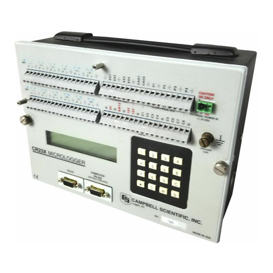
Section OV4. Working with a CR23X will help the learning process, so don't just read the examples, turn on the CR23X and do them. If you want to start this minute, go ahead and try the examples, then come back and read the rest of the Overview. - Page 12 CR23X MICROLOGGER OVERVIEW FIGURE OV1-1. CR23X Micrologger OV-2...
- Page 13 96 Storage Module, Printer, Serial Out 97 Initiate Telecommunications 120 TGT1 GOES Satellite (CS I/O only) 121 ARGOS Satellite (CS I/O only) 122 INMARSAT-C Satellite (CS I/O only) 123 TGT1 Programming FIGURE OV1-2. CR23X Panel and Associated Programming Instructions OV-3...
-
Page 14: Ov1.1 Wiring Terminals
(Section 6). An optically isolated computer The terminals labeled P1, P2, P3, and P4 are RS-232 port is also provided for direct the pulse counter inputs for the CR23X. They connection to PCs and other RS-232 devices. are programmable for high frequency pulse, low... -
Page 15: Ov1.2 Connecting Power To The Cr23X
A 6 foot 9 to 9 pin serial cable and a programs, and labels. SRAM is used for final 9 to 25 pin adapter are included with the CR23X storage data and running the user program. to connect this port to a PC serial port. - Page 16 Mode, Section 1.5). 4. Intermediate Storage - Certain Processing Instructions and most of the Output 6. Alphanumeric Labels - The CR23X can Processing Instructions maintain be programmed through EDLOG (PC208W intermediate results in Intermediate software) to assign alphanumeric labels to Storage.
-
Page 17: Operating System
Total 1152 Kbytes Total 512 Kbytes The Operating System is loaded into Flash Memory at the factory. System Operating System Memory is used while the CR23X is 32K SRAM running for calculations, buffering data (128 Kbytes) and general operating tasks. -
Page 18: Ov2.2 Program Tables, Execution Interval And Output Intervals
Subroutines, called from Tables 1 and 2, are INTERVAL AND OUTPUT INTERVALS entered in Subroutine Table 3. The size of The CR23X must be programmed before it will program memory can be fixed or automatically make any measurements. A program consists allocated by the CR23X (Section 1.5). -
Page 19: Ov2.3 Cr23X Instruction Types
2. PROCESSING INSTRUCTIONS (30-68, execution interval overrun (table overrun) Section 10) perform numerical operations occurs; the CR23X finishes processing the on values located in Input Storage and table and waits for the next execution interval store the results back in Input Storage. - Page 20 CR23X MICROLOGGER OVERVIEW INPUT/OUTPUT INSTRUCTIONS Specify the conversion of a sensor signal to a data value and store it in Input Storage. Programmable entries specify: (1) the measurement type (2) the number of channels to measure (3) the input voltage range...
-
Page 21: Ov3. Communicating With Cr23X
∗ mode as outlined in Section 5. The most useful updated for three minutes, except in the command to most CR23X users is the 7H mode, where it is left on indefinitely. The command, which places the CR23X in the display can be turned off from the keypad in the Remote Keyboard Mode. -
Page 22: Ov3.2 Using Computer With Datalogger Support Software
The SC12 Two Peripheral cable which comes with the SC32A is used to connect the CS I/O Back up to previous instruction in port of the CR23X to the 9 pin port of the program table or to previous Output SC32A labeled "Datalogger". Connect the Array in Final Storage "Terminal/Printer"... -
Page 23: Ov4. Programming The Cr23X
NOTE: The program must be executed for may be entered, including the mode in which output to occur. Therefore, the interval at programs may be keyed in to the CR23X from which the Output Flag is set must be evenly the computer/terminal. -
Page 24: Ov4.3 Entering A Program
CR23X MICROLOGGER OVERVIEW Storage locations on which to find maxima, (2) Once a program is loaded in the CR23X, the TIME, an option of storing the time of program will be stored in flash memory and will occurrence with the maximum value, and (3) -
Page 25: Ov5.1 Sample Program 1
1: Panel Temperature (P17) memory memory Loc [ CR23XTemp ] When the CR23X is turned on, it tests the FLASH 2: Do (P86) memory and loads the current program to RAM. Set Output Flag High After the program compiles successfully, the CR23X begins executing the program. - Page 26 02:P00 This is the DO instruction (a The CR23X is now programmed to read the panel Program Control temperature every 5 seconds and place the reading Instruction). in Input Storage Location 1. The program can be Enter 86 and...
-
Page 27: Ov5.2 Sample Program 2
CR23X MICROLOGGER OVERVIEW Loc [ TCTemp The CR23X is now programmed to measure Mult the internal temperature every 5 seconds and send each reading to Final Storage. Values in Offset ∗ Final Storage can be viewed using the Mode. 3: If time is (P92) -
Page 28: Ov5.3 Editing An Existing Program
TC output curve (Section 13.4). The first example described program entry one keystroke at a time. This example does not Instruction 14 directs the CR23X to make a show the "A" key. Remember, "A" is used to differential TC temperature measurement. The enter and/or advance (i.e., between each line in... - Page 29 03:10 Set Output Flag 0 The CR23X is programmed to measure the thermocouple temperature every sixty seconds. The If Time instruction sets the Output Flag at the beginning of every hour. Next, the Output Instructions for time and average are added.
- Page 30 CR23X MICROLOGGER OVERVIEW 09: P74 Minimize instruction 01:1 One repetition 02:10 Output the time of the daily minimum in hours and minutes 03:2 Data source is Input Storage Location 2. The program to make the measurements and to send the desired data to Final Storage has been entered.
-
Page 31: Ov6. Data Retrieval Options
"milked" of its data or is brought back to the They are written over by new data (Section 2.1) office/lab where the data is transferred to Memory is reallocated or the CR23X is reset the computer. In the latter case, a "fresh" (Section 1.5) - Page 32 2. THE DSP4 HEADS UP DISPLAY ALLOWS THE USER TO VIEW DATA IN INPUT STORAGE. ALSO BUFFERS FINAL STORAGE DATA AND WRITES IT TO PRINTER OR STORAGE MODULE. 3. ALL CAMPBELL SCIENTIFIC RS-232 INTERFACE PERIPHERALS HAVE A FEMALE 25 PIN RS-232 CONNECTOR. 4. THE “COMPUTER RS-232” PORT HAS A FEMALE 9 PIN CONNECTOR.
-
Page 33: Ov7. Specifications
Encased in metal with gas discharge tubes on the ACCURACY: ±0.025% of FSR; 0° to 40°C panel, the CR23X has EMI filtering and ESD protection ±0.05% of FSR; -25° to 50°C ACCURACY: ±0.02% of FSR (±0.015%, 0° to 40°C) on all input and output connections. - Page 34 CR23X MICROLOGGER OVERVIEW This is a blank page. OV-24...
-
Page 35: Functional Modes
0 is entered. seconds except when output occurs (every 10 minutes). With final output the processing time is The sample rate for a CR23X measurement is 1 second. With the execution interval set at 0.1 the rate at which the measurement instruction seconds, and a one second lag between samples can be executed (i.e., the measurement made,... - Page 36 PARAMETER ENTRY TABLE 1.1.4 interval, and locations 1 and 2 to the multiplier and offset of the measurement instruction. The CR23X mode is a table with up to Note that a default execution interval of zero one hundred values. Each value corresponds...
- Page 37 Once the EDLOG created program has been sent to the CR23X, it can be saved in the Flash the program that was downloaded does not memory program storage area using the contain any assignments.
-
Page 38: Setting And Displaying The Clock - Mode
October 12. number and the 9-character label assigned to toggles back to Day that location in the programming portion of Year. (EDLOG) of Campbell Scientific’s PC208W Time Display/enter datalogger support software. If the value stored HHMM hours:minutes... -
Page 39: Compiling And Logging Data - Mode
If D is keyed (for Flags 1 to 8), or 1 is keyed (for Flags 11 to 18) while the CR23X is displaying a NOTE: All output ports are set low, the location value, the current status of the user flags... - Page 40 SECTION 1. FUNCTIONAL MODES of memory can be displayed in the Final Storage holds stored data for a mode. A “--“ after the number displayed means permanent record. Output Instructions store that the memory test was aborted. The number data in Final Storage when the Output Flag is shown indicates how far the test progressed set (Section 3.7).
- Page 41 Total 1152 Kbytes Total 512 Kbytes The Operating System is loaded into Flash Memory at the factory. System Operating System Memory is used while the CR23X is 32K SRAM running for calculations, buffering data (128 Kbytes) and general operating tasks.
- Page 42 Changing the size of program memory results in all data being erased. Enter 0 and the CR23X will assign the exact number needed above 116. Entering 0 will also result in the CR23X erasing all data whenever the program is changed and compiled.
-
Page 43: Revision
As different versions are released, allocate for program memory COMPLETELY there may be operational differences. When RESETS THE CR23X. All memory is erased calling Campbell Scientific for datalogger including any stored programs and memory is assistance, please have these numbers checked. - Page 44 SECTION 1. FUNCTIONAL MODES TABLE 1.6-1. Description of Mode Data Keyboard Display ID: Entry Data Description of Data Program memory Signature. The value is dependent upon the +XXXXX programming entered and memory allotment. If the program has not been previously compiled, it will be compiled and run. Operating System (OS) Signature +XXXXX Memory Size, Kbytes (Flash + SRAM).
-
Page 45: Mode -- Security
Passwords are part of the program. If security hanging up, security is reset. is enabled in the active program, it is enabled as soon as the program is run when the CR23X MODE -- SAVE OR LOAD is powered up. - Page 46 Erasable Programmable Read Only Memory is non-volatile memory that can only be erased in When " D" is keyed in, the CR23X will display 16K blocks. The CR23X has 512K of Flash "13: Enter Command". A command (Table 1.8-...
- Page 47 Internal Flash Address 1 will work with any Storage Module Key entry Display address; the CR23X will search for the lowest 13: Enter Command address Storage Module that is connected. The command to save, load, or clear a program and 07: Program ID the program number (Table 1.8-5) is entered.
- Page 48 See “Telecommunications” R command information on changing default settings in each temperature range. If x=0 the CR23X is set for full duplex. If x=1 the CR23X is set for half duplex. TABLE 1.8-9. You may now change the option:...
- Page 49 SECTION 1. FUNCTIONAL MODES TABLE 1.8-10. Set Initial Baud Rate / Set TABLE 1.8-12. Set Program Compile Option RS232 Power Entry Display Comments Entry Display Comments 13:Enter Command 13:Enter Command 13: Compile Option 12: Connect Baud Rate 13: Compile Option Sets Compile 12: Connect Baud Rate Enter Baud...
- Page 50 SECTION 1. FUNCTIONAL MODES This is a blank page. 1-16...
-
Page 51: Final Storage Areas, Output Arrays, And Memory Pointers
SECTION 2. INTERNAL DATA STORAGE Final Storage Area 1 is the default storage area 2.1 FINAL STORAGE AREAS, OUTPUT and the only one used if the operator does not ARRAYS, AND MEMORY POINTERS specifically allocate memory to Area 2. Final Storage is the memory where final processed data are stored. - Page 52 Final Storage IF THE STORAGE MODULE IS CONNECTED TO THE CR23X. If the Storage Module is not connected, the CR23X does not transmit the data nor does it advance the SPTR to the new DSP location. It FIGURE 2.1-2.
-
Page 53: Data Output Format And Range Limits
Storage Area. To locate a specific Output above, the computations performed in the Array, enter a location number that positions the CR23X are done in floating point arithmetic. In Display Pointer (DPTR) behind the desired data Input and Intermediate Storage, the numbers and press the "A"... - Page 54 SECTION 2. INTERNAL DATA STORAGE the Output Array equal to or just ahead of the TABLE 2.3-1. Mode Command location entered. Whenever a location number Summary is displayed by using the "#" key, the corresponding data point can be displayed by Action pressing the "C"...
-
Page 55: Instruction Set Basics
Instructions are identified by a number. There are a fixed number of parameters associated with each instruction to give the CR23X the information required to execute the instruction. The set of instructions available in the CR23X is determined by the CR23X Operating System. -
Page 56: Voltage Range And Overrange Detection
To index an input location (4 digit integer) or set Voltages greater than 16 volts may permanently port command (2 digit integer) parameter, damage the CR23X. or "-" is pressed after keying the value but before entering the parameter. Two minus 3.6 OUTPUT PROCESSING... -
Page 57: Use Of Flags: Output And Program Control
Storage, and Flag 9 disables intermediate processing. Flags 1-8 and 11-18 may be used Each group of Output Processing Instructions as desired in programming the CR23X. Flags 0 creating an Output Array is preceded by a and 9 are automatically set low at the beginning Program Control Instruction that sets the Output of each execution of the program table. -
Page 58: Program Control Logical Constructions
SECTION 3. INSTRUCTION SET BASICS As an example, suppose it is desired to obtain a TABLE 3.8-1. Command Codes wind speed rose incorporating only wind speeds Go to end of program table greater than or equal to 4.5 m/s. The wind 1-9, 79-99 Call Subroutine 1-9, 79-99 speed rose is computed using the Histogram... -
Page 59: Instruction Memory And Execution Time
SECTION 3. INSTRUCTION SET BASICS then used to compare the value in the location with fixed values. When the value in the input location is less than the fixed value specified in Instruction 83, the command in that Instruction 83 is executed, and execution branches to the END Instruction 95 which closes the case test (see Instruction 93, Section 12). - Page 60 SECTION 3. INSTRUCTION SET BASICS...
- Page 61 SECTION 3. INSTRUCTION SET BASICS TABLE 3.9-2. Processing Instruction Memory and Execution Times R = No. of Reps. INPUT MEMORY PROG. INSTRUCTION LOC. INTER. LOC. BYTES EXECUTION TIME (ms) 30 Z=F + = 0.5 + 0.1 exponent - = 0.5 + 0.3 * exponent 31 Z=X 32 Z=Z+1 33 Z=X+Y...
- Page 62 SECTION 3. INSTRUCTION SET BASICS TABLE 3.9-3. CR23X Output Instructions R = No. of Reps. FINAL INTER. MEMORY FLAG O FLAG 0 INSTRUCTION LOC. VALUES BYTES OPTION HIGH 69 WIND VECTOR 2+9R 2.7+8.3R 3.9+38.7R 2.7+8.3R 4.5+15.6R 2.4+8.8R 3.8+34.7R 2.1+8.2R 0.0+27.3R 2.1+8.2R...
-
Page 63: Error Codes
The detected during compilation, an E is displayed with CR23X keeps track of the number of times (up the 2 digit error code. The Instruction Location to 99) that E08 has occurred. The number can... - Page 64 SECTION 3. INSTRUCTION SET BASICS Compile ELSE without IF Compile EXIT LOOP without LOOP Compile IF CASE without BEGIN CASE Compile IF and/or LOOP nested too deep Run Time SUBROUTINES nested too deep Compile Instruction 3 and interrupt subroutine use same port Editor Instruction does not exist Editor...
-
Page 65: External Storage Peripherals
External data storage devices are used to provide a data transfer medium that the user can carry from the test site to the lab and to supplement the internal storage capacity of the CR23X, allowing longer periods between visits to the site. The standard data storage peripheral for the CR23X is the Storage Module (Section 4.4). - Page 66 SECTION 4. EXTERNAL STORAGE PERIPHERALS Instruction 96 has a single parameter which If the CR23X is using a port (CS I/O or RS-232) specifies the peripheral to send output to. Table for other I/O tasks when Instruction 96 is 4.1-1 lists the output device codes.
-
Page 67: Manually Initiated Data Output - Mode
Day, Hour-Minute, and 586,568 divided by 491 = 1194 days. Therefore, Seconds in the 2nd - 4th data points. the CR23X would have to be visited every 1194 REMEMBER! You must specifically program days to retrieve data, because write-over would... -
Page 68: Storage Module
SECTION 4. EXTERNAL STORAGE PERIPHERALS the CR23X to output the date and time values. 4.4 STORAGE MODULE The Output Array ID, Day, and Time are always The Storage Module stores data in battery 4 character numbers, even when high resolution backed RAM. - Page 69 Modules, and 3) transfer of data Instead, the CR23X saves the data and from a Module that is left with the CR23X to a continues its other operations without advancing Module that is hand carried to the site for data the Storage Module Pointer (SPTR, Section 2.1).
- Page 70 Storage Module connected, enter the address Mode is used to issue commands to of the desired Storage Module. Address 1 will the SM192/716 Storage Module, from the CR23X. always work if only one Module is connected. These commands are like...
- Page 71 SECTION 4. EXTERNAL STORAGE PERIPHERALS 07:XXXXXX SM location at end of area selected. Key A to advance to first data. If another location is keyed in SM will jump to 1st start of array following that location. Review data with: Advance and display next data point Back-up one data point Display location, C to return to data...
- Page 72 SECTION 4. EXTERNAL STORAGE PERIPHERALS This is a blank page.
-
Page 73: Telecommunications Commands
Telecommunications is used to retrieve data from Final Storage directly to a computer/terminal and to program the CR23X. Any user communication with the CR23X that makes use of a computer or terminal is done through Telecommunications. - Page 74 2. All commands are of the form: [no.]letter, where the number may or may not be optional. The CR23X sends ASCII data with 8 bits, no parity, one start bit, and one stop bit. 3. Valid characters are the numbers 0-9, the...
- Page 75 [F.S. Area]A SELECT AREA/STATUS - If 1 or 2 does not precede the A to select the Final Storage Area, the CR23X will default to the Area last used (initially this is Area 1). All subsequent commands other than A will address the area selected.
- Page 76 Display/change value at Input Storage location. CR23X sends the value stored at the location. A new value and CR may then be sent. CR23X sends checksum. If no new value is sent (CR only), the location value will remain the same.
- Page 77 140:110:90:65:50:45:34:30R <crlf> The setting of the eight contrast temperature bins is initially done at Campbell Scientific. Below are the contrast settings of one type of LCD screen for temperatures from <-15 to >+50 °C. A user can also adjust the value of the current bin by entering the * D mode while in Remote Keyboard Mode.
-
Page 78: Remote Programming Of The Cr23X
Hyperterminal) and connecting via serial cable to the CR23X. PC208W’s Connect screen also The user can step back and forth between the offers such a Terminal window. The CR23X can Telecommunications Command State and the be placed in the Remote Keyboard State by Remote Keyboard State. -
Page 79: Computer Rs-232 9-Pin Description
The CS I/O interface utilizes (0 - 5) V signal levels and is to be used to connect to Campbell Scientific communications peripherals. Either 9-pin interface can be used for telecommunications, however, only one of these two interfaces can be active at once. - Page 80 SECTION 6. 9-PIN SERIAL INPUT/OUTPUT TABLE 6.2-1. Pin Description ABR = Abbreviation for the function name. PIN = Pin number. Signal Out of the CR10X to a peripheral. Signal Into the CR10X from a peripheral. PIN ABR Description 5V: Sources 5 VDC, used to power peripherals. Signal Ground: Provides a power return for pin 1 (5V), and is used as a reference for voltage levels.
- Page 81 PERIPHERALS characters on a print peripheral. While several peripherals may be connected in parallel to the CS I/O port, the CR23X has only 6.2.1.2 ADDRESSED PERIPHERALS one transmit line (pin 9) and one receive line (pin 4, Table 6.2-1). The CR23X selects a peripheral...
- Page 82 " ". simultaneously raising SDE (Figure 6.2-4). TXD must be low while SDE and CLK/HS are The ME line is held high until the CR23X receives changing to the high state. an "E" to exit telecommunications. The ME is...
- Page 83 SDs must drop the Ring line in this state. This B7 B6 B5 B4 B3 B2 B1 B0 state is not used by SDs. The CR23X must force the SDs back to the reset state from State 5 before addressing SDs.
- Page 84 The SC32A raises the CR23X's ring line when it garbage characters on a computer/terminal. receives characters from a modem, and converts the CR23X's logic levels (0 V logic low, 5V logic high) to RS-232 logic levels. 6.2.6.2 SC932 INTERFACE TO MODEMS...
- Page 85 0 to make the parity of the character telephone line. correct. The CR23X ignores the 8th bit of a character that is receives, and transmits the 8th Data Set Ready: The modem raises this line to bit as a binary 0.
- Page 86 2. Verify that the port of the modem/terminal is 76800 baud. In the Telecommunications State, an asynchronous serial communications the CR23X will set its baud rate to match the port configured as DTE (see Table 6.2-4). baud rate of the computer/terminal. Some baud...
-
Page 87: Use Of Instruction 96
Mode is used to manually initiate communication cannot be established. data transfer from Final Storage to a peripheral. An abort flag is set if any key on the CR23X or 6.3 USE OF INSTRUCTION 96 terminal is pressed during the transfer. Data... - Page 88 SECTION 6. 9-PIN SERIAL INPUT/OUTPUT This is a blank page. 6-10...
-
Page 89: Single-Ended Voltage/Switched 12 V Terminal - Cs500
SECTION 7. MEASUREMENT PROGRAMMING EXAMPLES This section gives some examples of Input Programming for common sensors used with the CR23X. These examples detail only the connections, Input, Program Control, and Processing Instructions necessary to perform measurements and store the data in engineering units in Input Storage. Output Processing Instructions are omitted. - Page 90 5000 mV Slow 60 Hz Rejection Range INPUT LOCATIONS SE Channel 1 Temp_C Loc [ RH_pct 2 RH_pct Mult Offset CR23X Temperature (Black) SE 5 Relative Humidity (Brown) SE 6 12 V (Red) CS500 SWITCHED 12V Power Ground (Green) Shield (Clear) FIGURE 7.1-1.
-
Page 91: Differential Voltage Measurement
When a number of thermocouple measurements The wire used to supply power from the external are made at some distance from the CR23X, it is battery is 18 AWG with an average resistance of often better to use a reference junction box 6.5 ohms/1000 ft. -
Page 92: Temperature Probe
CR23X 12V supply. Mult Supplemental charging, AC or solar, should be Offset used with the CR23X. If a charging source is not practical, back-up batteries should be used to 2: Thermocouple Temp (DIFF) (P14) compensate for the increased current drain. -
Page 93: Tipping Bucket Rain Gage With Long Leads
In this example, it is desired to measure a temperature in the range of -10 to 7.7 TIPPING BUCKET RAIN GAUGE C. The length of the cable from the CR23X WITH LONG LEADS to the PRT is 500 feet. -
Page 94: Ohm Prt In 3 Wire Half Bridge
50 mV, 60 Hz Reject, Slow, If the actual resistances were the nominal Br Range values, the CR23X would not overrange with V DIFF Channel = 4.4V. To allow for the tolerances in the actual Excite all reps w/Exchan 1 resistances, it is decided to set V equal to 4.2... -
Page 95: Ohm Prt In 4 Wire Full Bridge
Instruction 16 from the measured ratio would be about 0.1 C lower CR23X than the actual temperature of the PRT. This source of error does not exist in the example in Section 7.8, where a 4 wire half bridge is used to measure PRT resistance. -
Page 96: Pressure Transducer - 4 Wire Full Bridge
±0.01% accuracy tolerance would hold over the The sensor is calibrated by connecting it to the desired temperature range. CR23X and using Instruction 6 with a multiplier of 1 and an offset of 0, noting the readings The relationship between temperature and PRT Mode) with 10 cm of water above the resistance is a slightly nonlinear one. -
Page 97: Lysimeter - 6 Wire Full Bridge
There is 1000 feet of 22 AWG cable between 7.48 Offset the CR23X and the load cell. The output of the load cell is directly proportional to the excitation 7.12 LYSIMETER - 6 WIRE FULL voltage. When Instruction 6 (4 wire half bridge) - Page 98 C change in temperature. Assume that content of the soil in the lysimeter is the cable between the load cell and the CR23X approximately 25% on a volume basis. It is lays on the soil surface and undergoes a 25 decided to use this as the reference, (i.e., 0.25 x...
-
Page 99: Gypsum Soil Moisture Block
Reps Instruction 59, Bridge Transform. 1000 mV, Fast Range SE Channel The Campbell Scientific 227 Soil Moisture Block Excite all reps w/Exchan 1 uses a Delmhorst gypsum block with a 1 kohm 1000 mV Excitation... - Page 100 FIGURE 7.14-1. 101 Thermistor Probes appropriate polynomial fit has been determined. Connected to CR23X In this example, the CR23X is used to measure the temperature of 5 Campbell Scientific 101 PROGRAM Probes (used with the CR21). Instruction 4,...
-
Page 101: Water Level - Geokon'svibrating Wire Pressure Sensor
Figure 7.15-1 illustrates how an "pickup" coils and inducing the same frequency increase in pressure on the diaphragm on the lines to the CR23X. Instruction 28 then decreases the tension on the wire attached to accurately measures how much time it takes to the diaphragm. - Page 102 SECTION 7. MEASUREMENT PROGRAMMING EXAMPLES The following calculations are based on using a the well to the water surface. The sensor is Geokon model 4500 Vibrating Wire sensor. An vented to atmosphere to eliminate individual multiplier and offset must be measurement errors due to changes in calculated for each sensor used in a system.
- Page 103 SECTION 7. MEASUREMENT PROGRAMMING EXAMPLES CR23X & AVW1 FIGURE 7.15-2. Well Monitoring Example 7-15...
- Page 104 CR23X FIGURE 7.15-3. Hook up to AVW1 Polynomial (P55) PROGRAM Reps X Loc [ Temp AVW1 & CR23X USED TO MEASURE 1 F(X) Loc [ Temp GEOKON VIBRATING WIRE SENSOR. 4: -104.78 5: 378.11 * Table 1 Program 6: -611.59 Execution Interval (seconds) 7: 544.27...
-
Page 105: Paroscientific "T" Series Pressure Transducer
The pressure output requires temperature AC voltage; must be centered around compensation. Instruction 27 measures the CR23X ground. outputs and returns period in microseconds (refer to Table 7.16-1). 7-17... - Page 106 U + T CONNECTIONS Tau= measured period, in microseconds, of Figure 7.16-1 details the components required pressure for connecting the transducer to the CR23X. The user supplied components are commonly = measured period, in microseconds, of available at commercial electronic stores. temperature...
- Page 107 SECTION 7. MEASUREMENT PROGRAMMING EXAMPLES CR23X CONNECTIONS FIGURE 7.16-1. CR23X/Paroscientific "T" Series Transducer Wiring Diagram PROGRAM EXAMPLE IF (X<=>F) (P89) X Loc [ Comp_Chk ] The following example reads the coefficients from a subroutine only when the datalogger program is compiled. The coefficients are Call Subroutine 1 stored in Input Locations 3 through 16.
-
Page 108: To 20 Ma Sensor Using Curs100 Terminal Input Module
The dew point sensor is measured with a 21.801 differential voltage measurement on differential analog input 4. The CURS100 TIM and dew point sensor are wired to the CR23X wiring panel as shown in Figure 7.17-1. Loc [ D2 PROGRAM... - Page 109 SECTION 7. MEASUREMENT PROGRAMMING EXAMPLES CR23X CR10X 4 to 20 mA 0.01% Sensor CURS100 12V Power Out FIGURE 7.17-1 Wiring Diagram for CURS100 Terminal Input Module and 4 to 20 mA Sensor. 7-21...
- Page 110 SECTION 7. MEASUREMENT PROGRAMMING EXAMPLES This is a blank page. 7-22...
-
Page 111: Processing And Program Control Examples
SECTION 8. PROCESSING AND PROGRAM CONTROL EXAMPLES The following examples are intended to illustrate the use of Processing and Program Control Instructions, flags, dual Final Storage, and the capability to direct the results of Output Processing Instructions to Input Storage. The specific examples may not be as important as some of the techniques employed, for example: Directing Output Processing to Input Storage is used in the Running Average and Rainfall Intensity examples (8.1 and 8.2). -
Page 112: Rainfall Intensity
SECTION 8. PROCESSING AND PROGRAM CONTROL EXAMPLES Sample (P70) Set Active Storage Area (P80) Reps Input Storage Area Loc [ 10smpl_mx ] Array ID or Loc [ max_i INPUT LOCATIONS Maximum (P73) Reps Loc [ XX_mg_M3 ] 1 Panl_Temp 15 Temp_i_5 2 10smpl_mx 16 Temp_i_4 Spatial Maximum (P49) -
Page 113: Using Control Ports And Loop To Run Am416 Multiplexer
Array ID or Loc [ 15min_tot ] Measure the 107 probe located at the AM416 for TC temperature reference. Totalize (P72) CR23X sets the port high which resets the Reps AM416. Loc [ Precip_mm ] A loop is entered; within each pass: IF (X<=>F) (P89) - Page 114 SECTION 8. PROCESSING AND PROGRAM CONTROL EXAMPLES CR23X AM416 FIGURE 8.3-1. AM416 Wiring Diagram For Thermocouple and Soil Moisture Block Measurements PROGRAM Ref Temp Loc [ Ref_Temp ] Table 1 Program Loc [ TC_#1 Mult 600.0 Execution Interval (seconds) Offset...
-
Page 115: Sub 1 Minute Output Interval Synched To Real Time
If the table connected as diagrammed below. overran its execution interval (Section 1.1.1), the output interval would not be the count CR23X multiplied by the execution interval, but some longer interval. In this example a temperature (107 Temperature Probe) is measured every 0.5... -
Page 116: Sdm-Ao4 Analog Output Multiplexer To Strip Chart
Volts (SE) (P1) on weather data. The SDM-A04 may be used Reps with the CR23X to provide an additional four ±10 mV Slow Range analog outputs to strip charts. The output SE Channel values in this example are wind speed, wind Loc [ Rs direction, air temperature, and solar radiation. -
Page 117: Converting 0-360 Wind Direction Output To 0-540 For Strip Chart
0-360 Reps degree input to 0-540. (If you have a 0-540 pot, Address it can be used with the CR23X since the Wind Loc [ WS_out Vector Instruction, 69, will work with this output.) If time is (P92) -
Page 118: Use Of 2 Final Storage Areas - Saving Data Prior To Event
SECTION 8. PROCESSING AND PROGRAM CONTROL EXAMPLES Z=X (P31) Area 2. Thus, Area 2 holds 21 seconds (4 X Loc [ 0_360_WD ] values/second x 21 seconds = 84 locations). 2: 10 Z Loc [ 0_540_WD ] When 25 pounds is exceeded, 10 is loaded into IF (X<=>F) (P89) an input location and flag 1 is set high. -
Page 119: Logarithmic Sampling Using Loops
SECTION 8. PROCESSING AND PROGRAM CONTROL EXAMPLES If Flag/Port (P91) 8.9 LOGARITHMIC SAMPLING USING Do if Flag 1 is Low LOOPS Then Do A ground water pump test requires that water Do (P86) level be measured and recorded according to Set Flag 1 High the following schedule. - Page 120 SECTION 8. PROCESSING AND PROGRAM CONTROL EXAMPLES Beginning of Loop (P87) PROGRAM Delay Table 1 Program Loop Count Execution Interval (seconds) Do (P86) ;User must toggle Flag 1 to start measurements. Call Subroutine 1 If Flag/Port (P91) End (P95) Do if Flag 1 is Low Go to end of Program Table ;Loop 6, Output every 10 minutes until stopped by user.
-
Page 121: Covariance Correlation Programming Example
The vertical wind prop calibration differs the Input Storage locations for the processed results. from the U and V prop calibration. The fastest TABLE 8.10-1. Example Sensor Description and CR23X Multiplier and Offset DESCRIPTION SYMBOL SENSOR... - Page 122 SECTION 8. PROCESSING AND PROGRAM CONTROL EXAMPLES Table 8.10-3 lists the input channel bulb measurements to vapor pressure using configuration and Input Storage allocation for Instruction 57 requires atmospheric pressure. the measured values. After reading the new We'll use the standard atmosphere for the site input samples, the Level 2 measurements are elevation and key the value into Location 17 relocated using the Block Move Instruction 54,...
- Page 123 SECTION 8. PROCESSING AND PROGRAM CONTROL EXAMPLES AM25TMultiplexer (P134) Reps 10 mV, Fast Range Channel DIFF Channel Exchan 1, 60 Hz Reject Clock Control Reset Control Type E (Chromel-Constantan) Ref Temp (Deg. C) Loc [ Ref_Temp ] Loc [ Ta2_1 Mult Offset Z=X*F (P37)
- Page 124 SECTION 8. PROCESSING AND PROGRAM CONTROL EXAMPLES Covariance/Correlation (P62) No. of Input Locations No. of Means No. of Variances No. of Std. Dev. No. of Covariance No. of Correlations Samples per Average First Sample Loc [ W1 Loc [ MEAN_W1 ] Covariance/Correlation (P62) No.
-
Page 125: Fast Fourier Transform Examples
8.11.1. EXAMPLE WITHOUT BIN AVERAGING signal at the beginning of the first interval and the end of the last interval can be determined by The CR23X was used to generate data looking at the CR23X program that generated representing two superimposed sine wave signals, one at 1.25 Hz (amplitude = 1) and the other at... - Page 126 SECTION 8. PROCESSING AND PROGRAM CONTROL EXAMPLES FIGURE 8.11-2. FFT Power Spectra Analysis of 0.25 and 1.25 Hz Signal TABLE 8.11-1. FFT Real and Imaginary Results 0.25 and 1.25 Hz Signal BIN # FFT Ri FFT Ii 0.02303 0.009766 0.01036 0.019532 -0.00206 0.029298...
- Page 127 SECTION 8. PROCESSING AND PROGRAM CONTROL EXAMPLES TABLE 8.11-2. FFT Magnitude and Phase Results 0.25 and 1.25 Hz Signal BIN # FFT Mi FFT Pi 0.02303 0.009766 0.01036 0.019532 0.00206 0.029298 -99999 0.214852 0.00086 185.58 0.224618 0.01154 17.952 0.234384 0.20321 197.78 0.24415 0.62935...
- Page 128 Intermediate Locations 1028 Y Loc [ _________ ] Z Loc [ #1 8.11.2 EXAMPLE WITH BIN AVERAGING The CR23X was used to generate data Z=X+F (P34) simulating wave data from an ocean buoy with 1025 X Loc [ _________ ] four superimposed sine wave signals, 0.1,...
- Page 129 SECTION 8. PROCESSING AND PROGRAM CONTROL EXAMPLES FIGURE 8.11-3. Simulated Ocean Buoy Wave Data FIGURE 8.11-4. Simulated Ocean Buoy FFT Results 8-19...
- Page 130 SECTION 8. PROCESSING AND PROGRAM CONTROL EXAMPLES TABLE 8.11-4. FFT Bin Averaging Results from Simulated Ocean Buoy Wave Data BIN # FREQUENCY FFT*0.1 BIN # FREQUENCY FFT*0.1 0.00195 0.0507 0.0039 0.05265 0.00585 0.0546 0.0078 0.05655 0.00975 0.0585 0.0117 0.06045 0.01365 0.0624 0.0156 0.06435...
- Page 131 SECTION 8. PROCESSING AND PROGRAM CONTROL EXAMPLES If Flag/Port (P91) Z=FRAC(X) (P44) Do if Flag 2 is High X Loc [ #1 Then Do Z Loc [ #1 FFT (P60) Z=X+F (P34) Log (base 2) of Samples X Loc [ #1 Power Spectra/Taper Log (base 2) of Bins Z Loc [ _________ ]...
-
Page 132: Using The Switched 12 V To Power Sensors
X Loc [ _________ ] Y Loc [ _________ ] The Switched 12 V terminal on the CR23X Z Loc [ _________ ] wiring panel is used to power the ASPTCs. The maximum amount of current that the Switched End (P95) 12 V terminal can source is 600 mA at 50°C... - Page 133 ASPTC (UPPER) BLACK SWITCHED 12 V BLACK FIGURE 8.12-1. Connections to Power Two 12 V ASPTCs with the Switched 12 V on the CR23X Wiring Panel PROGRAM Table 1 Program Do (P86) Execution Interval (seconds) Set Port 9 Low Z=X-Y (P35)
- Page 134 SECTION 8. PROCESSING AND PROGRAM CONTROL EXAMPLES This is a blank page. 8-24...
- Page 135 NOTE: When a voltage input exceeds the range programmed, the value which is stored is set to the maximum negative number and displayed as -99999 in high resolution or -6999 in low resolution. *** 1 SINGLE-ENDED VOLTS *** inputs must be within ±5.0 V of the CR23X's ground (see Common Mode Range in Section FUNCTION 14.7.2).
- Page 136 Lower Threshold: 1.5 V Upper Threshold: 3.5 V The use of control ports for pulse measurement causes the CR23X to use a continuous 10 mA *Larger input transitions are required at high of power. frequencies because of the input RC filter with 1.2 microsecond time constant.
- Page 137 As counter reset frequency increases, at 5 V. The count is incremented when quiescent current drain of the CR23X increases. the switch closes. If power consumption is less of a concern, parameter 3 of the Pulse Counter (P3) instruction can be indexed (e.g.
- Page 138 Counts on Control Ports C5..C8 are measured by a coprocessor. The coprocessor transfers Using ports C5..C8 to count pulses increases the quiescent current of the CR23X by 8 mA. counts into 16 bit accumulators. The Maximum input frequency on ports C5..C8 is accumulators accumulate up to 65,535 counts.
- Page 139 SECTION 9. INPUT/OUTPUT INSTRUCTIONS less than 4 seconds, control ports C5..C8 PARAM. DATA measure frequency much more precisely than NUMBER TYPE DESCRIPTION do pulse channels. Repetitions Pulse channel or Pulse Channels Control Port number for Hz = counts / Execution Interval first measurement Maximum Error (Hz) = [1/(Execution Configuration code...
- Page 140 SECTION 9. INPUT/OUTPUT INSTRUCTIONS *** 5 AC HALF BRIDGE *** number (1X) causes the channel to be incremented with each repetition. FUNCTION This instruction is used to apply an excitation PARAM. DATA NUMBER TYPE DESCRIPTION voltage to a half bridge (Figure 13.5-1), make a single-ended voltage measurement of the Repetitions bridge output, reverse the excitation voltage,...
- Page 141 SECTION 9. INPUT/OUTPUT INSTRUCTIONS PARAM. DATA PARAM. DATA NUMBER TYPE DESCRIPTION NUMBER TYPE DESCRIPTION Repetitions Repetitions Range code for both Range code (Table 9-1) measurements (Table Differential channel 9-1) number for first Single-ended channel measurement number for first Excitation channel number measurement (Table 9-2A) Excitation channel...
- Page 142 *** 10 BATTERY VOLTAGE *** Single-ended channel number of first FUNCTION measurement This instruction measures the CR23X input Excitation channel/ voltage and writes it to an input location. The Integration (Table 9-3) units for voltage are volts. The measurement is Input location for first .2 to .3 volts less than actual battery voltage...
- Page 143 SECTION 9. INPUT/OUTPUT INSTRUCTIONS Input location for first NOTE: The temperature value used in R.H. measurement compensating the RH value (Parameter 5) Multiplier must be obtained (see Instruction 11) prior Offset to executing Instruction 12 and must be in Celsius. Input locations altered: 1 per repetition *** 13 THERMOCOUPLE TEMPERATURE, *** The RH results are placed sequentially into the...
- Page 144 Table 9-4 gives the thermocouple type codes becomes an input for Parameter 4. Enter a 9 in front of the code location containing and the CR23X will make a check on common voltage measurement) mode range; -99999 is output for temperature if Thermocouple type common mode range is exceeded.
- Page 145 This instruction measures the temperature (°C) (SRAM) into an input location. The signature is of a thermistor that resides under the CR23X a result of the CR23X PROM, the size of wiring panel. This temperature is generally SRAM, and the entries in the...
- Page 146 C4, C3, C2, C1 option default to input configuration (i.e., they are not codes driven high or low by the CR23X, and can be used to read the status of an external signal Input locations altered: 0 using Instruction 25). When a port is set high,...
- Page 147 Digital Control Port #1. instruction or grouped around a specified trigger Option 2 is useful when 2 or more CR23X's are condition. The results of the measurements may required to start "Bursting" at the same time.
- Page 148 1000 (e.g., 0.001 represents 1 measurement). when triggering on the rising edge, if the input If 0 is entered for Parameter 6, the CR23X will starts out high, it must go low and then high continue to send data until the Instruction is again to trigger.
- Page 149 SECTION 9. INPUT/OUTPUT INSTRUCTIONS CR23X program execution will pause until the NOTE: When the raw serial data option is Telecommunication mode is exited. During this selected, the calibration values are for pause telecommunications (i.e., view input conversion to millivolts only. Parameters 11 locations in the Monitor Mode, etc.) can...
- Page 150 See Section 13.7 for help on when to use Instruction 24. NOTE: Voltages in excess of 16 volts applied to a control port can cause the PARAM. DATA CR23X to malfunction. NUMBER TYPE DESCRIPTION PARAM. DATA Option (0 for most NUM.
- Page 151 SECTION 9. INPUT/OUTPUT INSTRUCTIONS Input locations altered: 1 *** 26 TIMER *** (0 if timer is being reset) FUNCTION This instruction will reset a timer or store the *** 27 PERIOD AVERAGE (SE) *** elapsed time registered by the timer in seconds in an Input Storage location.
- Page 152 SECTION 9. INPUT/OUTPUT INSTRUCTIONS 1µF To single - ended input Sensor with Silicon diodes such as 1N4001 offset Figure 9-2. Recommended input conditioning circuit for period averaging. An internal gain stage is used to amplify low- applied input signal. This attenuation sets a level ac signals prior to a zero-crossing detector lower limit on low-frequency operation and the for the period averaging measurement.
- Page 153 SECTION 9. INPUT/OUTPUT INSTRUCTIONS # Cycles to measure a single excitation channel and measures the Time out (0.01 sec, at sensor’s output on two consecutive differential least the maximum analog input channels. The pressure and duration of the number sensor temperature are written into two of cycles specified + 1 consecutive input locations starting at the 1/2 cycles.)
- Page 154 The SW8A is addressed by the datalogger, 8,7,6,5 allowing multiple SW8A's to be connected to **Function; channels one datalogger. 16 addresses are available, 4,3,2,1 but for most applications Campbell Scientific ***Averaging option recommends no more than 4 SW8A's be connected to one datalogger. Mult Offset...
- Page 155 SECTION 9. INPUT/OUTPUT INSTRUCTIONS indicates bad RAM. Function Option 3 is not PARAM. DATA used routinely, but is helpful in "debugging". NUMBER TYPE DESCRIPTION Only one Rep is required for Option 3. Reps (# of outputs) Parameter 4 specifies the first SW8A channel to Starting Address, Base 4 be read (1..8).
- Page 156 CR23X will check the elapsed time. If the entering the decimal equivalent for the elapsed time is equal to or greater than that appropriate ASCII character (see Appendix E). given by the sensor, the CR23X will get the data from the SDI-12 sensor. In the following 9-22...
- Page 157 CR23X cannot be automatically sent in addition to the information used to view text data. listed in Instruction(s) 68. The CR23X keeps no data from the sensor response. †In addition to the Standard SDI-12 commands, the CR23X can issue ‘Extended’ SDI-12 Example: To send the command 1A0+2.3456-...
- Page 158 PARAMETER 3. PORT *** 106 SDI-12 SENSOR *** Enter the CR23X control port (C5-C8) Instruction 106 allows a CR23X to be used as connected to the SDI-12 sensor data line. The an SDI-12 sensor. The CR23X can make default port is C8.
- Page 159 *A window 2, if keying program steps in by hand. PARAMETER 1. ADDRESS Results of Instruction 106 Enter the address for the CR23X acting as an The sensor CR23X will return a set of input SDI-12 sensor (0-9, †10-126 decimal value for locations in response to the M or M1..M9...
- Page 160 *** 114 SET TIME *** PARAM. DATA NUMBER TYPE DESCRIPTION FUNCTION Instruction 114 can be used to set the CR23X UDG01 SDM address clock from values in input locations. (Base 4) Input location number PARAM. DATA for the air temperature...
- Page 161 *** 118 SDM-CAN *** normally provided for each repetition. As an option, a single excitation can be made prior to Consult Campbell Scientific. all repetitions of the measurement. A AVW1 or AVW4 Vibrating Wire Interface is required for *** 130 STATUS MONITOR ***...
- Page 162 SECTION 9. INPUT/OUTPUT INSTRUCTIONS instruction in the datalogger program will change TABLE 9-10. Extended Vibrating Wire all applicable default settling times. Multiple Range Codes P132 instructions in a datalogger program will Range Peak to Peak Volts Maximum cause settling time changes for the analog Code Required @ Max.
- Page 163 SECTION 9. INPUT/OUTPUT INSTRUCTIONS PARAM. DATA Clock Control Port NUMBER TYPE DESCRIPTION Reset Control Port Thermocouple Type (x) Option / CAO Channel (Table 9-4) Number mV result Input Location number x=1..8 Type of analog output TEKJBRSN magnitude (mV) Common Mode Range Check Input location read: 1 (See P14)
- Page 164 SECTION 9. INPUT/OUTPUT INSTRUCTIONS This is a blankpage. 9-30...
- Page 165 SECTION 10. PROCESSING INSTRUCTIONS To facilitate cross referencing, parameter PARAM. DATA descriptions are keyed [ ] to the values given on NUMBER TYPE DESCRIPTION the PROMPT SHEET. These values are Destination input defined as follows: location [Z] = Destination input location for result Input locations altered: [X] = Input location of X [Y] = Input location of Y...
- Page 166 Dest. input for EXP(X) FUNCTION Divide X by Y and place the result in an input location. Division by 0 will cause the result to be Input locations altered: set to the maximum CR23X number (99999). *** 42 1/X *** PARAM. DATA NUMBER...
- Page 167 SECTION 10. PROCESSING INSTRUCTIONS PARAM. DATA *** 43 ABS(X) *** NUMBER TYPE DESCRIPTION FUNCTION Input location of X Take the absolute (ABS) value of X and place Fixed divisor the result in an input location. Dest. input loc. For X PARAM.
- Page 168 SECTION 10. PROCESSING INSTRUCTIONS Parameter 3 cannot be entered as an indexed PARAM. DATA NUMBER TYPE DESCRIPTION location within a loop (Instruction 87). To use Instruction 49 within a loop, enter Parameter 3 4(--)* Swath [SWATH] as a fixed location and follow 49 with the Starting input location Instruction 31 (Move Data).
- Page 169 *** 55 5TH ORDER POLYNOMIAL *** where X is the SVPW derived by Instruction 56. FUNCTION This relationship was derived by Campbell Evaluate a 5th order polynomial of the form Scientific from the equations for the SVPW and the SVPI given in Lowe's paper.
- Page 170 R which is equivalent to bulb temp. [X/(1-X)], where X is the value derived by the [WB TEMP.] standard CR23X Bridge Measurement Instructions (with appropriate multiplier and Destination input offset, Section 13.5) and R represents the location for vapor MULTIPLIER value.
- Page 171 SECTION 10. PROCESSING INSTRUCTIONS *** 60 FAST FOURIER TRANSFORM *** FFT Option 0X = Power Spectrum 1X = Real & Imaginary THEORY 2X = Magnitude & Phase Instruction 60 performs a Fast Fourier X0 = No Taper Transform (FFT) on a set of data contained in X1 = Taper contiguous locations in Input Storage.
- Page 172 Power January 1978. When the taper is used, the Spectrum, Real and Imaginary, or Magnitude CR23X applies a correction by multiplying the and Phase. The rest of this section deals with results by the ratio of the variance before the the DC component, bin frequency, and the FFT taper to the variance after the taper.
- Page 173 To calculate the magnitude and phase the CR23X's FFT algorithm must first compute the FFT RESULTS WITH BIN AVERAGING real and imaginary components. Conversion...
- Page 174 SECTION 10. PROCESSING INSTRUCTIONS BIN FREQUENCY POWER SPECTRUM The band width or the frequency covered by The result of the FFT with A bins averaged, are each averaged bin is equal to FA/N where F is (N/2A)-1 bins of average spectral energy (APSn) the sample frequency in Hz (1/scan interval in representing frequencies from 0 Hz to 1/2 the seconds) and A is the number of bins being...
- Page 175 Number of correlations The instruction does not conform to the CR23X's desired four instruction types. Data located in Input Number of input Storage is processed, and the results returned to...
- Page 176 SECTION 10. PROCESSING INSTRUCTIONS TABLE 10-2. Maximum Number of Outputs and Output Order for K Input Values. (The output order flows from left to right and from top to bottom) INPUTS: ..MAX NO. OUTPUTS TYPE OUTPUTS (1st) (2nd) (3rd) (4th) (Kth) Means...
- Page 177 Parameter 9. The Sample 1. The square root algorithm in the Instruction 70 must be used to transfer the data CR23X returns a result of 0 for to Final Storage. All but the last averaging negative arguments.
- Page 178 /Tau ) * (1 - (D * (1 - T /Tau C * (1 - T In many situations, the CR23X must perform Temperature ( C) = measurement and processing tasks in addition U + Y to those associated with the COV/CORR...
- Page 179 0.2 C over the same temperature range. input storage locations. The ninth is the input location for the first data value; subsequent data Coefficients are entered using CR23X Instruction 30 values are placed in sequential input locations. (Z=F) or Instruction 65 (Bulk Load). A calibration sheet from Paroscientific lists the 14 coefficients.
- Page 180 SECTION 10. PROCESSING INSTRUCTIONS PARAM. DATA *** 66 ARCTAN *** NUMBER TYPE DESCRIPTION FUNCTION Input location of X Calculate the angle in degrees whose tangent is Input location of Y X/Y. The polarity of X and Y must be known to Destination input determine the quadrant of the angle, as shown location for...
- Page 181 SECTION 11. OUTPUT PROCESSING INSTRUCTIONS Standard deviation of horizontal wind *** 69 WIND VECTOR *** fluctuations from sub-intervals is calculated as follows: FUNCTION Instruction 69 processes the primary variables of wind speed and direction from either polar ( )=[(( ...+( )/M] (wind speed and direction) or orthogonal (fixed East and North propellers) sensors.
- Page 182 Resultant mean wind direction, u. Standard deviation of wind direction, ( u). Ue=( S Un=( S This standard deviation is calculated using Campbell Scientific's wind speed weighted or, in the case of orthogonal sensors: algorithm. Ue=( Ue Use of the Resultant mean horizontal wind...
- Page 183 SECTION 11. OUTPUT PROCESSING INSTRUCTIONS *** 71 AVERAGE *** *** 74 MINIMUM *** FUNCTION FUNCTION This instruction stores the average value over Operating in the same manner as Program 73, the given output interval for each input location this instruction is used for storing the MINIMUM specified.
- Page 184 SECTION 11. OUTPUT PROCESSING INSTRUCTIONS while the bin select value was within a particular PARAM. DATA sub-range, the value output to Final Storage NUMBER TYPE DESCRIPTION must be divided by the fraction of time that the Repetitions bin select value was within that particular sub- range (i.e., a standard histogram of the bin Number of bins select value must also be output).
- Page 185 SECTION 11. OUTPUT PROCESSING INSTRUCTIONS PARAM. DATA Code Result NUMBER TYPE DESCRIPTION xxx1 SECONDS (with resolution of 0.125 sec.) Repetitions (number of xx1x HOUR-MINUTE sequential locations to xx2x HOUR-MINUTE, 2400 instead of 0000 sample) x1xx JULIAN DAY x2xx JULIAN DAY, previous day during first Starting input location no.
- Page 186 SECTION 11. OUTPUT PROCESSING INSTRUCTIONS the burst mode. The Rainflow Instruction can . . . process either a swath of data following the . . . burst mode, or it can process "on line" similar to other processing instructions..The output is a two dimensional Rainflow Histogram for each sensor or repetition.
- Page 187 SECTION 11. OUTPUT PROCESSING INSTRUCTIONS Option (AB) Form 0 = closed, 1 = open form Output 0 = fraction, 1 = counts Input location to start storing histogram. Enter 0 to send output directly to Final Storage. Execution time: 6.5 - 7.0 ms, with 60 Amplitude Bins and one Mean Bin.
- Page 188 SECTION 11. OUTPUT PROCESSING INSTRUCTIONS This is a blankp age. 11-8...
- Page 189 SECTION 12. PROGRAM CONTROL INSTRUCTIONS *** 85 LABEL SUBROUTINE *** TABLE 12-1. Flag Description Flag 0 Output Flag FUNCTION Flag 1 to 8 User Flags This instruction marks the start of a subroutine. Flag 11 to 18 User Flags Subroutines are a series of instructions Flag 9 Intermediate Processing beginning with Instruction 85 and terminated...
- Page 190 When the loop is first entered, one pass through NOTE: If Control Ports 5, 6, 7, or 8 are the loop is made, then the CR23X delays until used for pulse measurements or interrupt the next execution interval and makes the subroutines, the CR23X will go into a 10 second pass through the loop.
- Page 191 The actual keyboard entries for the examples that they are within. The maximum nesting are shown below with the first example level in the CR23X is 11 deep. This applies to If Instruction location equal to 10. The Input Then/Else comparisons and Loops or any Instructions to make the pressure and combination thereof.
- Page 192 SECTION 12. PROGRAM CONTROL INSTRUCTIONS seconds; the rest of the time one minute 2: Time (P18) between samples is sufficient. The execution Hours into current year interval is set to 10 seconds; when a one minute {maximum 8784) sample rate is desired, a delay of 6 (6 x 10s = Mod/By 60s) is used in the loop.
- Page 193 SECTION 12. PROGRAM CONTROL INSTRUCTIONS location parameters in subsequent instructions. result is 0, the interval is up. Thus, the first interval For example, if 4 is specified, the index counter of the day always starts at midnight (0 minutes). will count up by 4 (0,4,8,12,...) inside the loop. The maximum interval is 1440 minutes.
- Page 194 Instruction 94 has no parameters. assumes Final Storage Area 1. *** 95 END *** If the CR23X is already communicating on a 9- pin serial port when Instruction 96 is executed, FUNCTION the output request is put in a queue and Instruction 95 is used to indicate the end/return program execution continues.
- Page 195 9600 76800 Theory of Operation 2400 4800 When the CR23X executes P97, it looks to see 19200 if the interrupt disable flag is low. The interrupt 38400 disable flag is one of User Flags 1-8 dedicated in P97 for this use. If the interrupt disable flag is...
- Page 196 SECTION 12. PROGRAM CONTROL INSTRUCTIONS can be output to CR23X final storage. Doing so Parameter 3 Time Limit on Call Attempt will help evaluate the success of P97. One second units. A call attempt is timed from P97 should not be placed in a conditional...
- Page 197 SECTION 12. PROGRAM CONTROL INSTRUCTIONS Additional Programming Requirements Table 12-7. Option Codes for P97 Initiate Telecommunications Radio, telephone, and generic modem applications require the use of one or more Code Device Baud Instruction P68 immediately following P97. RF95 P68 Hints: RF95 1200 RF95...
- Page 198 FLASH into RAM. The program in tries RAM is replaced by the Flash program specified ID to send in Parameter 1. If Parameter 1 is indexed, the CR23X will compile the program like the mode. Use this instruction with caution. 12-10...
- Page 199 FUNCTION This instruction is used to transmit data from Program Memory bytes = 18 CR23X Final Storage via a GOES satellite to a central ground station. See the TGT1 manual for information on Instruction 120. Input Locations Read = 0-8 depending on number of parameters using the XXX -- option.
- Page 200 SECTION 12. PROGRAM CONTROL INSTRUCTIONS space, 132 skips 2 spaces, etc. It Special Movement codes possible to use does not write over any characters written in the spaces it skips. 8, 129 Backspace 192-215 Move to the first Character on the Clears bottom line Bottom Line &...
-
Page 201: Cr23X Measurements
SECTION 13. CR23X MEASUREMENTS NOTE: Highlighted portions of this section have not been updated for the CR23X. power. This is the preferred method of AC 13.1 FAST AND SLOW MEASUREMENT rejection. SEQUENCE The CR23X makes voltage measurements by The CR23X also has options for faster AC line integrating the input signal for a fixed time and rejection. - Page 202 CR23X key pad. CR23X will result in an error in the measurement. For example, if the measuring 13.2 SINGLE-ENDED AND junction of a copper-constantan thermocouple,...
- Page 203 Another instance where a ground potential good ground connection exists through the AC difference creates a problem is in a case such wiring. If a CR23X is used to measure the as described in Section 7.2, where external output from a laboratory instrument (both...
- Page 204 (explained the input settling time constant gets too large below). The CR23X allows a 450 µs settling and to discuss procedures whereby the effects time before initiating the measurement. In most...
- Page 205 If the input settling time constant, , is known, a quick estimation of the settling error as a percentage of the maximum error (V CR23X FIGURE 13.3-2. Typical Resistive Half Bridge CR23X HI OR LO INPUT FIGURE 13.3-3. Source Resistance Model for Half Bridge Connected to the CR23X 13-5...
- Page 206 <<R [13.3-9] 6 of Table 13.3-2. /2, R [13.3-10] >>R [13.3-11] FIGURE 13.3-4. Wire Manufacturers Capacitance Specifications, C TABLE 13.3-2. Properties of Lead Wires Used by Campbell Scientific Part # Conductors Insulation (ohms/1000ft.) (pfd/ft.) 9721 3 shld. 3 pair polypropylene 9661 1 shld.
- Page 207 C were between the signal lead and shield. Campbell Scientific uses only ground as represented below. polyethylene and polypropylene insulated FIGURE 13.3-5. Model 034A Wind Direction Sensor FIGURE 13.3-6. Resistive Half Bridge Connected to Single-Ended CR23X Input 13-7...
- Page 208 Campbell Scientific's Model 107 Temperature Probe, connected to = 3.3nfd the CR23X. The lead wire is a single-shielded pair, used for conducting the excitation (V ) and = 41 pfd/ft., p/n 9721 wire signal (V ) voltages.
- Page 209 0.1-1 5-45 1000 9661 5000 034A 9721 1-222 5000 5000 0-90 Estimated time constants are for 1000 foot lead lengths and include 3.3nfd CR23X input capacitance. ** Measured peak transients for 1000 foot lead lengths at corresponding excitation, V 13-9...
- Page 210 SECTION 13. CR23X MEASUREMENTS TABLE 13.3-6. Maximum Lead Length vs. Error for Campbell Scientific Resistive Sensors Sensor Maximum Model # Error Range (µV) Length(ft.) 0.05 C 0 C to 40 C 1000 034A 3° @ 360 2083 2000 10 kohm...
- Page 211 SECTION 13. CR23X MEASUREMENTS 5. Use the CR23X to measure the input voltage is proportional to R ), but settling error associated with a given when the pigtails are extended, the signal is configuration. For example, assume long proportional to (R )/(R ).
- Page 212 SECTION 13. CR23X MEASUREMENTS FIGURE 13.3-7. Half Bridge Configuration for YSI #44032 Thermistor Connected to CR23X Showing: A) large source resistance, B) large source resistance at point P, and C) configuration optimized for input settling 13-12...
- Page 213 SECTION 13. CR23X MEASUREMENTS CR23X FIGURE 13.3-8. Measuring Input Settling Error with the CR23X CR23X FIGURE 13.3-9. Incorrect Lead Wire Extension on Model 107 Temperature Sensor CR23X FIGURE 13.3-8. Measuring Input Settling Error with the CR23X 13-13...
- Page 214 °C is stored in an input location which is accessed by the thermocouple measurement instruction Any difference in temperature between the (Instruction 13 or 14). The CR23X calculates the thermistor and the actual reference junction (the voltage that a thermocouple of the type specified...
- Page 215 CR23X was in a chamber that had the greatest error. When making thermocouple temperature changed from -40 to +60°C in measurements, ALWAYS USE THE about 12 minutes.
- Page 216 SECTION 13. CR23X MEASUREMENTS TC Temperature Error, Channel 4 TC Temperature Error, Channel 1 TC Temperature Error, Channel 7 True TC Temperature CR23X Reference Temperature Terminal Cover Temperature -0.5 Time, Minutes FIGURE 13.4-2. Thermocouple Temperature Error During Rapid Temperature Change Base w/o Battery, Terminal Cover in Place TABLE 13.4-1.
- Page 217 The error in the temperature due to standard and special grade thermocouple wire inaccuracy in the measurement of the of the types accommodated by the CR23X. thermocouple voltage is worst at temperature extremes, where a relatively large scale is When both junctions of a thermocouple are at necessary to read the thermocouple output.
- Page 218 87 to 0.042 measurement on a type T thermocouple is 316 to 0.060 300°C. The compensation voltage calculated by the CR23X corresponds to a temperature of -240 to -130 0.40 272.6°C, a -27.4°C error. The type T -130 to 0.05...
- Page 219 Reference Temp. 36.1 69.6 provided by the CR23X. This is only a factor when using type K thermocouples, where the TC Output upper limit of the reference compensation ANSI 60.1...
- Page 220 Instruction 8 applies an excitation voltage, conduction through the incoming wires. The delays a specified time, and makes a differential CR23X can be used to measure the voltage measurement. If a delay of 0 is temperature gradients within the junction box.
- Page 221 SECTION 13. CR23X MEASUREMENTS FIGURE 13.5-1. Circuits Used with Instructions 4-9 13-21...
- Page 222 SECTION 13. CR23X MEASUREMENTS FIGURE 13.5-2. Excitation and Measurement Sequence for 4 Wire Full Bridge TABLE 13.5-1. Comparison of Bridge Measurement Instructions Instr. Circuit Description DC Half Bridge User entered settling time allows compensation for capacitance in long lead lengths. No polarity reversal. One single-ended measurement. Measured voltage output.
- Page 223 SECTION 13. CR23X MEASUREMENTS Calculating the actual resistance of a sensor location. Instruction 42 computes the reciprocal which is one of the legs of a resistive bridge of a value in an input location. Table 13.5-2 usually requires the use of one or two...
- Page 224 SECTION 13. CR23X MEASUREMENTS The AC half bridge Instruction 5 (incorporated 13.6 RESISTANCE MEASUREMENTS into the 207 relative humidity measurement REQUIRING AC EXCITATION Instruction 12) reverses excitation polarity to Some resistive sensors require AC excitation. provide ion depolarization and, in order to...
- Page 225 By path for the excitation to return to CR23X adjusting the calibration coefficients the ground, and can be represented by the model accuracy of the voltage measurements is diagrammed in Figure 13.6-2.
- Page 226 For example, background calibration would consist of 44 total consider a CR23X mounted under the dash of segments and would require (44 segments) * (4 an automobile, where temperature could easily sec / segment) = 176 seconds (2.9 minutes) to...
-
Page 227: Protection From The Environment
Place the are temperature and moisture. The standard grommets in appropriate square holes then CR23X is designed to operate reliably from -25 attach the datalogger base to the enclosure to +50°C (-40°C to +80°C, optional) in back plate with the supplied screws. -
Page 228: Power Requirements
SECTION 14. INSTALLATION AND MAINTENANCE TABLE 14.8-1. Typical Current Drain for Common CR23X Peripherals Typical Current Drain (mA) Peripheral Quiescent Active AM25T AM416 COM100 COM200 Phone Modem 0.0012 CSM1 RAD Modem and SC932 Interface 10-15 RF100-VHF 5 Watt Radio 1700... - Page 229 FIGURE 14.3-1. CR23X Battery Pack and Panel 14-3...
-
Page 230: Cr23X Power Supplies
Charging voltage: 17 to 24 VDC or of the CR23X will turn the datalogger on and off. 18 V RMS AC. A fresh set of ten high-quality alkaline D cells The CR23X includes a 12V, 7.0 amp-hour lead... -
Page 231: Solar Panels
The red light (LED) on the base is on during charge charging with 17 to 24 VDC or 18 V RMS AC. -20°C to 60°C The switch turns power to the CR23X on or off. discharge Battery charging still occurs when the switch is AC Transformer off. -
Page 232: Direct Battery Connection To The Cr23X Wiring Panel
If you need help in determining your system counter this problem, diodes have been placed power requirements contact Campbell in the CR23X in series with the 12 V Power In Scientific's Marketing Department. connector. This allows the battery base to supply the needed voltage during motor start. -
Page 233: Cr23X Grounding
The primary devices for protection against ESD are gas-discharge tubes (GDT). All critical inputs and outputs on the CR23X are protected with GDTs (RS-232, CS I/O and 12 Vin do not have GDTs). The GDTs fire at 150 V to allow current to be diverted to the earth ground lug. - Page 234 6 to 8 foot copper the earth (chassis) ground. sheathed grounding rod connected to the CR23X Ground Lug with a 12 AWG wire. In low A good earth (chassis) ground will minimize conductive substrates, such as sand, very dry...
-
Page 235: Powering Sensors And Peripherals
If offset problems occur because of shield or referenced to the sensors power supply ground. ground leads with large current flow, tying the If the CR23X ground and the sensor ground are problem leads into the terminals next to the... -
Page 236: Controlling Power To Sensors And Peripherals
Make certain that the primary source of power fan on. for the CR23X can sustain the current drain for the period of time required. Contact a CSI In other applications it may be desirable to... -
Page 237: Maintenance
FIGURE 14.9-1. Relay Driver Circuit with Relay FIGURE 14.9-2. Power Switching without Relay 14.10.1 DESICCANT 14.10 MAINTENANCE The CR23X is shipped with desiccant to reduce The CR23X power supplies require a minimum humidity. Desiccant should be changed of routine maintenance. - Page 238 The CR23X contains a lithium battery that operates the clock and SRAM when the CR23X is not powered. The CR23X does not draw any power from the lithium battery while it is powered by a 12 VDC supply. In a CR23X...
- Page 239 SECTION 14. INSTALLATION AND MAINTENANCE FIGURE 14.11-6. Removal of band clamp and battery. 14-13...
- Page 240 SECTION 14. INSTALLATION AND MAINTENANCE This is a blank page. 14-14...
-
Page 241: A. Glossary
When not used as a 1 stop bit (total 9 bits) would be transmitted in clock line, the CLK/HS (pin 7) line in the CR23X 9/9600 sec. = .94 ms or about 1000 is primarily used to detect the presence or characters/sec. - Page 242 MODEM/TERMINAL: Any device which: 1) in the ID Field of the display. has the ability to raise the CR23X's ring line or be used with the SC32A to raise the ring line PRINT DEVICE: Any device capable of...
- Page 243 TABLE OVERRUNS: Skipped scans occurring sequence of user instructions which control when the CR23X program is too long for the data acquisition, processing, and output to Final execution interval. Table overruns can cause Storage.
- Page 244 APPENDIX A. GLOSSARY This is a blank page.
-
Page 245: B.1 Specifications
CR23X control ports and Computer RS-232 READY (RTS/DTR) 9-pin serial port. Received serial data can be The CR23X signals the sensor that it is ready to buffered. This prevents data from being lost send or receive data. This line is always asserted... -
Page 246: B.3 Instruction 15 And Parameter Descriptions
2 or 4 repetitions are possible Delay for CTS and/or depending on the configuration. Input (.01 secs) The CR23X sequentially increments sets of Input start location control ports and input locations with each Multiplier repetition. The number of control ports used for... - Page 247 48 (ASCII character 0) terminates the string. ASCII <cr> terminates the string in this example. This option causes the CR23X to receive and Binary to Decimal Equivalent decode an ASCII string of numbers into one or more data values. Data are assumed to consist This option receives and converts each 8 bit of an optional sign ("+"...
- Page 248 (applies to control port configuration only) Parameter 6 specifies the number of input If Parameter 3 is zero (0), the CR23X waits for locations to send. A "--" following the number the Clear To Send to come high before sending indicates that the datalogger needs to convert output.
-
Page 249: B.4 Control Port Configurations And Sensor Wiring
PARAMETERS 11 AND 12 - MULTIPLIER AND OFFSET Parameter 8 should be 0 if no input is expected. The data received by the CR23X can be scaled using the multiplier and offset parameters. A PARAMETER 9 - DELAY FOR CLEAR-TO-SEND... - Page 250 (B = 5, 6, 7 or 8). When DTR output Parameter 4 is a 2-digit parameter (AB) and is asserted (5V), the CR23X is telling the sensor specifies the control port used for the RTS line that it is getting ready to transmit characters (A = 1, 2, 3 or 4) and also the starting control immediately.
- Page 251 (5V), tells the clamping circuitry sensor that the CR23X is ready to receive characters. The CR23X will not transmit c. it provides optical isolation which can characters unless it sees the CTS input line improve data integrity probability (P15 high (5V).
-
Page 252: B.6 Input Data Filters
Enter the actual filter/search string by keying the Precision (HDOP). decimal equivalent of the ASCII character (see 1113 Antenna Altitude Appendix E. of the CR23X Operators Manual). M = Meters Example: GPS receiver program -017 Geoidal Separation in Meters. M = Meters... - Page 253 Knots *Table 1 Program Execution Interval (seconds) ; READ IN SERIAL GPS DATA VIA NULL MODEM AND ; CR23X 9-PIN RS-232 PORT 1: Port Serial I/O (P15) Reps Configuration Code ;RS-232 ASCII, 4800 BAUD Delay (0.01 seconds) RS-232 Port ;GET GPS DATA VIA CSI 9-PIN RS-232...
-
Page 254: B.7 Program Examples
The purpose of this hook-up is to read the barometer on a standard RS-232 device, such BAUD RATE as a printer or terminal instead of the CR23X. If 300 or 1200 baud failure occurs, this hook-up allows using a third... - Page 255 RTS line connected to its shut down or DTR line from CR23X) to transfer data. No CTS or output is required. It Number of locations to send therefore uses 2 CR23X ports, as described by (no output from CR23X) "CONFIGURATION 1" (Section B4). Input termination character is...
- Page 256 APPENDIX B. CONTROL PORT SERIAL I/O INSTRUCTION 15 Max characters to receive greater than the number of characters per 09: 100 Delay for input is 1.0 second barometer output. First input location, User's choice Multiplier Table 3 provides information on the number of 0.0000 Offset characters to expect from various barometer...
- Page 257 APPENDIX B. CONTROL PORT SERIAL I/O INSTRUCTION 15 Example: 100 samples are averaged by the average of one measurement. The following barometer connected to the CR23X via hook-up considerations are accounted for in the program. • ET = 0.1 * 100 + 0.9...
- Page 258 Input Locations 11 data. through 20. CR23X#1 CR23X#2 SEND DATA RECEIVE DATA FUNCTION PORT PORT FUNCTION C1 ----------->C8 Interrupt; SBR 98 C2<----------- C1 C5 ----------->C5 FIGURE B-2. Wiring Diagram for CR23X to CR23X Communication Example B-14...
- Page 259 APPENDIX B. CONTROL PORT SERIAL I/O INSTRUCTION 15 CR23X#1 PROGRAM - SEND DATA Table 1 Programs Sec. Execution Interval Beginning of Loop Start loop to generate values Delay Loop Count Z=Z+1 Z Loc [:COUNTER ] X Loc COUNTER Z Loc [:VALUE #1 ]...
- Page 260 To get around this problem, data will be parsed and separated into individual input locations. If the GPS receiver is to be used to keep the CR23X clock updated (via P114) caution should be used when pulse count type measurements (i.e. wind speed, velocity) are made. This can increase or decrease the total number of counts based on if the datalogger clock was slow or fast.
- Page 261 APPENDIX B. CONTROL PORT SERIAL I/O INSTRUCTION 15 Offset ; CONFIGURE AND LOAD INPUT FILTER STRINGS ; $GPGGA and $GPVTG Extended Parameters (P63) Option Option Option Option Option Option Option ;END OF STRING 1 Option Extended Parameters (P63) Option Option Option Option Option...
- Page 262 Z=INT(X) (P45) X Loc [ SECONDS ] Z Loc [ SECONDS ] ; ADD OFFSET TO ALLOW UPDATED TIME TO BE CORRECTLY UPLOADED INTO CR23X ; TYPICALLY THE SCAN RATE + 1 SECOND If (X<=>F) (P89) X Loc [ SECONDS ] <...
- Page 263 APPENDIX B. CONTROL PORT SERIAL I/O INSTRUCTION 15 Z=X+F (P34) X Loc [ HOUR_MIN ] Z Loc [ HOUR_MIN ] End (P95) ; PARSE LONG NAVIGATION STRINGS. Z=INT(X) (P45) X Loc [ RAW_LAT ] Z Loc [ LAT_DEG ] Z=FRAC(X) (P44) X Loc [ RAW_LAT ] Z Loc [ LAT_DDD ] Z=INT(X) (P45)
- Page 264 APPENDIX B. CONTROL PORT SERIAL I/O INSTRUCTION 15 Z=X*F (P37) X Loc [ RAW_SPDK ] 0.6214 Z Loc [ SPD_MPH ] ; OUTPUT DATA EVERY INTERVAL Do (P86) Set Output Flag High (Flag 0) Real Time (P77) 1220 Year,Day,Hour/Minute (midnight = 2400) Resolution (P78) High Resolution Sample (P70)
- Page 265 APPENDIX B. CONTROL PORT SERIAL I/O INSTRUCTION 15 ; PERFORM RANGE CHECKING TO ENSURE GPS TIME DATA FALLS WITHIN A REASONABLE RANGE. 1: If (X<=>F) (P89) X Loc [ HOURS < Then Do 2: If (X<=>F) (P89) X Loc [ HOURS >= Then Do 3: If (X<=>F) (P89)
- Page 266 APPENDIX B. CONTROL PORT SERIAL I/O INSTRUCTION 15 *Table 2 Program 0.0000 Execution Interval (seconds) *Table 3 Subroutines End Program [ HOUR_MIN ] RW-- [ SECONDS ] RW-- [ LAT_DEG ] -W-- [ LAT_DDD ] -W-- [ LONG_DEG ] -W-- [ LONG_DDD ] -W-- [ GPS_AVAIL ]...
-
Page 267: B.8 Summary Of Barometer Jumper Configurations
APPENDIX B. CONTROL PORT SERIAL I/O INSTRUCTION 15 B.8 SUMMARY OF BAROMETER JUMPER CONFIGURATIONS Jumper # 7 6 5 4 3 2 1 0 Barometer mode (serial output) u u r r n n 0 0 Barometer mode (parallel output) u u 0 b n n 0 1 Altimeter mode (serial output) u u r r n n 1 0... - Page 268 APPENDIX B. CONTROL PORT SERIAL I/O INSTRUCTION 15 This is a blank page. B-24...
-
Page 269: C.1 Telecommunications Command With Binary Responses
A note on datalogger OS versions: a J command, it will remain set until reset by Beginning with Version 1.7 of the CR23X another J command or telecommunications is operating system (released October 1999), the terminated. - Page 270 APPENDIX C. BINARY TELECOMMUNICATIONS another J command or telecommunications data at the input locations requested in the J is terminated. command, and Final Storage Data if requested by the J command. The format of the command is K<CR> (K Return). The The 4th MSB indicates if the input locations datalogger will echo the K and Return and requested by the J command are 2 byte (B4...
- Page 271 Shift the 24 bit binary value obtained from The optional ports byte (currently on return if Data bytes 2 to 4 one bit to the left. requested by a CR23X J command) expresses the datalogger port status. The most significant Multiply Bit Value by 0.5.
-
Page 272: C.2 Final Storage Format
Data byte 2 to 4 = D9 99 9A HEX (or 891290 decimal). CR23X data is formatted as either 2 byte LO Resolution or 4 byte HI Resolution values. The Data byte 1 is converted to binary to find the first two bytes of an Output Array contain a unique Sign. -
Page 273: C.3 Generation Of Signature
A,B = 0; C = 1 - Third byte of a 4 byte value. A = 0; remaining bits = 1 - First byte of a 2 byte "dummy" word. The CR23X always transmits a 0 for the 2nd byte, but the word can be decoded on the basis of the 1st byte only. - Page 274 Program listings are sent in ASCII. At the end 4. Form the new low signature byte by adding of the listing, the CR23X sends control E (5 hex the results of operation 3 to the old high or decimal) twice.
- Page 275 ^B can be sent to discard the current buffer and ^E ^E reset the signature. If the signature is correct, ^D ^D can be sent to tell the CR23X to load the LOAD PROGRAM FROM ASCII FILE buffer into the editor and reset the signature.
- Page 276 APPENDIX C. BINARY TELECOMMUNICATIONS This is a blank page.
-
Page 277: E. Ascii Table
APPENDIX E. ASCII TABLE American Standard Code for Information Interchange Decimal Values and Characters (X3.4-1968) Dec. Char. Dec. Char. Dec. Char. Dec. Char. CONTROL @ SPACE CONTROL A CONTROL B " CONTROL C CONTROL D CONTROL E CONTROL F & CONTROL G CONTROL H CONTROL I... - Page 278 This is a blank page.
- Page 279 APPENDIX F. DYNAGAGE SAP-FLOW (P67) Four voltages must be stored sequentially F1. FUNCTION beginning with the Input Loc option stated in The Dynagage Processing Instruction, P67, is Parameter 1. used in conjunction with a Dynamax, Inc. Dynagage stem flow gage. Instruction 67 INPUT LOCATION calculates the sap flow rate within a plant stem Loc 1: Ch (Thermopile (mV))
- Page 280 APPENDIX F. DYNAGAGE SAP-FLOW (P67) and 8 are 0.5 °C and 0.042 cm s , respectively. F2.4 INSTRUCTION OUTPUT These values should be used unless conditions PARAMETER 9 determined by the user indicate otherwise. Two output options are available. PARAMETER 7 Option 0 Option 1 Low-flow filter (0.5°C).
- Page 281 APPENDIX F. DYNAGAGE SAP-FLOW (P67) If Par 7 µ 0.0 then go to XXXXXX Appendix A If Q f < (0.2*P in ) and If dT < Par 7, then Sapflow Instruction P67 Processing = 0.0 Loc = input location assuming input locations 1, If Q f <...
- Page 282 APPENDIX F. DYNAGAGE SAP-FLOW (P67) This is a blank page.
-
Page 283: G.1 Introduction
Callback is a joint feature of the CR23X and PC208W Datalogger Support Software. In common datalogging applications, the PC calls the CR23X; with Callback, the CR23X is enabled to call the PC. Callback is usually used to immediately notify operators via PC that an alarm condition exists. This appendix also covers using the CR23Xs portion of Callback (Instruction P97) to initiate calls using a voice synthesizer modem or calls to a pager service. - Page 284 APPENDIX G. CALLBACK (CR23X INITIATED TELECOMMUNICATIONS) b) As shown in Figure G.2-2 go to choose should be unique to the station. PC208W | Setup | (StationName) | Make a note of the baud rate and 3 digit code since these values will be used in Hardware and enter a 3 digit identification code.
-
Page 285: G.3 Cr23X Programming
107 temperature probe once per 10 second interval and stores an average 3) Program the CR23X to make the call. temperature in final storage once per 1 minute Section G.3 addresses CR23X interval. If the air temperature exceeds 32°C, programming. - Page 286 APPENDIX G. CALLBACK (CR23X INITIATED TELECOMMUNICATIONS) *Table 1 Program Execution Interval (seconds) 1: Panel Temperature (P17) Loc [ RefTemp ] 2: Thermocouple Temp (DIFF) (P14) Reps 10 mV, Fast Range DIFF Channel Type T (Copper-Constantan) Ref Temp (Deg. C) Loc [ RefTemp ]...
- Page 287 Following is an example program for use with a PC208W Setup screen. If the string contains CR23X connected to a computer via a COM200 an &Q setting, it must be set to &Q0 for 1200 Datalogger Telephone Modem, a COM300 baud (&Q5 for 9600 baud).
- Page 288 APPENDIX G. CALLBACK (CR23X INITIATED TELECOMMUNICATIONS) 8: If Flag/Port (P91) ;Enable Cell Transceiver if No Alarm Do if Flag 1 is High Then Do 9: If time is (P92) Minutes (Seconds --) into a Interval (same units as above) Set Port 1 High...
- Page 289 Location [3] must Following is an example program that causes a manually be cleared to reset the pager alarm. CR23X to call a pager in response to an alarm condition. No data are transferred. CR23X to pager communications are strictly...
- Page 290 ;********************************************* ;Flag 8 is used as a page system override. If flag 8 ;is high, the CR23X will not call the pager. This allows ;for the use of a timer to prevent call out after the ; initial attempt is made for a specified length of time.
- Page 291 APPENDIX G. CALLBACK (CR23X INITIATED TELECOMMUNICATIONS) 16: IF (X<=>F) (P89) X Loc [ new_flag ] Then Do 17: Z=F (P30) Exponent of 10 Z Loc [ cntr_set ] 18: Do (P86) Set Flag 8 High 19: End (P95) 20: End (P95)
- Page 292 APPENDIX G. CALLBACK (CR23X INITIATED TELECOMMUNICATIONS) 30: Z=F (P30) Exponent of 10 Z Loc [ cntr_set ] 31: Z=F (P30) Exponent of 10 Z Loc [ CallCntr ] 32: Do (P86) Set Flag 8 Low 33: End (P95) 34: IF (X<=>F) (P89)
- Page 293 Option 41: Z=X (P31) X Loc [ new_flag ] Z Loc [ old_flag ] below requires the CR23X to wait 2 seconds G.3.5 GENERIC MODEM (CR23X OS 1.9 OR after an alarm is triggered, then transmit an HIGHER) “RS” to the receiving modem. The “RS” must Following is an example program for use with a be echoed by the receiving modem.
- Page 294 APPENDIX G. CALLBACK (CR23X INITIATED TELECOMMUNICATIONS) 6: If (X<=>F) (P89) X Loc [ TempDegC ] < Set Flag 1 High 7: If (X<=>F) (P89) X Loc [ TempDegC ] >= Set Flag 1 Low 8: Initiate Telecommunications (P97) Generic Modem CS IO/1200 Baud...
-
Page 295: H.1 Introduction
Section H.2 covers programming requirements datalogger. This should not be confused with for the calling CR23X. Section H.3 shows the the flag that the calling datalogger sets in the programming requirements for the remote remote datalogger (specified in Instruction 63). - Page 296 '”539” every 2 the Failure Location. minutes. The CR23X toggles Flag 1 in the remote datalogger to trigger measuring and H.3.2 INSTRUCTION 63 data collection. It collects 3 input locations beginning at the remote datalogger’s location 1.
-
Page 297: H.4 Remote Datalogger Programming
2 minutes at using the RF When the flag is set high, measurements and Path of “4 10F” (that is from the calling CR23X processing are done; then the flag is set low. to RF ID# 4 to RF ID# 10 at the remote site). - Page 298 APPENDIX H. CALL ANOTHER DATALOGGER VIA PHONE OR RF Table 1 Programs Sec. Execution Interval If Flag 1 is set Then Do Battery Voltage Loc : Panel Temperature Loc : Temp 107 Probe IN Chan Excite all reps w/EXchan 1 Loc : Mult Offset...
- Page 299 APPENDIX I. TD OPERATING SYSTEM ADDENDUM FOR CR510, CR10X, AND CR23X MANUALS...
- Page 300 This is a blank page.
- Page 301 TD OPERATING SYSTEM ADDENDUM FOR CR510, CR10X, AND CR23X MANUALS REVISION: 1/03 COPYRIGHT 2002-2003 CAMPBELL SCIENTIFIC, INC.
- Page 302 This is a blank page.
- Page 303 TABLE DATA ADDENDUM TD and PakBus Operating System Addendum for CR510, CR10X, and CR23X Manuals AD1 Major Differences Table Data (TD) operating systems have two major differences from the standard operating systems: First - the namesake - in the way data are stored internally and second, in the options available for transferring that data to external devices.
- Page 304 TABLE DATA ADDENDUM AD2 Overview of Data Storage Tables Within a data table, data is organized in records and fields. Each row in a table represents a record and each column represents a field. To understand the concept of tables it may be helpful to consider an example. A CR10-TD is to be used to monitor 3 thermocouples (TC).
- Page 305 TABLE DATA ADDENDDUM • Check the Maximum and Minimum Instructions (Instructions 73 and 74) as there is only one option to store time with the value. • Edit Input Location labels removing all spaces and special characters. Only letters, numbers, and the “_” characters are allowed.
- Page 306 Section 5 TD operating system is different than that of the standard operating systems. Campbell Scientific provides software for communications; a description of the protocol is beyond the scope of this addendum. Many of the peripherals discussed in section 6 are not supported by Section 6 the TD operating system.
- Page 307 TABLE DATA ADDENDDUM The TD operating system does not use the output Flag 0. Section 12 Commands dealing with it are not valid. Instruction 92 – There is no option for minutes, time is in seconds only. Instructions Not In TD OS: Instruction 96 –...
- Page 308 TABLE DATA ADDENDUM This is a blank page. AD-6...
- Page 309 MEASUREMENT AND CONTROL MODULE OVERVIEW While this section of the addendum references the CR10X, everything but the measurement instructions in the example programs applies to the other dataloggers as well. Table OV3.2-1 in the CR10X Manual is incorrect for the TD operating system. See Table OV4.1-1 below. The following sections OV4, OV5, and OV6 replace those in the CR10X Manual.
- Page 310 TD ADDENDUM—OVERVIEW TABLE OV4.2-2. Additional Keys Allowed in NOTE: The program must be executed for Telecommunications output to occur. Therefore, the interval specified with the Data Table Instruction is Action set must be evenly divisible by the execution Change Sign, Index (same as C) interval.
- Page 311 HELLO On power-up, the CR10X EDLOG is a prompting editor for writing and displays "HELLO" while it checks documenting programs for Campbell Scientific the memory (this display occurs CR10X dataloggers. Program files developed only with the CR10KD). with EDLOG can be downloaded directly to the after a few seconds delay CR10X using NetAdmin.
- Page 312 TD ADDENDUM—OVERVIEW (ID:Data) Explanation LOG 1 Exit Table 1, enter *0 Mode, compile table and begin logging. 06:0000 Enter *6 Mode (to view Input Storage). 01:21.234 Advance to first storage location. Panel temperature is 21.234°C (the display will show the actual temperature).
- Page 313 To make thermocouple measurements with the CR10X, The first example described program entry one purchase the Campbell Scientific Thermocouple keystroke at a time. This example does not Reference, Model CR10XCR (Section 13.4) and show the "A" key. Remember, "A" is used to make the reference temperature measurement enter and/or advance (i.e., between each line in...
- Page 314 TD ADDENDUM—OVERVIEW SAMPLE PROGRAM 2 Instruction # Parameter (Loc:Entry) (Par#:Entry) Description Enter Program Table 1 01:60 60 second (1 minute) execution interval Key "#D" repeatedly until 01:P00 Erase previous Program before continuing. is displayed 01:P17 Measure internal temperature 01:1 Store temp in Location 1 02:P14 Measure thermocouple temperature (differential) 01:1...
- Page 315 TD ADDENDUM—OVERVIEW The program to make the measurements and send the desired data to Final Storage has been entered. The program is complete. The clock must now be set so that the date and time tags are correct. (Here the example reverts back to the key by key format.) Display Explanation 00:21:32...
- Page 316 2. THE DSP4 HEADS UP DISPLAY ALLOWS THE USER TO VIEW DATA IN INPUT STORAGE. ALSO BUFFERS FINAL STORAGE DATA AND WRITES IT TO CASSETTE TAPE, PRINTER OR STORAGE MODULE. 3. ALL CAMPBELL SCIENTIFIC RS-232 INTERFACES HAVE A FEMALE 25 PIN RS-232 CONNECTOR. FIGURE OV6.1-1. Data Retrieval Hardware Options...
- Page 317 SECTION 1. FUNCTIONAL MODES Sections 1.5 and 1.8 are replaced by the following sections. 1.5 MEMORY ALLOCATION - ∗A Intermediate Storage is a scratch pad for Output Processing Instructions. It is used to 1.5.1 INTERNAL MEMORY store the results of intermediate calculations necessary for averages, standard deviations, When powered up with the keyboard display histograms, etc.
- Page 318 Memory is used while the CR10X is 32K SRAM running for calculations, buffering data (96 Kbytes-CR10X) Main Memory and general operating tasks. (128 Kbytes-CR23X) System Memory Any time a user loads a program into Active Program the datalogger, the program is (automatically allocated) compiled in SRAM and stored in the Active Program areas.
-
Page 319: C Mode -- Security
TD ADDENDUM SECTION 1. FUNCTIONAL MODES TABLE 1.5-2. Description of ∗A Mode Data Keyboard Display Entry ID: Data Description of Data ∗ 01: XXXX Input Storage Locations (minimum of 28, maximum of 6655, but the usable maximum is less than this because intermediate and program storage require some of this memory). - Page 320 TD ADDENDUM SECTION 1. FUNCTIONAL MODES to which memory is cleared on powerup, to set TABLE 1.8-3 Deleting Current Datalogger the PakBus ID, and to set communication to full Program or half duplex. Key entry Display ∗D 13:00 CSI datalogger support software makes use of the ∗D Mode to upload and download programs from a 07:00 computer.
- Page 321 TD ADDENDUM SECTION 1. FUNCTIONAL MODES 1.8.6 SET INITIAL BAUD TABLE 1.8-11. PakBus Address and Routing Table Table 1.8-10 shows the option codes available for setting the initial baud rate. Setting the initial baud rate forces the CR10X to try the selected Entry Display Comments...
- Page 322 CS I/O Pin Enabled, 9600 baud Entry Display Comments 13:00 Enter Command 04:xxxx Enter the Interval (seconds) for RS232, 9600 baud (CR23X Enter the view routing table only) command 1.8.12 PAKBUS NEIGHBOR FILTER 01:xxxx ;pakbus address of destination In some networks, sending beacons can be node disruptive.
- Page 323 Data Storage Tables fill. 19:00 Port (17- SDC7, 18 – SDC8, 02 All Data Storage Tables are in a ring – CSI/O, 02—CR23X RS232 configuration such that the oldest records are port, 9600 baud overwritten by new records once the table is full.
- Page 324 TD ADDENDUM SECTION 1. FUNCTIONAL MODES This is a blank page. AD-1-8...
- Page 325 THIS SECTION ENTIRELY REPLACES THE DATALOGGER MANUAL SECTION 2. SECTION 2. INTERNAL DATA STORAGE temperature data for the first thermocouple is 2.1 FINAL STORAGE AND DATA referenced as "HOURLY.TEMP1." As Data Tables TABLES are allocated in the datalogger program, some Final Storage is that portion of memory where Final Storage Memory is reallocated for the final processed data are stored.
- Page 326 TD ADDENDUM—SECTION 2. INTERNAL DATA STORAGE • Storage − Number of Final Storage Locations The output interval is not an even multiple of the scan rate (table execution interval). available for Data Storage Tables. Section 1.5.2 • Table execution is such that Instruction 84 Tables −...
- Page 327 2.2 DATA OUTPUT FORMAT AND 0.0086731924 is better than 0.000000001. RANGE LIMITS Data is stored internally in Campbell Scientific's A precise calculation of the resolution of a Binary Final Storage Format (Appendix C.2). number may be determined by representing the Data may be sent to Final Storage in either number as a mantissa between .5 and 1...
- Page 328 TD ADDENDUM—SECTION 2. INTERNAL DATA STORAGE records long is maintained inside Intermediate TABLE 2.3-1. *7 Mode Command Summary Storage to keep track of "holes" in the recorded data, due to watch dog errors or clock changes, ACTION so that the time of each record can be implicitly "Advances"...
- Page 329 SECTION 3. INSTRUCTION SET BASICS Section 3.7.1 does not apply to the TD operating system which does not use Output Flag 0. Table 3.8-1 Valid Flag Commands are 11 – 19 to set high and 21- 29 to set low. Because the TD operating system does not use Flag 0, Commands 10 and 20 are not valid with the TD operating system.
- Page 330 TD ADDENDUM—SECTION 3. INSTRUCTION SET BASICS Program Program Storage Area Transfer full Program Program does not exist in Transfer Flash memory Program Addressed Transfer device not connected Program Data not received within Transfer 30 seconds Program Uncorrectable errors Transfer detected Program Wrong file type or editor Transfer...
- Page 331 SECTION 8. PROCESSING AND PROGRAM CONTROL EXAMPLES This section contains examples for the CR10X. The appropriate voltage range codes would have to be selected for the CR23X (see CR23X Manual Section 8 for the measurement instructions). The CR510- TD may not support all the examples.
- Page 332 TD ADDENDUM—SECTION 8. PROCESSING AND PROGRAM CONTROL EXAMPLES Data Table First Loc AVG_i2 Seconds into interval Avg Loc [:Avg_3_HR ] Every time Data Table Records (0=auto; -=redirect) Seconds into interval Sample 02: 3600 Seconds interval Reps Records (0=auto; -=redirect) Loc smpl10avg Sample End Table 1 Reps...
- Page 333 TD ADDENDUM—SECTION 8. PROCESSING AND PROGRAM CONTROL EXAMPLES If time is gradients. A 107 Temperature Probe is seconds into a centrally located on the multiplexer board and second interval used as a thermocouple temp. reference. Set high Flag 1 The AM416 switches the 223 moisture block Data Table out of the circuit when it is not being measured.
- Page 334 TD ADDENDUM—SECTION 8. PROCESSING AND PROGRAM CONTROL EXAMPLES FIGURE 8.3-1. AM416 Wiring Diagram For Thermocouple and Soil Moisture Block Measurements EXAMPLE PROGRAM MULTIPLEXING THERMOCOUPLES AND SOIL MOISTURE AC Half Bridge BLOCK 250 mV fast Range IN Chan Table 1 Programs Excite all reps w/EXchan 1 Sec.
- Page 335 TD ADDENDUM—SECTION 8. PROCESSING AND PROGRAM CONTROL EXAMPLES Input location Assignments: 8.4 INTERRUPT SUBROUTINE USED TO COUNT SWITCH CLOSURES 10:Rain_1 (from Pulse count) 11:Rain_2 (from Pulse count) (RAIN GAGE) 12:Rain_3 (from subroutine 98 while Subroutines given the label of 97 or 98 will be Output Flag is low) executed when control ports 7 or 8, Table 1 Programs...
- Page 336 TD ADDENDUM—SECTION 8. PROCESSING AND PROGRAM CONTROL EXAMPLES IN Chan 8.5 SDM-A04 ANALOG OUTPUT Excite all reps w/EXchan 1 MULTIPLEXER TO STRIP CHART Delay (units .01sec) This example illustrates the use of the SDM- 06: 1000 mV Excitation A04 4 Channel Analog Output Multiplexer to Loc [:WD_360 ] output 4 analog voltages to strip chart.
- Page 337 TD ADDENDUM—SECTION 8. PROCESSING AND PROGRAM CONTROL EXAMPLES Wind Vector If X<=>F X Loc WD_540 Samples per sub-interval >= Polar Sensor/(S, D1, SD1) Wind Speed/East Loc WS Then Do Wind Direction/North Loc WD_360 Average Set high Flag 1 Reps Else Loc Temp_F End Table 1 Set low Flag 1...
- Page 338 TD ADDENDUM—SECTION 8. PROCESSING AND PROGRAM CONTROL EXAMPLES If Flag/Port Time into Test, min Output Interval Loop # Do if flag 1 is low 10 sec. Go to end of Program Table 30 sec. 1 min. Loop 1, Output every 10 seconds for 10 2 min.
- Page 339 TD ADDENDUM—SECTION 8. PROCESSING AND PROGRAM CONTROL EXAMPLES Loop 6, Output every 10 minutes until stopped by user Beginning of Loop Delay Loop Count Call Subroutine 1 If Flag/Port Do if flag 1 is low Exit Loop if true End Table 1 Table 3 Subroutines Beginning of Subroutine Subroutine Number...
- Page 340 TD ADDENDUM—SECTION 8. PROCESSING AND PROGRAM CONTROL EXAMPLES This is a blank page. AD-8-10...
- Page 341 SECTION 9. INPUT/OUTPUT INSTRUCTIONS *** 18 MOVE TIME TO INPUT LOCATION **** FUNCTION This instruction takes current time or date information and does a modulo divide (see Instruction 46) on the time/date value with the number specified in the second parameter. The result is stored in the specified Input Location.
- Page 342 This is a blank page.
- Page 343 SECTION 11. OUTPUT PROCESSING INSTRUCTIONS Instructions 73 – Maximum and 74 – Minimum have only one time option. (Time is output as a quoted string.) Instruction 80 – Set Active Storage Area, is not in the TD operating system. Its functions are included in Instruction 84 –...
- Page 344 TD ADDENDUM—SECTION 11. OUTPUT PROCESSING INSTRUCTIONS records. If 0 is entered, records will be automatically allocated such that all automatic tables will be filled at the same time. If some tables specify the number of records and some tables are automatically allocated, the specified records will be allocated first, and then the remaining memory will be divided among the automatically allocated tables such that they will...
- Page 345 The instructions described in this section are only in the PakBus operating system. Wireless Networks More recent CR10X, CR510, and CR23X dataloggers with the PakBus operating system use the PakBus communications protocol. In addition to providing a robust means of packet based communication, the protocol allows...
- Page 346 Section 12. Program Control Instructions TABLE 12-1. CR205/CR210/CR215 in PakBus Network Stand Alone SendGetData P190 Wireless Sensor P193 Datalogger General Description CR205 is programmed May be used as either a “Master” datalogger as a stand alone wireless sensor interface stores all data and sets datalogger.
- Page 347 Router, if used, must RF on, header to match RF400 on CR10X send appropriate header send appropriate header CR205 setting to allow or CR23X contacting CR205 Beacon Interval RF on, header to match RF on, header to match RF on, header to match RF400 on computer neighbors’...
- Page 348 Section 12. Program Control Instructions Notes: Edlog allocates only one of the input locations used in parameters 5 and 7 of this instruction. The additional input locations must be inserted manually using the Input Location Editor. If this instruction is used to retrieve a value or set a value in the remote datalogger's public (or input location) table (i.e., code 26 or 27 is used in parameter 3), Instruction 63 or 68 must follow this instruction to enter the variable name that will be accessed.
- Page 349 Section 12. Program Control Instructions PakBus Communication The unique address for the datalogger in the PakBus network that will be communicated with using this instruction. The Pakbus address is set in the datalogger's *D15 mode. Modbus Communication The unique address for the datalogger in a Modbus network that will be communicated with using this instruction (the slave device).
- Page 350 Section 12. Program Control Instructions desirable to delay execution of subsequent instructions if those instructions perform further processing on the response from the remote. Security Enter the level 2 security code for the remote datalogger in the PakBus network that will be communicated with using this instruction when Command 22 is used for parameter 3 (send input location data to another datalogger).
- Page 351 Section 12. Program Control Instructions Remote Location PakBus Communication If data is being received from another datalogger in the PakBus network (Parameter 3 set to 21), this is the first input location in the remote datalogger from which to retrieve the data. If data is being sent to another datalogger in the PakBus network (Parameter 3 set to 22), this is the first input location in the remote datalogger in which to store the first data value.
- Page 352 Section 12. Program Control Instructions or unpacked with the least significant bit of the first byte, starting at this location. Incoming discrete values are set to -1.0 for ON and 0 for OFF. Outgoing discrete values are translated as 0.0 to OFF and non-zero to ON. For general information on input locations, see Input Locations.
- Page 353 Section 12. Program Control Instructions This instruction is not necessary in networks with wireless sensors and only one Master datalogger, because the Wireless Network Master (P193) and Wireless Network Remote (P196) instructions perform these functions automatically. This instruction can also be used to remove a datalogger from the PakBus network.
- Page 354 Section 12. Program Control Instructions Edlog allocates only one of the input locations used in parameters 7, 9, and 10 of this instruction. The additional input locations must be inserted manually using the Input Location Editor. For information on manually inserting input locations, refer to Manually Inserting Input Locations Into Edlog.
- Page 355 Section 12. Program Control Instructions Example To set up the remotes for an hourly transmission at 15 minutes past the hour, the Time into Transmit Interval would be set at 900 and the Transmit Interval would be set at 3600. Transmit Delay Between Remotes The amount of delay, in seconds, between transmission from each remote.
- Page 356 Section 12. Program Control Instructions For general information on input locations, see Input Locations. Swath to Send The number of data values that will be sent to each remote when data is transferred. First Location to Send The input location which holds the first value that should be sent to the dataloggers/wireless sensors in the group.
- Page 357 Section 12. Program Control Instructions Location with Seconds Until Transmit The input location in which to store the number of seconds until it is time to transmit to the host datalogger. Use Remote Clock Report (P195) A program control instruction that sets a remote datalogger's clock based on the clock value transmitted from the host (or master) datalogger specified by the address provided in parameter 1.
- Page 358 Section 12. Program Control Instructions Swath to Receive From Master The number of data values that will be received from the host (master) datalogger when data is transferred. If the host sends less than the number of values indicated by the swath, the remaining locations will be filled with an overrange value (-99999).
- Page 359 Section 12. Program Control Instructions For general information on input locations, see Input Locations. Result Code Location The input location in which a code is stored to indicate the result of the data transfer. A 0 indicates the data transfer was successful; any number greater than 0 indicates a failure.
- Page 360 Section 12. Program Control Instructions Result Location Result Code Description -1001 The attempted setting is a read-only setting -1002 Out of space in the remote -1003 Syntax error Success >1 Number of communication failures Routing Table Information (P199) A program control instruction that is used to store the datalogger's routing table information in a series of input locations.
-
Page 361: Beacon Intervals
Section 12. Program Control Instructions The information returned using this instruction would be similar to: Input Location Value Used Stored Description Address of destination datalogger Address of repeater datalogger Response metric, 1 second (1 hop) Address of destination datalogger Address of repeater datalogger Response metric, 2 seconds (2 hops, 3 &... -
Page 362: Neighbor Filter
Section 12. Program Control Instructions desired interval in the Communications Interval field. This option is the same as the datalogger's *D18 mode. In some networks, a beacon interval might interfere with regular communication in the PakBus network (such as in an RF network), since the beacon is broadcast to all devices within range. - Page 363 CR23X INDEX NOTE: The pages listed in this index will get you in the right section; however, the exact page number may be off. AM25T Solid State Thermocouple Multiplexer Modes, see Modes Programming example 8-13 1/X - [Instruction 42] 10-2...
- Page 364 6 Wire Full Bridge (Lysimeter) 7-8 Save/load program ( Comparison of bridge measurement Use with SC32A OV-12, 6-5 instructions 13-18 Connecting Power to the CR23X OV-3, OV-5, Diagram of bridge measuring circuits 14-2 with AC excitation 13-17 Control Port Expansion Module with Drivers,...
- Page 365 Programming examples 7-12, G-1 Desiccant Excite, Delay, and Measure - in Enclosure 14-8 [Instruction 4] 9-4, 13-17 to 13-19 Replacement in CR23X 14-8 Programming examples 7-11, 7-18, 8-6 Differential measurements on analog inputs Execution interval OV-8, 1-1 OV-4, 13-2 Definition A-1 Differential Voltage w/ Excitation &...
- Page 366 Programming examples 7-1 227 Blocks 7-10 Voltage range parameter 3-2 Installation and maintenance 14-1 Power requirements 14-2 Instruction location number, Definition A-2 Instruction set, CR23X 3-1 Half Duplex, Definition 6-7 Definition OV-9 Handshaking on 9 pin connector Format OV-13 Definition A-1...
- Page 367 CR23X INDEX Instrumentation Northwest PS9105, see INW Loop - [Instruction 87] 12-2 PS9105 - [Instruction 29] Counter, Definition A-2 INT(X) - [Instruction 45] 10-3 Definition A-2 INT8 Interval Timer, see SDM-INT8 Index, see Step Loop index - [Instruction 90] Integer data type parameter 3-1...
- Page 368 Overrun errors 1-1, 1-9 Computer requirements 6-6 Overrun execution 1-1 Definition A-2 Peripherals 6-2 Modem Enable line on CR23X 6-1 Peripheral requirements 6-3 Troubleshooting, Connecting to CR23X 6-7 Panel Temperature - [Instruction 17] 9-9 Modem Pointer (MPTR) 2-2, 5-3 Programming examples OV-14, 8-1...
- Page 369 Program Control Instructions 12-1 Command code parameter 3-4, 12-1 Definition OV-9, A-3 Rain gauge, Tipping Bucket Logical constructions 3-4 Connecting to CR23X 7-4 Memory and execution times 3-8 Counting switch closure on 8-5 Programming examples 8-1 Rainfall intensity, Example of...
- Page 370 Programming examples 8-7, 8-21 Signal ground OV-3, OV-4, 14-6 SDC, see Synchronous Device Communication Signature SDC99 Synchronous Device Interface 4-2, 6-2 CR23X Operating System (OS) 1-9 SDI-12 recorder - [Instruction 105] 9-18 Definition A-3 SDI-12 sensor - [Instruction 106] 9-20 Generation of C-5...
- Page 371 Storage and retrieval options, Data OV-20, 4-1, 6-1 Password/Security 5-4 Storage Module Pointer (SPTR) 2-2 Remote keyboard OV-11, 5-5 Storage Modules 4-4 Telecommunication states 5-4 Addressing with CR23X 4-2, 4-5 with Binary responses C-1 Commands to ( Mode) 4-6 Telecommunications Command OV-12 Current drain, Typical 14-1...
- Page 372 CR23X INDEX Record in Final Storage 11-4 Timer - [Instruction 26] 9-14 Timer, see SDM-INT8 8 Channel Interval X * F - [Instruction 37] 10-2 Tipping Bucket Rain Gage 7-4, 8-5 Programming examples 7-19, 8-13 Totalize - [Instruction 72] 11-3...
- Page 373 This is a blank page.
- Page 374 Campbell Scientific Companies Campbell Scientific, Inc. (CSI) 815 West 1800 North Logan, Utah 84321 UNITED STATES www.campbellsci.com info@campbellsci.com Campbell Scientific Africa Pty. Ltd. (CSAf) PO Box 2450 Somerset West 7129 SOUTH AFRICA www.csafrica.co.za cleroux@csafrica.co.za Campbell Scientific Australia Pty. Ltd. (CSA)
Need help?
Do you have a question about the CR23X and is the answer not in the manual?
Questions and answers