Campbell CR10X Manuals
Manuals and User Guides for Campbell CR10X. We have 2 Campbell CR10X manuals available for free PDF download: Instruction Manual, Operator's Manual
Campbell CR10X Instruction Manual (363 pages)
Measurement and Control Module
Brand: Campbell
|
Category: Measuring Instruments
|
Size: 2 MB
Table of Contents
-
-
Mode Summary27
-
-
-
A Mode52
-
-
-
Repetitions67
-
-
User Flags71
-
-
Error Codes77
-
-
Mode Entries82
-
-
-
SD States99
-
-
-
SDM Peripherals129
-
To 20Ma Sensor129
-
-
-
Flag Description237
-
Comparison Codes243
-
-
-
-
Error Analysis266
-
-
-
Solar Panels281
-
Grounding282
-
Maintenance285
-
-
Specifications295
-
Baud Rates295
-
Function295
-
Logic Levels296
-
-
-
Data299
-
-
Configuration 1301
-
Configuration 2301
-
Configuration 3301
-
Configuration 4301
-
Configuration 5302
-
-
Program Examples302
-
-
-
-
Function327
-
-
Input Voltages327
-
Constants328
-
Filters328
-
-
-
-
Terminology345
-
-
Figures
349-
Index355
-
Advertisement

Campbell CR10X Operator's Manual (362 pages)
Measurement and Control System
Brand: Campbell
|
Category: Measuring Instruments
|
Size: 3 MB
Table of Contents
-
-
-
-
CR10X Memory43
-
-
-
-
-
-
-
Mean Wind Vector177
-
Flag Description183
-
Comparison Codes186
-
-
Solar Panels221
-
Grounding223
-
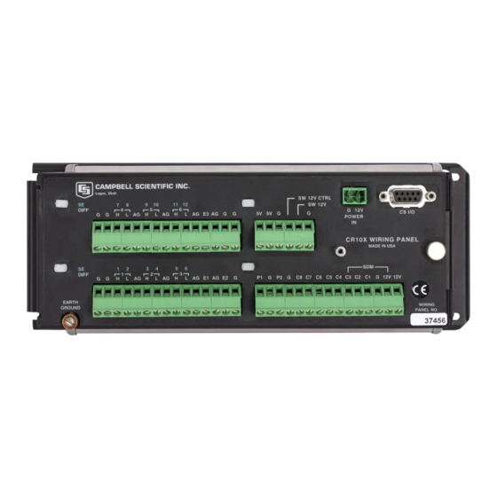
Wiring Panel224
-
-
Switched 12 Volt224
-
Maintenance226
-
Removing End Cap227
-
A. Glossary229
-
-
E. Ascii Table259
-
G.1 Introduction265
-
Baud Rate Codes303
-
List of Tables
345-
List of Figures349
-