
Related Manuals for Campbell MD9


Summary of Contents for Campbell MD9
-
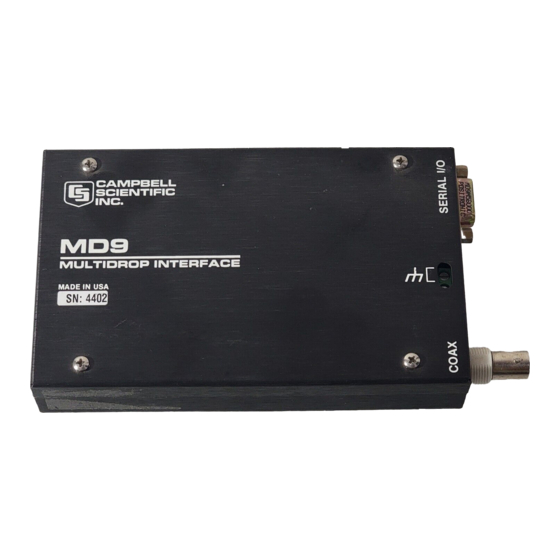
Page 1: Md9 Multidrop Interface
MD9 Multidrop Interface Revision: 5/03 C o p y r i g h t ( c ) 1 9 8 7 - 2 0 0 3 C a m p b e l l S c i e n t i f i c ,... - Page 2 CAMPBELL SCIENTIFIC, INC. CAMPBELL SCIENTIFIC, INC. will return such products by surface carrier prepaid. This warranty shall not apply to any CAMPBELL SCIENTIFIC, INC. products which have been subjected to modification, misuse, neglect, accidents of nature, or shipping damage. This warranty is in lieu of all other warranties, expressed or implied, including warranties of merchantability or fitness for a particular purpose.
-
Page 3: Table Of Contents
A. Cable Specifications and Source References..A-1 B. Break/Address Timing ........... B-1 C. Setting the Station ID ..........C-1 D. SC532A ..............D-1 Tables 1-1 Specifications ...................1 4-1 ID Settings for MD9 Connected to Computer ..........4 Figures 1-1 MD9 Multidrop Interface .................2 2-1 System Description...................3... - Page 4 MD9 Multidrop Interface Table of Contents 4-1 ID Switch and Baud Rate Selection Jumpers........... 4 6-1 Telephone to MD9 Conversion..............6 B-1 Break/Address Timing Diagram............B-1 This is a blank page.
-
Page 5: Introduction
Connection of the MD9 to the computer's RS-232 SIO port is made via the SC532(A) 9 Pin Peripheral to RS-232 Interface. The SC532(A) supplies +5 VDC power to the MD9 as well as converts the MD9's CMOS voltage levels to voltage levels consistent with RS-232 requirements. A computer with the PC201 card installed could use the SC925 Cable to connect directly to the MD9. -
Page 6: Md9 Multidrop Interface
Any branch cables from the main cable to an MD9 should be less than 10 feet in length. No terminator is used on the T connector at the MD9 on a branch. (Figure 2-1). -
Page 7: Software And Datalogger Compatibility
4. ID and Baud Rate Selection Each MD9 in an MD9 network must have a unique ID. The ID is set by the ID select switch (Figure 4-1). This switch is located under the cover, and can be accessed by removal of the four cover screws. -
Page 8: Maximum Number Of Dataloggers And Coax Length
The maximum coax run that can operate reliably is dependent on the signal loss due to the type of wire selected and the load placed on the system by each MD9 and coax terminator. The total signal loss in an MD9 system cannot be greater than 50 db. -
Page 9: Telephone To Md9 Network
The MD9 connected to the COM200 telephone modem must have the ID switch set to 255 (all switches open). When creating the station file in PC208 the base telephone with phone number is entered first and the MD9 with ID is entered second. -
Page 10: Operation
The signal is passed through the SC532(A) and in turn brings Pin 5 Modem Enable (ME) high on the MD9s I/O port. When the ME line is pulled high, the MD9 goes from State 0 standby to State 1 active. Once in State 1, any information transmitted by the computer is passed on to the coax network. - Page 11 FIRST "Interface Device", the software assumes the MD9 at the phone modem is in the Protocol Mode. If both conditions are met the MD9 ID set to 255 and the MD9 is not the first Interface Device the telephone to MD9 conversion is transparent to the user.
- Page 12 MD9 Multidrop Interface This is a blank page.
-
Page 13: Cable Specifications And Source References
Appendix A. Cable Specifications and Source References Belden 1505A: Conductor: 20 AWG solid copper (.032” ∅) Jacket Material: PVC Jacket O.D.: .235 Shield: Braided tinned copper (100% coverage) Resistance: 10Ω/1000’ Capacitance: 16.2pf/ft. Impedance: 75 Ohms Attenuation at 1 MHz: 0.29 db/100’ Belden Wire and Cable P.O. - Page 14 This is a blank page.
-
Page 15: Break/Address Timing
Appendix B. Break/Address Timing A BREAK consists of continuous spacing for time greater than 10 times the inverse of BR (baud rate). The BREAK is followed by a marking period and single byte ADDRESS. The marking time must be greater than one times the inverse of BR and the marking time and ADDRESS must be completed within 100 msec. - Page 16 This is a blank page.
-
Page 17: Setting The Station Id
Appendix C. Setting the Station ID Each MD9, including the one in the MD9 base station, must have a unique Station ID. Following is a list of all possible Station IDs with the corresponding setting of the dip switches. Here, 1 represents open and 0 is closed. - Page 18 Appendix C. Setting the Station ID SWITCHES SWITCHES SWITCHES 1234 5678 1234 5678 1234 5678 0001 0100 1100 1010 0111 1110 1001 0100 0010 1010 1111 1110 0101 0100 1010 1010 0000 0001 1000 0001 0011 0101 1110 1011 0100 0001 1011 0101...
-
Page 19: Sc532A
The correct barrel connector polarity is (+) on the inner bore and (−) on the outer sleeve. The MD9 requires that a minimum of 6 VDC @ 90 mA be supplied to the SC532A POWER jack from AC adapter or field cable. The maximum voltage that can be safely applied to the SC532A POWER jack is 17 VDC. - Page 20 This is a blank page.
- Page 21 This is a blank page.
- Page 22 Campbell Scientific Companies Campbell Scientific, Inc. (CSI) 815 West 1800 North Logan, Utah 84321 UNITED STATES www.campbellsci.com info@campbellsci.com Campbell Scientific Africa Pty. Ltd. (CSAf) PO Box 2450 Somerset West 7129 SOUTH AFRICA www.csafrica.co.za sales@csafrica.co.za Campbell Scientific Australia Pty. Ltd. (CSA)
Need help?
Do you have a question about the MD9 and is the answer not in the manual?
Questions and answers