Table of Contents
Advertisement
Quick Links
Advertisement
Table of Contents

Subscribe to Our Youtube Channel
Related Manuals for Campbell NL241


Summary of Contents for Campbell NL241
- Page 1 Revision: 10/2020 Copyright © 2011 – 2020 Campbell Scientific, Inc.
-
Page 2: Table Of Contents
Table of contents 1. Introduction 2. Precautions 3. QuickStart 3.1 Physical setup 3.2 Configuring the NL241 3.3 Loggerlink setup 3.4 Connect 4. Overview 4.1 Bridge mode enabled 4.2 Bridge mode disabled 5. Specifications 6. Wi-Fi 6.1 Introduction to Wi-Fi for WLANs 6.2 Wireless network modes... - Page 3 7. Configuring the NL241 7.1 Configuring the NL241 with Device Configuration Utility via USB 7.2 Configuring the NL241 with Device Configuration Utility via Wi-Fi WLAN 7.3 Configuring the NL241 with Telnet via Wi-Fi WLAN 7.4 Configuring the NL241 via RS-232 8.
- Page 4 8.2.6.2 Device Configuration Utility TCP encrypted communications to the NL241 9. Working around firewalls 9.1 Configuring the NL241 9.2 Configure the data logger 10. Troubleshooting Appendix A. Cables, pinouts, LED function, and jumper A.1 CS I/O A.2 RS-232 A.3 Link/Activity LED A.4 Power jumper...
- Page 5 B.2.6 EAP Password B.2.7 EAP Method B.2.8 Button Configuration B.2.9 Channel B.2.10 Tx Power Level B.2.11 Power Mode B.2.12 WLAN Domain Name B.2.13 Wireless Networks in Area B.3 RS-232 tab B.3.1 RS-232 Configuration B.3.2 RS-232 Service Port B.3.3 RS-232 Baud Rate B.3.4 RS-232 RTS B.3.5 RS-232 TCP Timeout B.3.6 RS-232 Always On...
- Page 6 B.7.1 TLS Status (read only) B.7.2 TLS Private Key Password B.7.3 TLS Private Key B.7.4 TLS Certificate Appendix C. Sending a new OS to the NL241 C.1 Sending an OS via USB C.2 Sending an OS via Wi-Fi Appendix D. Radio frequency emission...
-
Page 7: Introduction
The first time an NL241 is attached to a data logger and bridge mode is enabled, the data logger memory has to be reorganized to allow room in memory for the IP stack. To avoid the loss of data, collect your data before enabling bridge mode. -
Page 8: Quickstart
LED stops rapidly flashing red and green. 3. QuickStart Out of the box, the NL241 is configured for operation as a PakBus router and to create an open Wi-Fi network called “NL241_SerialNumber”. In this mode, the NL241 can be used to communicate with Campbell Scientific PakBus devices using a Wi-Fi-enabled device such as a smart phone. -
Page 9: Configuring The Nl241
3.2 Configuring the NL241 NOTE: Install the device driver before plugging the NL241 into your computer for the first time. The device driver must be properly installed before you can connect to the NL241 via USB. To install the device driver, download the latest version of Device Configuration Utility from our website. -
Page 10: Loggerlink Setup
(p. 45) for details on the password requirements. 11. Click the NL241 tab. 12. The default IP address of the NL241 is shown in the Status field and will be 192.168.67.1. To change the address, select disable in the DHCP Enabled field. Then type the IP Address, Network Mask, and Default Gateway. - Page 11 2. Connect your iOS or Android device to the Wi-Fi network created by the NL241 (“NL241_ SerialNumber,” by default). NOTE: Android users may get a message saying there is no internet access and be asked if you want to stay connected. Select the Don’t ask again for this network check box and click YES.
- Page 12 4. With TCP selected, click the UDP icon next to the Address field to automatically discover IP devices on the network. 5. Select the NL241 (address 192.168.67.1 by default). NL241 Wireless Network Link Interface...
- Page 13 6. The following screen appears. Click the PB icon to cause LoggerLink to search for attached PakBus devices. NOTE: For the PakBus search to work with the NL241, you must have LoggerLink version 1.6 or later. NL241 Wireless Network Link Interface...
-
Page 14: Connect
TCP Settings. Leave the Port at 6785. Select the data logger Type. Type the PakBus address of the data logger (default is 1) in the Address field under PakBus Settings. Type the NL241 PakBus address (default is 678) in the Neighbor field. The following screen shows the correct information filled in for a CR1000 with PakBus address of 2. -
Page 15: Overview
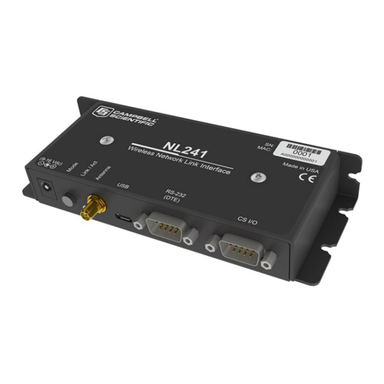
The NL241 Wireless Network Link Interface is designed for communications with Campbell Scientific data loggers and peripherals over a Wi-Fi network. The NL241 includes a CS I/O port and an RS-232 port for communications. A USB port is used for configuring the NL241 device. -
Page 16: Bridge Mode Enabled
TCP Serial Server, TCP Serial Client, Modbus TCP/IP Gateway, and PakBus router. The NL241 can act as a serial server and PakBus router simultaneously. However, each physical port (RS-232 and CS I/O) is only associated with one service (PakBus router, serial server, Modbus/TCP Gateway, etc.) at a time. - Page 17 CS I/O serial server, an RS-232 serial server and a CS I/O PakBus router, an RS-232 PakBus router and a CS I/O serial server, or an RS-232 PakBus router and a CS I/O PakBus router. In addition, the NL241 can act as TLS proxy server. The TLS proxy server is independent of other modes.
-
Page 18: Specifications
CS I/O or DC Barrel Connector (not USB) 9 to 16 VDC NOTE: To prevent the NL241 from being powered over the CS I/O port remove the internal jumper. Cables, pinouts, LED function, and jumper (p. 42) for more information. NL241 Wireless Network Link Interface... - Page 19 Access Point Mode: 67 mA idle, 70 mA communicating Standby: less than 1.5 mA NOTE: Standby power is when the NL241 Wi-Fi power has been turned off. This state can be IPNetPower() enabled by configuration of the Mode button or by using the...
- Page 20 Complies with the limits for a Class A digital device, pursuant to part 15 of the FCC Rules. Contains an embedded radio transmitter with the following approvals: FCC Identifier: XF6-RS9113SB View the Supplier Declaration of Conformity at www.campbellsci.com/nl241 Industry Canada: 8407A-RS9113SB View the EU Declaration of Conformity at www.campbellsci.com/nl241 NL241 Wireless Network Link Interface...
-
Page 21: Wi-Fi
Wi-Fi transmits at frequencies around 2.4 and 5 GHz (the NL241 only uses 2.4 GHz). The high frequency allows fast rates but reduced communications distance. These frequencies can be used by anyone and do not require a license from the FCC to use or transmit (unlike most UHF and VHF frequencies) as long as certain power levels are maintained. -
Page 22: Create A Network
6.2.2 Create a network The NL241 can be configured to create a network. In this mode, it acts as the access point which other Wi-Fi enabled devices can join. If this configuration is enabled, the user may set an SSID (network name) and password. -
Page 23: Rssi
RSSI is received signal strength indication. It is a generic radio receiver technology metric used to determine the strength of the link between a receiver and a transmitter. In the case of the NL241, RSSI is the measurement between the NL241 and a wireless access point. The strength of this link is recorded in dBm (power ratio in decibels) and can be found on the Wi-Fi tab in the Settings Editor of Device Configuration Utility. -
Page 24: Power
(p. 64). 6.6.1 Normal operation After power-up, the LED turns solid green while the NL241 is searching for and trying to join a Wi-Fi network. The LED turns solid amber when creating a network. After successfully joining or creating a network, the LED will flash with network activity. Note that the LED may only flash once every few seconds on the created network or networks that are not very busy. -
Page 25: Mode Button
NL241 without a valid operating system. Do not remove power until the LED resumes normal operationLink/Activity LED (p. 43) If an operating system upgrade includes an upgrade to the internal Wi-Fi module firmware, after the typical re-flashing of the LED, the device will power up and start copying the new firmware to the Wi-Fi module. -
Page 26: Temporarily Enable Wi-Fi
Configuration Utility via USB NOTE: Install the device driver before plugging the NL241 into your computer for the first time. The device driver must be properly installed before you can connect to the NL241 via USB. To install the device driver, download the latest version of Device Configuration Utility from our... -
Page 27: Configuring The Nl241 With Device Configuration Utility Via Wi-Fi Wlan
7.2 Configuring the NL241 with Device Configuration Utility via Wi-Fi WLAN NOTE: The NL241 is configured by default to host an open Wi-Fi network and have an IP address of 192.168.67.1. The network name will follow the pattern “NL241_SerialNumber.” 1. Apply power to the NL241. -
Page 28: Configuring The Nl241 With Telnet Via Wi-Fi Wlan
1. Apply power to the NL241. 2. The NL241 will power up and either create or join a Wi-Fi network. After successfully joining or creating a network, the LED will flash with network activity. Note that the LED may only flash once every few seconds on the created network or an idle network. -
Page 29: Configuring The Nl241 Via Rs-232
8. As each NL241 setting is shown, press Enter to accept the current value shown in parenthesis. Type a new value and press Enter to change the value. The up and down arrow keys on your keyboard can also be used to navigate through the settings. -
Page 30: Operation
8.1.1 Join an existing network In this configuration, the device will scan for available infrastructure networks and attempt to join the network specified by the SSID setting. 1. Connect to the NL241 in Device Configuration Utility (see Configuring the NL241 (p. 20)). -
Page 31: Operational Mode
When the RS-232 or CS I/O port is configured as a PakBus router, the NL241 can route packets to other devices in the network that it has in its routing table. These are devices that the NL241 has learned about through beaconing or allowed-neighbor lists. -
Page 32: Physical Setup
Neighbors Allowed (RS-232 port only) – Used to set a list of “acceptable neighbors” which the NL241 expects to hear from within set intervals (the verify interval). If the NL241 does not hear from neighbors in this list within the verify interval, it will attempt to contact them on its own. It will ignore all devices it hears that are not on the Neighbors Allowed list except if the PakBus address is ≥4000. -
Page 33: Loggernet Setup
8.2.1.3 LoggerNet setup 1. In the LoggerNet Setup screen, click Add Root and select IPPort. Enter the NL241 IP address and port number. The IP address and port number are input on the same line separated by a colon. -
Page 34: Connect
(p. 20)). On the NL241 tab, set Bridge Mode to enable. NOTE: In bridge mode, the IP address, subnet mask, and IP gateway to be used by the NL241 are configured in the data logger. 8.2.2.3 Configuring the data logger 1. -
Page 35: Loggernet Setup
By default, the NL241 uses the data logger CS I/O Interface #2. If connecting more than one NL241 to a data logger, one NL241 can be configured to use CS I/O Interface #1. This is done by connecting to the NL241 in DevConfig, going to the Settings Editor tab, and changing the CS I/O IP Interface Identifier from 2 to 1. -
Page 36: Connect
8.2.3.1 Physical setup Using the supplied serial cable, connect the NL241 CS I/O port or RS-232 port to the data logger CS I/O or RS-232 port, respectively. The NL241 will be powered if connected via CS I/O. Alternatively, power the NL241 through the barrel-connector jack located on the edge of the device. -
Page 37: Configuring The Nl241
NL241 has joined or created. 1. In the LoggerNet Setup screen, click Add Root and select IPPort. Enter the NL241 IP address and port number. The IP address and port number are input on the same line separated by a colon. -
Page 38: Connect
NL241. 8.2.4 TCP Serial Client When the RS-232 port is configured as TCP Serial Client, the NL241 will initiate and maintain a TCP socket connection to the IP address and port number specified by the Serial Client Address and Serial Client Port settings. -
Page 39: Modbus Tcp/Ip To Rtu Gateway
If the remote server closes the connection due to error, the NL241 will make a best effort to save any data that was in process and re-queue it to be sent on the next successfully-opened TCP connection. -
Page 40: Tls Proxy Server
Also, with the NL241 configured for TLS, it can establish a secure TLS configuration session with Device Configuration Utility. In order to use TLS, the user must configure the NL241 with a user-supplied TLS private key and TLS certificate. The key and certificate are loaded using Device Configuration Utility. - Page 41 In Configuration A, the NL241 decrypts TLS traffic and forwards the unencrypted TCP traffic to the data logger over the CS I/O port. The NL241 is able to “learn” the IP address of the attached data logger and will open a TCP connection on the “learned” IP address.
- Page 42 This address must be configured in the data logger. It must be a unique, static IP address on the same subnet as the NL241 IP address. For example, if the NL241 IP address is 192.168.5.1 with subnet 255.255.255.0, a valid IP address for the data logger would be 192.168.5.2 provided there are no other devices on the subnet with that address.
-
Page 43: Device Configuration Utility Tcp Encrypted Communications To The Nl241
In order to use Device Configuration Utility TCP encrypted communications with the NL241, you will need to load the TLS private key and TLS certificate into the NL241. This is done from the Settings Editor > TLS tab in Device Configuration Utility. Once the private key and certificate are loaded successfully, the TLS Status field should read Initialized. -
Page 44: Configuring The Nl241
3. On the Network Services tab: Under PakBus TCP Clients, input the NL241 IP address and PakBus TCP Service Port. 4. Click Apply to save the changes and then close Device Configuration Utility. NL241 Wireless Network Link Interface... -
Page 45: Troubleshooting
Verify that the antenna is securely attached to the NL241 and oriented in the same direction as the antenna of your WAP. The Link/Act LED on the NL241 should start flashing when it is connected to a network. Also, the WLAN activity light on your WAP (if it has one) should flash with activity as well. - Page 46 IP address of your NL241 followed by :6783 (for example, 192.168.0.3:6783). 7. If you are unable to communicate with the NL241 via the USB cable, verify that the latest drivers for the NL241 have been installed. These can be downloaded from our website at www.campbellsci.com.
- Page 47 Save a copy of the NL241 settings (in XML format) using Device Configuration Utility. c. Save a copy of the NL241 event log. This is low-level code that can be used by Campbell Scientific technical support to help troubleshoot the NL241. To obtain the event log, the NL241 must not be in bridge mode.
-
Page 48: Appendix A. Cables, Pinouts, Led Function, And Jumper
12 VDC (input) A.2 RS-232 A DB9 female to DB9 male cable is used to connect the NL241 RS-232 port to the data logger RS-232 port. The supplied SC12 cable can also be used. A DB9 female null modem cable is used to connect the NL241 RS-232 port to a computer RS-232 port. -
Page 49: Link/Activity Led
After successfully joining or creating a network, the LED will flash with network Flashing activity. Note that the LED may only flash once every few seconds on the created network or networks that are not very busy. NL241 Wireless Network Link Interface... -
Page 50: Power Jumper
A.4 Power jumper To prevent the NL241 from being powered over the CS I/O port, remove the two screws on the top of the NL241, remove the NL241 top cover, remove the jumper above the mode button and place it so that it is connected to only one post. With the jumper connected to only one post, the NL241 can only be powered from the barrel connector. -
Page 51: Appendix B. Nl241 Settings
Appendix B. NL241 settings All of the NL241 settings available from the Settings Editor in Device Configuration Utility are described below. B.1 Main tab B.1.1 Model (read only) Model name. B.1.2 Serial Number (read only) Specifies the NL241 serial number assigned by the factory. -
Page 52: Cs I/O Ip Interface Identifier
65535 (0xFFFF): Leave all bits set to forward all relevant packets. 65531 (0xFFFB): Clear bit 2 to forward all relevant packets except UDP Broadcast packets. Filtering UDP broadcasts will disable the data logger ability to respond to Device Configuration NL241 Wireless Network Link Interface... -
Page 53: Dhcp
If DHCP is enabled, the IP address obtained from the local DHCP server will be displayed in the Status box on the Deployment > NL241 tab. (It is recommended to configure a static IP address.) NOTE: In bridge mode, this setting is obtained from the data logger and cannot be edited here. -
Page 54: Dns Servers
DHCP server. B.1.14 Admin Password To help guard against unauthorized access to the NL241, it is password-protected by the admin password. This password will be required to gain access to the NL241 via Device Configuration Utility over TCP and Telnet. -
Page 55: Network Name (Ssid)
(approximately every 1 minute) retry. Create a Network The NL241 can be configured to create a network. In this mode, it acts as the access point which other Wi-Fi enabled devices can join. If this configuration is enabled, the user may set an SSID (network name) and password. -
Page 56: Password
The Wi-Fi network will continue to work as configured. Temporarily Enable Wi-Fi If this configuration is selected, the configured Wi-Fi network will normally be disabled and it will be activated temporarily when the button is pressed. NL241 Wireless Network Link Interface... -
Page 57: Channel
Medium (10 +/– 1 dBm), High (15 +/– 2 dBm). NOTE: This setting affects the transmission power level of the NL241, which may affect the transmission range of the device. This setting does not affect the overall power consumption of the device. -
Page 58: Wlan Domain Name
(SSID) may be listed here. B.3 RS-232 tab B.3.1 RS-232 Configuration This setting controls which process will be associated with the RS-232 port. The following values are defined: NL241 Wireless Network Link Interface... -
Page 59: Rs-232 Service Port
Ensure that the client application is set to use the same port number as configured here. Most MODBUS/TCP applications use port 502 (range 1 to 65535). NL241 Wireless Network Link Interface... -
Page 60: Rs-232 Baud Rate
B.3.4 RS-232 RTS The NL241 asserts the RTS and DTR lines when doing RS-232 communications. This setting allows the user to disable the RTS line if needed so that it will not be asserted. Some hardware will not function if the RTS line is asserted, but typically it is not necessary to change this setting from its default (enable). -
Page 61: Rs-232 Pakbus Beacon Interval
Power Down Port when Inactive. B.3.7 RS-232 PakBus Beacon Interval This setting, in units of seconds, governs the rate at which the NL241 will broadcast PakBus messages on the RS-232 port in order to discover any new PakBus neighboring nodes. It will also govern the default verification interval if the value of the RS -232 PakBus Verify Interval setting for the associated port is 0. -
Page 62: Rs-232 Modbus Timeout
MODBUS/TCP frames to MODBUS/RTU and forward them to the CS I/O port. The device will wait for a response from the MODBUS/RTU device and forward the response back to the remote MODBUS/TCP client over the established TCP connection. NL241 Wireless Network Link Interface... -
Page 63: Cs I/O Service Port
Set to 0 for no time-out (not recommended) (range 0 to 999). B.4.5 CS I/O PakBus Beacon Interval This setting, in units of seconds, governs the rate at which the NL241 will broadcast PakBus messages on the CS I/O port in order to discover any new PakBus neighboring nodes. It will also govern the default verification interval if the value of the CS I/O Verify Interval setting is set to 0. -
Page 64: Net Services Tab
Set to 0 for no time-out (not recommended) (range 0 to 999). B.5.4 Ping (ICMP) The NL241 will not respond to Ping requests if this setting is disabled. B.5.5 PakBus Address This setting specifies the PakBus address for this device. The value for this setting must be chosen such that the address of the device will be unique in the data logger network. -
Page 65: Pakbus/Tcp Password
(range 1 to 65535). B.5.10 PakBus Routes (read only) This setting lists the routes that are known to the NL241. Each route known to the NL241 will be represented by the following four components separated by commas and enclosed in parentheses. -
Page 66: Central Routers
When doing TLS Proxy communications, the NL241 TLS server maintains a secure connection with a remote client. If the TLS Proxy Forward Physical Port is set to CS I/O Port, the NL241 will open a TCP connection with the data logger over the CS I/O port and do unencrypted data transfer with the data logger. -
Page 67: Tls Proxy Forward Physical Port
IP address. If the TLS Proxy Forward Physical Port is specified to be the CS I/O Port, this setting does not need to be set by the user since the NL241 will obtain the IP address of the data logger automatically. The data logger must be configured with a static IP address that is unique and that exists on the same subnet as the NL241 IP address. -
Page 68: Tls Proxy Timeout
443. If a secure connection is established on this port, the NL241 will attempt to communicate to the data logger on the HTTP port 80. Leave this setting at its default unless the data logger is expecting communications on a different port (range 1 to 65535). -
Page 69: Tls Certificate
This setting can only be edited/transmitted if the Device Configuration Utility link is considered secure (USB or TLS). If the TLS stack has been initialized, the device will automatically negotiate a secure TLS connection with Device Configuration Utility if the Use TCP option is selected. NL241 Wireless Network Link Interface... -
Page 70: Appendix C. Sending A New Os To The Nl241
9. The operating system will be sent to the NL241. 10. After the file has been sent, the LED on the NL241 will flash repeatedly while the NL241 copies the OS into its internal flash. Depending upon the operating system that was previously installed, it may take up to 2 minutes for the NL241 to finish updating the operating system. -
Page 71: Sending An Os Via Wi-Fi
Follow these steps to send the new OS to the NL241 via Wi-Fi: 1. Using the supplied serial cable, connect the NL241 CS I/O port to the data logger CS I/O port. Alternatively, power the NL241 through the barrel-connector jack located on the edge of the device. -
Page 72: Appendix D. Radio Frequency Emission
Appendix D. Radio frequency emission Changes or modifications to the NL241 not expressly approved by Campbell Scientific, Inc. could void the user’s authority to operate this product. NOTE: This equipment has been tested and found to comply with the limits for a Class A digital device, pursuant to part 15 of the FCC Rules. - Page 73 See Product Details on the Ordering Information pages at www.campbellsci.com. Other manufacturer's products, that are resold by Campbell Scientific, are warranted only to the limits extended by the original manufacturer.
- Page 74 Campbell Scientific office serves your country. To obtain a Returned Materials Authorization or Repair Reference number, contact your CAMPBELL SCIENTIFIC regional office. Please write the issued number clearly on the outside of the shipping container and ship as directed.
- Page 75 Do not recharge, disassemble, heat above 100 °C (212 °F), solder directly to the cell, incinerate, or expose contents to water. Dispose of spent batteries properly. WHILE EVERY ATTEMPT IS MADE TO EMBODY THE HIGHEST DEGREE OF SAFETY IN ALL CAMPBELL SCIENTIFIC PRODUCTS, THE CUSTOMER ASSUMES ALL RISK FROM ANY INJURY RESULTING FROM IMPROPER INSTALLATION, USE, OR MAINTENANCE OF TRIPODS, TOWERS, OR...
- Page 76 Campbell Scientific regional offices Australia France Thailand Location: Garbutt, QLD Australia Location: Vincennes, France Location: Bangkok, Thailand Phone: 61.7.4401.7700 Phone: 0033.0.1.56.45.15.20 Phone: 66.2.719.3399 Email: info@campbellsci.com.au Email: info@campbellsci.fr Email: info@campbellsci.asia Website: www.campbellsci.com.au Website: www.campbellsci.fr Website: www.campbellsci.asia Brazil Germany Location: São Paulo, SP Brazil...
Need help?
Do you have a question about the NL241 and is the answer not in the manual?
Questions and answers