
Related Manuals for Campbell MD485


Summary of Contents for Campbell MD485
- Page 1 PRODUCT MANUAL MD485 RS-485 Multidrop Interface Revision: 09/2024 Copyright © 2003 – 2024 Campbell Scientific, Inc.
- Page 2 U.S. standard external power supply details where some information (for example the AC transformer input voltage) will not be applicable for British/European use. Please note, however, that when a power supply adapter is ordered from Campbell Scientific it will be suitable for use in your country.
- Page 3 7.2 Grounding 7.3 Protection and isolation 7.4 Termination 7.5 Summary Appendix A. Phone to MD485 network Appendix B. RF401A to MD485 network B.1 Connection using a PS150 with A100 B.2 Connection using a null modem cable Appendix C. MD485 to RF401A network C.1 Connection using a PS150 with A100...
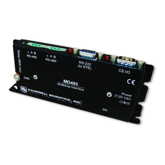
- Page 4 1. Introduction The MD485 is an intelligent RS-485 interface. It is configurable to use any two of its three interface ports (RS-485, RS-232 and CS I/O) at a time. The primary function of the MD485 device is to provide a connection to an RS-485 network (using CS I/O or RS-232).
- Page 5 8 AWG wire. This connection should be as short as possible. 3.2 MD485 indicator LEDs The MD485 has two red LEDs. When 12V power is applied, the LEDs light for one second. The LEDs then begin flashing once every two seconds, while there is no activity on the ports.
- Page 6 Campbell Scientific also offers a wall transformer that supports 120 VAC. A 12 V supply may connect to either the MD485 DC Pwr jack or CS I/O pin 8 (or both, since there is diode isolation between supply inputs). The 12 V supply inputs are diode protected against the application of reverse polarity power.
- Page 7 In an MD485 base station, a straight-through DB9M/DB9F RS-232 cable will connect from the MD485 RS-232 port to the computer COM port. This cable is included with the MD485. A remote MD485 normally uses the included SC12 cable to connect the MD485 CS I/O port to the data logger CS I/O port.
- Page 8 Connect serial cable from computer COM port to base MD485 RS-232 port. b. Plug transformer into AC outlet and plug barrel connector into base MD485 DC Pwr jack. You will see both red LEDs light immediately for 1 second. Both LEDs then begin to flash once every 2 seconds.
- Page 9 Figure 4-1. MD485 basic point-to-point network 2. Set up remote MD485 a. Connect SC12 cable from data logger CS I/O port to remote MD485 CS I/O port. Current data logger/wiring panel CS I/O ports apply power to the remote MD485.
- Page 10 Click Connect. f. Change Active Ports to CS I/O and RS-485, then click Apply. 3. Connect the CABLE2TP cable from the 3-pin terminal block on the base MD485 to the 3- pin terminal block on the remote MD485 as described in RS-485 cable (p.
- Page 11 (p. 8) depicts the connection of a computer to a network of Campbell Scientific data loggers using MD485s. Figure 5-1. MD485 point-to-multipoint network The base MD485 is connected to the computer COM port with a serial cable. A transformer supplies +12 VDC power to the MD485. MD485 RS-485 Multidrop Interface...
- Page 12 The MD485 at the computer is connected to one or more remote MD485s with the CABLE2TP cable. The MD485 at the data logger is connected via an SC12 cable (supplied with the MD485) and is powered from the data logger CS I/O port.
- Page 13 Functioning as a transparent device, the MD485 becomes somewhat protocol independent. It acts as a way to get from one physical interface to another. In this mode the MD485 uses what is called “send-data” transmit control. The 485 transceiver is normally set to receive. When data needs to be transmitted on the RS-485 link, the driver is enabled, and stays enabled for 1 character tone after the last byte is sent.
- Page 14 MD485 closest to the computer. The base MD485 has RS-232 and RS-485 chosen as active ports, while the remote MD485 has the active ports set to RS-485 and CS I/O. Figure 5-4. Long distance RS-232 to CS I/O conversion Figure 5-5 (p.
- Page 15 RS-485 side. This allows reliable peer-to-peer networking of multiple devices over the three-wire RS-485 interface. When the communications mode is set to PakBus Networking, the MD485 does not need to be represented in the device map of LoggerNet. The data loggers are simply attached to a PakBusPort.
- Page 16 (p. 8), it is possible to combine methods in data logger communications. Some combined communications examples: Phone to MD485: computer to external modem to COM220 to PS150 with A100 to MD485 to MD485 to data logger (see Phone to MD485 network [p.
- Page 17 7.2 Grounding The MD485 has a ground lug. Connect this ground lug to earth ground with an 8 AWG wire. This connection should be as short as possible. The differential signaling of RS-485 does not require a signal ground to communicate. The standard allows for a common-mode voltage (Vcm) of -7 to +12 V.
- Page 18 7.5 Summary Use CABLE2TP-L 2-twisted-pair cable with shield and Santoprene jacket for most installations. Connect the MD485 ground lug to earth ground with an 8 AWG wire. This connection should be as short as possible. Connect the signal ground wire between MD485s.
- Page 19 PS150 Power Supply and A100 Null Modem Adapter to communicate with an MD485. The COM220 and the MD485 are both supplied with a 9 pin SC12 cable suitable for connection to the A100. The PS150 provides 5 and 12 volts for system operation and the A100 performs the function of a null modem (the COM220 and MD485 are both "modem"...
- Page 20 Figure A-1. Telephone to MD485 conversion Where a phone to MD485 base is desired, the following configurations will provide point-to- point or point-to-multipoint communications. 1. HARDWARE REQUIREMENTS a. MD485s b. COM220 c. PS150 with A100 d. Transformer or solar panel e.
- Page 21 RS-485 Port Configuration – Desired baud rate 3. HARDWARE After configuring LoggerNet and the MD485s, you are ready to set up hardware. The A100 null modem connectors (it’s not important which connector goes to which unit) connect MD485 RS-485 Multidrop Interface...
- Page 22 SC12 cables to the COM220 and the base MD485 CS I/O port. Connect the site phone line to COM220. Connect power to PS150. When you turn on the PS150 supply, the MD485 receives 12 V power and you will see the LEDs light in their power-up sequence.
- Page 23 (the RF401A and MD485 are both "modem" devices). 2) Using a null modem cable and transformers to provide power to the RF401A and the MD485. The following sections will describe how to set up the RF401A to MD485 network using each of these two methods for each communications mode.
- Page 24 RF401As c. PS150 with A100 d. Transformer for base RF401A e. Transformer or solar panel for PS150 f. Three SC12 cables (one included with each MD485 and one with RF401A) g. CABLE2TP 2. TRANSPARENT COMMUNICATIONS (POINT-TO-POINT) Computer-RF401A---RF401A-PS150 with A100-MD485---MD485-DL...
- Page 25 (it’s not important which connector goes to which unit) connect via SC12 cables to the CS I/O ports of the remote RF401A and the base MD485. Connect power to the PS150. When you turn on the PS150 supply, the MD485 receives 12 V power and you will see the LEDs light in their power-up sequence.
- Page 26 RS-485 ports of the base and remote MD485s and you are ready to connect to the data logger. B.2 Connection using a null modem cable The RF401A to MD485 conversion can be done using a null modem cable in place of the PS150/A100. The following configurations will provide communications in transparent mode or PakBus networking.
- Page 27 Computer-RF401A---RF401A---null modem---MD485 ---MD485-DL1 ---MD485-DL2 LoggerNet Setup a. Setup: ComPort_1 PakBus Port CR1000X CR1000X_2 b. ComPort_1 – default settings c. PakBus Port – defaults d. Data loggers – corresponding PakBus address, other setting default, schedule collections as desired MD485 RS-485 Multidrop Interface...
- Page 28 Remote MD485s i. Active Ports – CS I/O and RS-485 ii. Protocol Configuration – PakBus Networking iii. CS I/O Mode – SDC Address 7 or SDC Address 8 iv. RS-485 Port Configuration – Desired baud rate MD485 RS-485 Multidrop Interface...
- Page 29 Connect the base RF401A RS-232 port to the computer COM port. Attach the null modem cable to the RS-232 ports of the remote RF401A and the base MD485. Attach transformers to the DC Pwr jack of each RF401A and the base MD485.
- Page 30 (the RF401A and MD485 are both "modem" devices). 2) Using a null modem cable and transformers to provide power to the RF401A and the MD485. The following sections will describe how to set up the MD485 to RF401A network using each of these two methods for each communications mode.
- Page 31 RF401As c. PS150 with A100 d. Transformer for base MD485 e. Transformer for solar panel for PS150 f. Three SC12 cables (one included with MD485 and one with each RF401A) g. CABLE2TP cable 2. TRANSPARENT COMMUNICATIONS (POINT-TO-POINT) Computer-MD485---MD485-PS150 with A100-RF401A---RF401A-DL LoggerNet Setup a.
- Page 32 MD485 and the base RF401A. Connect power to the PS150. When you turn on the PS150 supply, the MD485 and the RF401A receive 12 V power and you will see the LEDs light in their power-up sequence.
- Page 33 C.2 Connection using a null modem cable The MD485 to RF401A conversion can be done using a null modem cable in place of the PS150/A100. The following configurations will provide communications in transparent mode or PakBus networking. 1. HARDWARE REQUIREMENTS a.
- Page 34 MD485 Configuration a. Base MD485 i. Active Ports – RS-232 and RS-485 ii. Protocol Configuration – PakBus Networking b. Remote MD485s i. Active Ports – RS-232 and RS-485 ii. Protocol Configuration – PakBus Networking MD485 RS-485 Multidrop Interface...
- Page 35 Connect the base MD485 RS-232 port to the computer COM port. Attach the null modem cable to the RS-232 ports of the remote MD485 and the base RF401A. Attach transformers to the DC Pwr jack of each MD485 and the base RF401A.
- Page 36 12 V supplied by Data logger sources 12 VDC to power peripherals data logger Serial data transmit line I = Signal into the MD485, O = Signal out of the MD485, NC = No connection MD485 RS-485 Multidrop Interface...
- Page 37 Equipment (DCE) for direct cable connection to Data Terminal Equipment (DTE) such as a computer serial port. Table D-2: RS-232 connector, 9-pin D-sub female Function I = Signal into the MD485, O = Signal out of the MD485, NC = No connection RS-485 Port Table D-3: RS-485 connector, 3-pin terminal block Function...
- Page 38 2. The defect cannot be the result of misuse. 3. The defect must have occurred within a specified period of time; and 4. The determination must be made by a qualified technician at a Campbell Scientific Service Center/ repair facility.
- Page 39 Campbell Scientific’s Terms, the provisions of Campbell Scientific’s Terms shall prevail. Furthermore, Campbell Scientific’s Terms are hereby incorporated by reference into this Warranty. To view Terms and conditions that apply to Campbell Scientific, Logan, UT, USA, see Terms and Conditions ...
- Page 40 Please state the faults as clearly as possible. Quotations for repairs can be given on request. It is the policy of Campbell Scientific to protect the health of its employees and provide a safe working environment. In support of this policy, when equipment is returned to Campbell Scientific, Logan, UT, USA, it is mandatory that a “Declaration of Hazardous Material and...
- Page 41 Comply with all electrical codes. Electrical equipment and related grounding devices should be installed by a licensed and qualified electrician. Only use power sources approved for use in the country of installation to power Campbell Scientific devices. Elevated Work and Weather Exercise extreme caution when performing elevated work.
- Page 42 Periodically (at least yearly) check electrical ground connections. WHILE EVERY ATTEMPT IS MADE TO EMBODY THE HIGHEST DEGREE OF SAFETY IN ALL CAMPBELL SCIENTIFIC PRODUCTS, THE CUSTOMER ASSUMES ALL RISK FROM ANY INJURY RESULTING FROM IMPROPER INSTALLATION, USE, OR MAINTENANCE OF TRIPODS,...
- Page 43 Campbell Scientific Regional Offices Australia France Spain Location: Garbutt, QLD Australia Location: Montrouge, France Location: Barcelona, Spain Phone: 61.7.4401.7700 Phone: 0033.0.1.56.45.15.20 Phone: 34.93.2323938 Email: info@campbellsci.com.au Email: info@campbellsci.fr Email: info@campbellsci.es Website: www.campbellsci.com.au Website: www.campbellsci.fr Website: www.campbellsci.es Brazil Germany Thailand Location: São Paulo, SP Brazil...
Need help?
Do you have a question about the MD485 and is the answer not in the manual?
Questions and answers