
Subscribe to Our Youtube Channel
Related Manuals for Campbell NL200


Summary of Contents for Campbell NL200
- Page 1 PRODUCT MANUAL NL200/201 Network Link Interface Revision: 04/2024 Copyright © 2011 – 2024 Campbell Scientific, Inc.
- Page 2 U.S. standard external power supply details where some information (for example the AC transformer input voltage) will not be applicable for British/European use. Please note, however, that when a power supply adapter is ordered from Campbell Scientific it will be suitable for use in your country.
- Page 3 4.1 Bridge mode enabled 4.2 Bridge mode disabled 5. Specifications 6. Configuring the NL200/201 6.1 Configuring the NL200/201 with Device Configuration Utility via USB 6.2 Configuring the NL200/201 with Device Configuration Utility via network connection 6.3 Configuring the NL200/201 with Telnet 6.4 Configuring the NL200/201 via RS-232...
- Page 4 9. Troubleshooting 10. Attributions Appendix A. Network examples A.1 NL200/201 with radio network A.1.1 Configure the NL200/201 as a PakBus router A.1.2 Configure radio connected to the NL200/201 A.1.2.1 RF407-series A.1.2.2 RF451/452 A.1.3 Configure radio connected to the data logger A.1.3.1 RF407-series...
- Page 5 A.2.3 NL200/201 physical setup A.2.4 Configure the NL200/201 A.2.5 Configure the data logger A.2.6 Setup LoggerNet A.3 CR300 over IP to Konect A.3.1 NL200/201 physical setup A.3.2 Configure the NL200/201 A.3.3 Configure the data logger (CR300) A.3.4 Setup LoggerNet Appendix B. Cables, pinouts, LED function, and jumper B.1 CS I/O...
- Page 6 C.2.1 RS-232 Configuration C.2.2 RS-232 Service Port C.2.3 RS-232 Baud Rate C.2.4 RS-232 RTS C.2.5 RS-232 TCP Timeout (seconds) C.2.6 RS-232 PakBus Beacon Interval C.2.7 RS-232 PakBus Verify Interval C.2.8 Neighbors Allowed RS-232 C.2.9 RS-232 Modbus Timeout C.2.10 RS-232 TCP Serial Client IP Address C.2.11 RS-232 TCP Serial Client Port C.3 CS I/O tab C.3.1 CS I/O Configuration...
- Page 7 C.6.1 TLS Status (read only) C.6.2 TLS Private Key Password C.6.3 TLS Private Key C.6.4 TLS Certificate Appendix D. Sending a new OS to the NL200/201 D.1 Sending an OS via USB D.2 Sending an OS via IP Appendix E. Glossary...
- Page 8 The first time an NL200/201 is attached to a data logger and bridge mode is enabled, the data logger memory has to be reorganized to allow room in memory for the IP stack. To avoid the loss of data, collect your data before enabling bridge mode.
- Page 9 LED stops rapidly flashing red and green. 3. QuickStart Out of the box, the NL200/201 is configured for operation as a PakBus router. In this mode, the NL200/201 can be used to communicate with Campbell Scientific PakBus devices over an Ethernet / Internet network connection.
- Page 10 Figure 3-1. NL201 with CR800 (powered by data logger) Figure 3-2. NL200 with CR800 (external power) NL200/201 Network Link Interface 3...
- Page 11 255.255.255.0. 11. If a dynamic address is to be used, the network information acquired via DHCP can be seen on the NL200 Series tab under Status. The Status box also displays the MAC address of the NL200/201.
- Page 12 The next step is to run LoggerNet and configure it to connect to the data logger via the NL200/201. 1. In the LoggerNet Setup screen, click Add Root and select IPPort. Enter the NL200/201 IP address and port number. The IP address and port number are input on the same line separated by a colon.
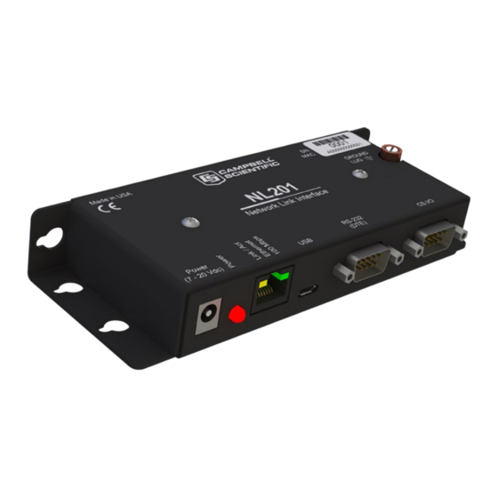
- Page 13 The NL200/201 Network Link Interface is designed for communications with Campbell Scientific data loggers and peripherals using an Ethernet 10/100 Mbps communications link. The NL200/201 includes a CS I/O port and an RS-232 port for communications. A USB port is used for configuring the NL200/201 device.
- Page 14 CS I/O serial server, an RS-232 serial server and a CS I/O PakBus router, an RS-232 PakBus router and a CS I/O serial server, or an RS-232 PakBus router and a CS I/O PakBus router. In addition, the NL200/201 can act as TLS proxy server. The TLS proxy server is independent of other modes.
- Page 15 4.1 Bridge mode enabled The NL200/201 can be configured to bridge Ethernet and CS I/O communications (see the following figure). This mode is used for providing access to the internal IP functionality of the CR6, CR800/850, CR1000, and CR3000 (for example, webpage access, email, FTP, etc.). Bridge mode does not use PPP.
- Page 16 CS I/O serial server, or an RS-232 PakBus router and a CS I/O PakBus router. In addition, the NL200/201 can act as TLS proxy server. The TLS proxy server is independent of other modes. The Secure Proxy Server can forward unsecured traffic to a single device. That device may be accessed via Ethernet or CS I/O.
- Page 17 NL200: DC Barrel connector (not USB) 7 to 20 VDC 600 mW active, 24 mW standby NOTE: To prevent the NL200/201 from being powered over the CS I/O port remove the internal jumper. See Cables, pinouts, LED function, and jumper (p. 45) for more information.
- Page 18 Supports 50 simultaneous TCP connections Up to 10 of the 50 TCP connections can be used for TLS PakBus router supports 50 routes Supports up to 15 concurrent Modbus server transactions Compliance View documents at: www.campbellsci.com/nl201 NL200/201 Network Link Interface 11...
- Page 19 6.1 Configuring the NL200/201 with Device Configuration Utility via USB NOTE: Install the device driver before plugging the NL200/201 into your computer for the first time. The device driver must be properly installed before you can connect to the NL200/201 via USB.
- Page 20 NOTE: The NL200/201 must have an IP address before connecting via a network connection. If the address cannot be obtained via DHCP, you will need to configure your NL200/201 via USB the first time it is set up. 1. Apply power to the NL200/201.
- Page 21 It can be changed via the Device Configuration Utility Deployment > NL200 Series tab.) 4. Type help to see a list of the functionality available when connected to the NL200/201. 5. Type edit and press Enter to edit the settings of the NL200/201.
- Page 22 Generally, the Verify Interval should be set greater than or equal to the interval at which you will be talking to the attached PakBus devices. For example, if the NL200/201 is being used as a PakBus router to allow scheduled collection of a network of data loggers every 15 minutes, consider setting the Verify Interval to 30 minutes.
- Page 23 Connect the NL200/201 to your network using an Ethernet cable, attaching one end of the cable to the NL200/201 Ethernet port and the other end to your network. Ensure that the device is powered up by inspecting the Power LED.
- Page 24 LoggerNet Setup after the IP address. 7.1.3 LoggerNet setup 1. In the LoggerNet Setup screen, click Add Root and select IPPort. Enter the NL200/201 IP address and port number. The IP address and port number are input on the same line separated by a colon.
- Page 25 Configuration Port Number is a user setting with a default value of 6786. 7.2.1 Physical setup Using the supplied serial cable, connect the NL201 CS I/O port to the data logger CS I/O port. Alternatively, power the NL200 or NL201 through the barrel-connector jack located on the edge NL200/201 Network Link Interface 18...
- Page 26 Connect the NL200/201 to your network using an Ethernet cable, attaching one end of the cable to the NL200/201 Ethernet port and the other end to your network. Ensure that the device is powered up by inspecting the Power LED.
- Page 27 You are now ready to connect to your data logger using LoggerNet. Select Main and Connect on the LoggerNet toolbar, select the data logger from the Stations list, then Connect. From there, you can view and collect data, or manage data logger settings. NL200/201 Network Link Interface 20...
- Page 28 Connect the NL200/201 to your network using an Ethernet cable, attaching one end of the cable to the NL200/201 Ethernet port and the other end to your network. Ensure that the device is powered up by inspecting the Power LED.
- Page 29 The next step is to run LoggerNet and configure it to connect to the data logger via the Ethernet port. (See the following screen shot.) 1. In the LoggerNet Setup screen, click Add Root and select IPPort. Enter the NL200/201 IP address and port number. The IP address and port number are input on the same line separated by a colon.
- Page 30 NL200/201. 7.4 TCP Serial Client When the RS-232 port is configured as TCP Serial Client, the NL200/201 will initiate and maintain a TCP socket connection to the IP address and port number specified by the Serial Client Address and Serial Client Port settings.
- Page 31 If the remote server closes the connection due to error, the NL200/201 will make a best effort to save any data that was in process and re-queue it to be sent on the next successfully-opened TCP connection.
- Page 32 Also, with the NL200/201 configured for TLS, it can establish a secure TLS configuration session with Device Configuration Utility. In order to use TLS, the user must configure the NL200/201 with a user-supplied TLS private key and TLS certificate. The key and certificate are loaded using Device Configuration Utility.
- Page 33 In Configuration A, the NL200/201 decrypts TLS traffic and forwards the unencrypted TCP traffic to the data logger over the CS I/O port. The NL200/201 is able to “learn” the IP address of the attached data logger and will open a TCP connection on the “learned” IP address.
- Page 34 TCP connection to the data logger and forward the unencrypted data. In HTTPS communications, web browsers use port 443. The NL200/201 will always listen on port 443 regardless of the value of this setting. Therefore, if HTTPS communications are desired, it is unnecessary to configure this setting.
- Page 35 In order to use Device Configuration Utility TCP encrypted communications with the NL200/201, you will need to load the TLS private key and TLS certificate into the NL200/201. This is done from the Settings Editor > TLS tab in Device Configuration Utility. Once the private key and certificate are loaded successfully, the TLS Status field should read Initialized.
- Page 36 The NL200/201 can be used to provide a connection between LoggerNet and a data logger when both are behind firewalls as shown in the following figure. The NL200/201 must be on a public IP address and will act as a common meeting place for all PakBus communications.
- Page 37 Communication Port, and Baud Rate. Click Connect to connect to the data logger. 3. On the Network Services tab input the NL200/201IP address and PakBus TCP Service Port in the PakBus TCP Clients area. 4. Click Apply to save the changes and then close Device Configuration Utility.
- Page 38 LoggerNet Setup, enter the correct IP address of your NL200/201 followed by :6783 (for example, 192.168.0.3:6783). 7. If you are unable to communicate with the NL200/201 via the USB cable, verify that the latest drivers for the NL200/201 have been installed. These can be downloaded from our website at www.campbellsci.com/downloads...
- Page 39 Save a copy of the NL200/201 settings (in XML format) using Device Configuration Utility. c. Save a copy of the NL200/201 event log. This is low-level code that can be used by Campbell Scientific technical support to help troubleshoot the NL200/201. To obtain the event log, the NL200/201 must not be in bridge mode.
- Page 40 WARRANTIES, INCLUDING, BUT NOT LIMITED TO, THE IMPLIED WARRANTIES OF MERCHANTABILITY AND FITNESS FOR A PARTICULAR PURPOSE ARE DISCLAIMED. IN NO EVENT NL200/201 Network Link Interface 28 SHALL THE AUTHOR BE LIABLE FOR ANY DIRECT, INDIRECT, INCIDENTAL, SPECIAL, EXEMPLARY, OR CONSEQUENTIAL DAMAGES (INCLUDING, BUT NOT LIMITED TO, PROCUREMENT OF SUBSTITUTE GOODS OR SERVICES;...
- Page 41 2. On the NL200 Series tab, set Bridge Mode to disable. 3. If a dynamic address is to be used, the network information acquired via DHCP can be seen on the NL200 Series tab under Status. The Status box also displays the MAC address of the NL200/201.
- Page 42 (p. 37). A.1.2 Configure radio connected to the NL200/201 Using a USB cable, connect to the radio that will be connected to the NL200/201. Either an RF407-series or RF451/452 can be used. See those product manuals for additional details. A.1.2.1 RF407-series 1.
- Page 43 2. Click the Factory Defaults button at the bottom of the Deployment window. 3. On the Com Ports Settings tab set: a. ComPort to CS I/O SDC7 b. Beacon Interval to 60 (seconds) 4. Click Apply to save the changes and then close Device Configuration Utility. NL200/201 Network Link Interface 36...
- Page 44 A.1.5 Setup LoggerNet 1. In the LoggerNet Setup screen, click Add Root and select IPPort. Enter the NL200/201 IP address and port number. The IP address and port number are input on the same line separated by a colon. IPv6 addresses will need to be enclosed in square brackets when specifying a port number.
- Page 45 Ethernet cable. A.2.1 CELL200-series physical setup 1. Connect the CELL200-series and NL200/201 RS-232 ports using a straight-through RS-232 pin to socket cable such as an SC12. 2. Connect the cellular antenna, if it is not already connected.
- Page 46 3. On the NL200 Series tab, set Bridge Mode to disable. 4. If a dynamic address is to be used, the network information acquired via DHCP can be seen on the NL200 Series tab under Status. The Status box also displays the MAC address of the NL200/201.
- Page 47 NOTE: The IP Gateway does not need to be set. 5. On the Network Services tab set the PakBus/TCP Clients Address to that of the NL200/201: 192.168.1.2. This will cause the data logger to communicate with the NL200/201 over PakBus.
- Page 48 2. Add PakBusPort (PakBus Loggers). 3. Add a PakBus Router (pbRouter). Enter the PakBus address of the NL200/201. The NL200/201 default PakBus address is 678. Click Close. 4. Add the data logger and enter its PakBus address.
- Page 49 3. On the NL200 Series tab, set Bridge Mode to disable. 4. If a dynamic address is to be used, the network information acquired via DHCP can be seen on the NL200 Series tab under Status. The Status box also displays the MAC address of the NL200/201.
- Page 50 1. In the LoggerNet Setup screen, click Add Root and select IPPort. Enter the Konect PakBus Router IP address and port number of the NL200/201. The IP address and port number are input on the same line separated by a colon. IPv6 addresses will need to be enclosed in square brackets when specifying a port number.
- Page 51 5. Add another PakBus Router (pbRouter). Enter the PakBus address of the NL200/201. The NL200/201 default PakBus address is 678. Click Close. 6. Add the data logger and enter its PakBus address. NOTE: The CR300 and NL200/201 must have different PakBus addresses.
- Page 52 Pin configuration for the CS I/O port and connected peripheral device is shown in the following Table. Table B-1: CS I/O pinout Data logger (DB9 socket) Peripheral (DB9 pin) function function 5 VDC Not connected SIGNAL GND SIGNAL GND RING RING CLK/HS CLK/HS NL200/201 Network Link Interface 45...
- Page 53 NL201: 12 VDC (input) B.2 RS-232 A DB9 pin and socket cable is used to connect the NL200/201 RS-232 port to the data logger RS-232 port. A Campbell Scientific SC12 cable can also be used. A DB9 socket null modem cable is used to connect the NL200/201 RS-232 port to a computer RS-232 port.
- Page 54 NOTE: The maximum recommended segment length for 10BaseT and 100BaseTx networks using CAT5 cable is 100 meters. Segment length is the length of cable between the NL200/201 and the Ethernet repeater, hub, switch, or router it is connected to. Table B-3: Ethernet pinout...
- Page 55 With the jumper connected to only one post, the NL201 can only be powered from the barrel connector. With the jumper connected to both posts, the NL201 can be powered from the CS I/O port or from the barrel connector. NL200/201 Network Link Interface 48...
- Page 56 NL200/201 Network Link Interface 49...
- Page 57 Appendix C. NL200/201 settings The NL200/201 settings available from the Settings Editor in Device Configuration Utility are described as follows. C.1 Main tab C.2 RS-232 tab C.3 CS I/O tab C.4 Net Services tab C.5 TLS Proxy Server tab C.6 TLS tab C.1 Main tab...
- Page 58 Ethernet processing the data logger needs to perform. It may be desired to further reduce the amount of CS I/O traffic. This setting allows the filtering by the device to be customized to some degree. The default value of this setting is 65535 (0xFFFF NL200/201 Network Link Interface 51...
- Page 59 If DHCP is enabled, the IP address obtained from the local DHCP server will be displayed in the Status box on the Deployment > NL200 Series tab. (It is recommended to configure a static IP address.) NOTE: In bridge mode, this setting is obtained from the data logger and cannot be edited here.
- Page 60 IP address. If DHCP is enabled, the subnet mask obtained from the local DHCP server will be displayed in the Status box on the Deployment > NL200 Series tab. NOTE: In bridge mode, this setting is obtained from the data logger and cannot be edited here.
- Page 61 This password will be required to gain access to the NL200/201 via Device Configuration Utility over TCP and Telnet. If the password setting is left blank, no password is required to access the NL200/201. After settings are saved, the new password will be in effect. C.1.16 TCP Configuration Port Number The default TCP port number for configuration via TCP is 6786.
- Page 62 C.2.4 RS-232 RTS The NL200/201 asserts the RTS and DTR lines when doing RS-232 communications. This setting allows the user to disable the RTS line if needed so that it will not be asserted. Some hardware will...
- Page 63 (not recommended) (range 0 to 999 seconds). C.2.6 RS-232 PakBus Beacon Interval This setting, in units of seconds, governs the rate at which the NL200/201 will broadcast PakBus messages on the RS-232 port in order to discover any new PakBus neighboring nodes. It will also govern the default verification interval if the value of the RS -232 PakBus Verify Interval setting for the associated port is 0.
- Page 64 MODBUS/TCP frames to MODBUS/RTU and forward them to the CS I/O port. The device will wait for a response from the MODBUS/RTU device and forward the response back to the remote MODBUS/TCP client over the established TCP connection. NL200/201 Network Link Interface 57...
- Page 65 Set to 0 for no time-out (not recommended) (range 0 to 999). C.3.5 CS I/O PakBus Beacon Interval This setting, in units of seconds, governs the rate at which the NL200/201 will broadcast PakBus messages on the CS I/O port in order to discover any new PakBus neighboring nodes. It will also govern the default verification interval if the value of the CS I/O Verify Interval setting is set to 0.
- Page 66 Set to 0 for no time-out (not recommended) (range 0 to 999). C.4.4 Ping (ICMP) The NL200/201 will not respond to Ping requests if this setting is disabled. C.4.5 PakBus Address This setting specifies the PakBus address for this device. The value for this setting must be chosen such that the address of the device will be unique in the data logger network.
- Page 67 (range 1 to 65535). C.4.10 PakBus Routes (read only) This setting lists the routes that are known to the NL200/201. Each route known to the NL200/201 will be represented by the following four components separated by commas and enclosed in parentheses.
- Page 68 TCP/TLS server capability is not required, the TLS Proxy Server should be left disabled. C.5.2 TLS Proxy Service Port When doing TLS Proxy communications, the NL200/201 TLS server maintains a secure connection with a remote client. If the TLS Proxy Forward Physical Port is set to CS I/O Port, the...
- Page 69 TCP connection to this IP address. If the TLS Proxy Forward Physical Port is specified to be the CS I/O Port, this setting does not need to be set by the user since the NL200/201 will obtain the IP address of the data logger automatically. The data logger must be configured with a static IP address that is unique and that exists on the same subnet as the NL200/201 IP address.
- Page 70 The socket of the data logger TCP server is uniquely identified by an IP address and a port number. This entry is where the port number of the NL200/201 TCP client is set. The data logger TCP service port must be set to communicate on this port number.
- Page 71 This setting can only be edited/transmitted if the Device Configuration Utility link is considered secure (USB or TLS). If the TLS stack has been initialized, the device will automatically negotiate a secure TLS connection with Device Configuration Utility if the Use TCP option is selected. NL200/201 Network Link Interface 64...
- Page 72 9. The operating system will be sent to the NL200/201. 10. After the file has been sent, the power LED on the NL200/201 will flash repeatedly while the NL200/201 copies the OS into its internal flash. Depending upon the operating system that was previously installed, it may take up to 2 minutes for the NL200/201 to finish updating the operating system.
- Page 73 11. The operating system will be sent to the NL200/201. 12. After the file has been sent, the power LED on the NL200/201 will flash repeatedly while the NL200/201 copies the OS into its internal flash. Depending upon the operating system that was previously installed, it may take up to 2 minutes for the NL200/201 to finish updating the operating system.
- Page 74 A method of automatically assigning IP addresses to a device without the use of a DHCP server. It is used in the NL200/NL201 when DHCP is enabled but the NL200/NL201 is not able to access a DHCP server. A local IP address is assigned in the 169.254.XXX.XXX range. This process can take up to 2 minutes.
- Page 75 A port number is a way to identify a specific process or service to which a network message is to be forwarded when it arrives at the NL200/201. For example, FTP often uses port 21 while HTTP uses port 80.
- Page 76 A device that acts as an intermediary for IP communications between two clients. In the context of this manual, the NL200/201 acts an intermediary between two or more clients requiring a secure connection (TLS) and one client requiring an unsecured connection.
- Page 77 2. The defect cannot be the result of misuse. 3. The defect must have occurred within a specified period of time; and 4. The determination must be made by a qualified technician at a Campbell Scientific Service Center/ repair facility.
- Page 78 Campbell Scientific’s Terms, the provisions of Campbell Scientific’s Terms shall prevail. Furthermore, Campbell Scientific’s Terms are hereby incorporated by reference into this Warranty. To view Terms and conditions that apply to Campbell Scientific, Logan, UT, USA, see Terms and Conditions ...
- Page 79 Please state the faults as clearly as possible. Quotations for repairs can be given on request. It is the policy of Campbell Scientific to protect the health of its employees and provide a safe working environment. In support of this policy, when equipment is returned to Campbell Scientific, Logan, UT, USA, it is mandatory that a “Declaration of Hazardous Material and...
- Page 80 Comply with all electrical codes. Electrical equipment and related grounding devices should be installed by a licensed and qualified electrician. Only use power sources approved for use in the country of installation to power Campbell Scientific devices. Elevated Work and Weather Exercise extreme caution when performing elevated work.
- Page 81 Periodically (at least yearly) check electrical ground connections. WHILE EVERY ATTEMPT IS MADE TO EMBODY THE HIGHEST DEGREE OF SAFETY IN ALL CAMPBELL SCIENTIFIC PRODUCTS, THE CUSTOMER ASSUMES ALL RISK FROM ANY INJURY RESULTING FROM IMPROPER INSTALLATION, USE, OR MAINTENANCE OF TRIPODS,...
- Page 82 Campbell Scientific Regional Offices Australia France Spain Location: Garbutt, QLD Australia Location: Montrouge, France Location: Barcelona, Spain Phone: 61.7.4401.7700 Phone: 0033.0.1.56.45.15.20 Phone: 34.93.2323938 Email: info@campbellsci.com.au Email: info@campbellsci.fr Email: info@campbellsci.es Website: www.campbellsci.com.au Website: www.campbellsci.fr Website: www.campbellsci.es Brazil Germany Thailand Location: São Paulo, SP Brazil...
Need help?
Do you have a question about the NL200 and is the answer not in the manual?
Questions and answers