Table of Contents
Advertisement
Quick Links
Advertisement
Table of Contents

Subscribe to Our Youtube Channel
Related Manuals for Campbell AeroX Audio 105


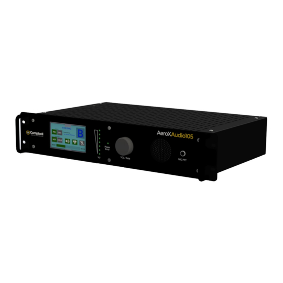
Summary of Contents for Campbell AeroX Audio 105
- Page 1 03/2023 Copyright © 2023 Campbell Scientific, Inc.
-
Page 2: Table Of Contents
Table of contents 1. Introduction 2. Precautions 3. Initial inspection 4. Specifications 4.1 Rear panel 4.2 Front panel 4.3 Microphone 5. Connector pin-outs 6. Product description 6.1 Power supply 6.2 Power-up process 6.3 VOL/DATA dial 6.4 PTT microphone 6.5 Audio outputs 6.6 Audio inputs 6.7 PTT connector 6.8 LIGHTS connector... -
Page 3: Introduction
1. Introduction The AeroX Audio105 is an audio controller that allows digital voice files to be transmitted over ground to air radios. Furthermore, it allows users to append audio messages to be transmitted through multiple audio inputs/outputs. Thus, the AeroX Audio105 fulfills the hardware component of an Automatic Terminal Information Service (ATIS) that produces critical flight safety information in the form of an audible voice information stream that can be transmitted over a radio for pilots. -
Page 4: Specifications
4. Specifications Case material: Aluminum Mount: 19 in (EIA-310) 2U rack mount Dimensions Front panel: 48.3 cm (19 in) width, 8.9 cm (3.5 in) height Case: 43.2 cm (17 in) width, 8.1 cm (3.2 in) height, 27.9 cm (11 in) depth Weight: 3.5 kg (7.7 lb) Power requirements: 80 to 264 VAC @ 25 W typical, 40 W maximum, 50/60 Hz 11 to 24 VDC @ 25 W typical, 40 W maximum Temperature: –20 to +70 °C... - Page 5 AUDIO IN: Female 3-pin XLR 600 ohm balanced Transformer isolated Separate 3.5 mm, 3-pole jack to the right of the XLR Adjustable audio level maximum: +4 dBu, 1.23 V rms, 1.74 V peak, 3.48 V peak-to-peak PTT (push-to-talk): 5x Volt free, break before make, normally open / closed relay contacts (contact rating 50 V @ 1 A), NOT protected against overload +5 VDC, 100 mA limited output used with relay contacts to...
-
Page 6: Front Panel
11-24VDC @ 25W, power input screw terminals: 40 W maximum, reverse polarity protected On/Off power switch Special features: HANDSET socket: Supports FAA handset with electret microphone including bias and speaker RJ11 VOICE MODEM socket: Telephone dial in voice modem RJ11 NOTE: Hand held microphone with PTT and audio Out CH1 cannot be used as they are used to support the FAA handset function. -
Page 7: Microphone
VU LEDs: Visual indication of selected monitor audio source 6x green LEDs and one red LED to show increasing audio level from lower LED up. For optimal performance the audio level should be high enough to light all the green LEDs but not the red LED, or at most only light the red LED occasionally. -
Page 8: Connector Pin-Outs
5. Connector pin-outs Table 5-1: AUDIO OUT, XLR male 3-pin terminals (CH1 to CH5) Description Schematic ground + audio – audio Shell ground Table 5-2: AUDIO OUT, 3.5 mm, 3-pole, jack Component Description Schematic Sleeve – audio Ring – audio + audio Table 5-3: AUDIO IN, XLR female 3-pin terminal Description... - Page 9 Table 5-5: PTT 25-pin, male, D connector Description Description Schematic PTT1 normally PTT1 common closed contact PTT1 normally ground open contact PTT2 normally PTT2 common closed contact PTT2 normally ground open contact PTT3 normally PTT3 common closed contact PTT3 normally ground open contact PTT4 normally...
- Page 10 Table 5-7: Redundant 9-pin, male D connector Description Description Schematic No connection No connection No connection No connection Redundant in No connection Redundant out No connection ground shell ground Table 5-8: Chassis main power inlet IEC C14 Description Schematic live phase neutral phase protective earth Table 5-9: 11-24VDC screw terminal strip...
- Page 11 Table 5-11: HANDSET socket: 4 Pin RJ11 6-4 Pin RJ12 Description Schematic (Black) microphone + (Red) speaker – (Green) speaker + (Yellow) microphone – Table 5-12: VOICE modem socket: 4 Pin RJ11 6-4 Pin RJ12 Description Schematic Ring line 1 Tip line 1 AeroX Audio105...
-
Page 12: Product Description
Initially, the POWER and VU LEDs illuminate. After 5 seconds, the AeroX Audio105 beeps and the LCD displays the Campbell Scientific logo. A solid POWER LED (not flashing) indicates the power-up process is complete and the AeroX Audio105 is fully operational. The final LCD screen should look similar to the following: 6.3 VOL/DATA dial... -
Page 13: Ptt Microphone
6.4 PTT microphone The PTT microphone allows the recording of messages directly into the AeroX Audio105. It is plugged into the 3.5 mm jack on the right side of the front panel. To operate, press the microphone button and hold while speaking into the microphone, then release the button when finished recording the message. -
Page 14: Audio Inputs
NOTE: The audio only transmits through one side of a stereo headphone. Connecting a headphone with an impedance of less than 300 ohms may cause reduced audio levels out of the XLR channel in which the headphone is connected. Maximum common mode voltage (pins 2 and 3) relative to ground is ±17 V. Ideally audio cables are screened. -
Page 15: Ptt Connector
6.7 PTT connector The rear panel includes a 25-pin, D plug that provides five PTT, volt-free, relay contacts that can be independently controlled to activate VHF radio transmitters or other devices. The relay contacts are rated at 50 VAC or DC at 1 A, but are NOT overload protected. Maximum voltage on any contact relative to ground is ±50 VAC or DC. - Page 16 An optically-isolated, auxiliary, digital input on this connector can be used with special software (contact factory for support). Maximum common mode voltage for pins 11 and 24 relative to ground is ±15 V. Input pins 11 and 24 are reverse polarity protected and is active if the voltage applied is greater than +3.5 V.
-
Page 17: Lights Connector
6.8 LIGHTS connector The LIGHTS connector is primarily used to turn on helicopter landing pad lights and is configured as a single, break-before-make, change-over, normally open, normally closed contact. Rated at 50 V at 1 A, this relay contact is NOT overload protected. Maximum voltage on any contact relative to ground is ±50 VAC or DC. -
Page 18: Redundant Connector
6.13 Redundant connector A redundant AeroX Audio105 rack module connects to this 9-pin D plug to support fault tolerance. For example: if two AeroX Audio105s are used for a single audio stream, the second box will act as a redundant audio box that can take over the audio if the first box fails or is powered down. -
Page 19: Micro-Controller Firmware Update Procedure
4. Rotate the Vol/Data dial to select "Restart". 5. Press the Vol/Data dial and confirm. 6. AeroX Audio105 will restart and copy files from the AudioServer\ directory and replace existing files on SBC. NOTE: The AeroX Audio105 update process will not replace files if their versions are the same. Therefore, the USB drive can be left in the USB port without any issues on the next start up. - Page 20 See Product Details on the Ordering Information pages at www.campbellsci.com . Other manufacturer's products, that are resold by Campbell Scientific, are warranted only to the limits extended by the original manufacturer. Refer to www.campbellsci.com/terms#warranty for more information.
- Page 21 To obtain a Returned Materials Authorization or Repair Reference number, contact your CAMPBELL SCIENTIFIC regional office. Please write the issued number clearly on the outside of the shipping container and ship as directed. For all returns, the customer must provide a “Statement of Product Cleanliness and Decontamination”...
- Page 22 Do not recharge, disassemble, heat above 100 °C (212 °F), solder directly to the cell, incinerate, or expose contents to water. Dispose of spent batteries properly. WHILE EVERY ATTEMPT IS MADE TO EMBODY THE HIGHEST DEGREE OF SAFETY IN ALL CAMPBELL SCIENTIFIC PRODUCTS, THE CUSTOMER ASSUMES ALL RISK FROM ANY INJURY RESULTING FROM IMPROPER INSTALLATION, USE, OR MAINTENANCE OF TRIPODS, TOWERS, OR...
- Page 23 Campbell Scientific Regional Offices Australia France Thailand Location: Garbutt, QLD Australia Location: Vincennes, France Location: Bangkok, Thailand Phone: 61.7.4401.7700 Phone: 0033.0.1.56.45.15.20 Phone: 66.2.719.3399 Email: info@campbellsci.com.au Email: info@campbellsci.fr Email: info@campbellsci.asia Website: www.campbellsci.com.au Website: www.campbellsci.fr Website: www.campbellsci.asia Brazil Germany Location: São Paulo, SP Brazil...
Need help?
Do you have a question about the AeroX Audio 105 and is the answer not in the manual?
Questions and answers