
Related Manuals for Campbell SDM-CAN


Summary of Contents for Campbell SDM-CAN
-
Page 1: User Guide
SDM-CAN CAN-Bus Interface User Guide Issued 26.6.07 © Copyright 2001-2007 Campbell Scientific Ltd. CSL 419... - Page 3 Guarantee This equipment is guaranteed against defects in materials and workmanship. This guarantee applies for twelve months from date of delivery. We will repair or replace products which prove to be defective during the guarantee period provided they are returned to us prepaid. The guarantee will not apply to: Equipment which has been modified or altered in any way without the written permission of Campbell Scientific...
-
Page 5: Table Of Contents
4.2.2 Simple CAN Data Transmission ... 4-3 4.2.3 Digital I/O Triggered CANbus Measurements ... 4-4 4.2.4 SlowSequence Instruction... 4-5 5.1 Connecting to the RS232 User Port... 5-1 5.2 Diagnostic Commands ... 5-1 5.3 Loading a New Operating System into the SDM-CAN Interface... 5-3... - Page 6 Appendix A. Principles of Operation ... A-1 A.1 Data Collection ...A-1 A.2 Frame Transmission...A-1 Appendix B. A Summary of Data Types ... B-1 Appendix C. Applications of the SDM-CAN on Networks Complying with the J1939 SAE Standards ... C-1 C.1 J1939 29-Bit Identifier Format ...C-1 C.2 J1939 11-Bit Identifier Format ...C-1...
-
Page 7: Section 1. Introduction
To use the SDM-CAN device it is assumed that you have a full working understanding of the CAN network you wish to monitor. While there are moves to standardise CAN networks for... -
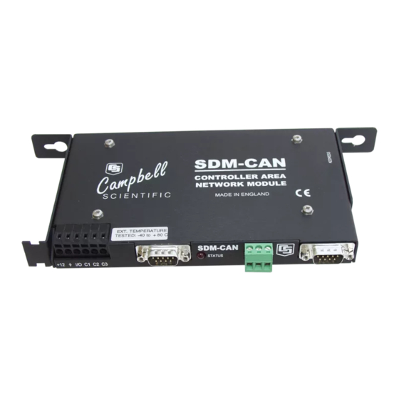
Page 8: Specifications
SDM-CAN CAN-Bus Interface User Guide other SDM-CAN interfaces) which might, for instance, be on other CAN-Bus networks in the same vehicle. In addition to connectors to the CAN network and the datalogger, an RS232 port is also provided both for diagnostics and operating system upgrades. -
Page 9: Power Consumption
1.2.2.1 Power Consumption • Typical active current in self-powered, isolated mode with the CAN-Bus in the recessive state: 70mA. (this is when the SDM-CAN is not transmitting). • Typical active current in self-powered, isolated mode with the CAN-Bus in the dominant state: 120mA (this is when data is being transmitted from the SDM-CAN device). -
Page 11: Section 2. Installation
Section 2. Installation The SDM-CAN can be mounted in a normal card slot of a CR9000 (using optional special end brackets), on a chassis plate (using the standard brackets supplied) or can be left free- standing. CR9000 and CR7 dataloggers require optional SDM connection kits and all dataloggers may require an upgrade to a version of operating system which supports the SDM-CAN interface. -
Page 12: Internal Jumper Settings
1) Decide whether the CAN network is already terminated, or if the SDM-CAN 2) Decide whether to operate the SDM-CAN in a mode where it is isolated from 3) If running in isolated mode decide whether the SDM-CAN will supply power 4) Decide whether the transmit functions of the SDM-CAN interface need to be Access to the jumpers requires the removal of the lid of the SDM-CAN. - Page 13 The default is for isolation enabled. Figure 2-1 SDM-CAN Internal Jumpers Figure 2-2 SDM-CAN Isolation enabled (default) Section 2. Installation Transmission of CAN data is hardware by default. To enable transmission,...
-
Page 14: Connection To The Datalogger And Power Supply
To allow communication between the SDM-CAN and a datalogger, firstly connect it to the datalogger’s SDM port, and then connect to a 12V power supply. Both the datalogger and the SDM-CAN 12V power supply must share a common ground. The SDM port is provided in different ways on different dataloggers: CR10X and CR23X –... -
Page 15: Led Status Indication
2.3.1 LED Status Indication When power is applied to the SDM-CAN the red ‘STATUS’ LED will flash to indicate the current status of the unit as a result of the power-up checks. -
Page 16: Led Status Indication
CAN Low and 0V ground reference. The 3 way screw terminal is marked as ‘G H L’ on the SDM-CAN case, where G=Ground, H=CAN High, L=CAN Low. The CIA, 9 pin, ‘D’ connector pin configuration is shown in Table 2-3. - Page 17 40 m and a maximum stub length of 0.3 m. These lengths increase significantly at lower bit rates. As discussed above you also need to consider: • If the SDM-CAN should terminate the network • If it should be configured in isolated mode •...
-
Page 19: Dataloggers To Use The Sdm-Can
SDM-CAN is enabled for transmission. The next common function is to read data back from the SDM-CAN, to decode it, and to store it in input locations once the program is running. A single entry of... -
Page 20: System Limitations
Firstly, as discussed above, when the datalogger compiles a program with P118 in it, it sends commands to the SDM-CAN instructing it what to do at run time. When it does this the SDM-CAN allocates some of its memory (a ‘bin’) for each call of P118 in the program. -
Page 21: The Datalogger Instruction
When transmitting CAN frames from the SDM-CAN there are situations where some frames are not transmitted. This is because the SDM-CAN has a two layer buffer for transmitted frames. This allows a frame to be transmitted whilst a new frame is being built. - Page 22 SDM-CAN CAN-Bus Interface User Guide Instruction 118: SDM-CAN PARAM. NUMBER DATA TYPE SDM Address (Parameter 01:) This parameter should match the SDM address set by the address switch on the side of the module to which this instruction applies. Please see section 2.1, above, for more details.
- Page 23 These are determined by the characteristics of the network and other devices on the network. The total of these two time segments determines the time when the SDM-CAN samples the data bit and is known as t segment is known as phase segment two or t...
- Page 24 (see Appendix C for a discussion of this standard and use with the SDM-CAN). The SDM-CAN is, however, transparent to any special meaning of the ID; each packet is only referenced by the full ID. The CAN 2.0A standard uses an ID with 11 bits, while CAN 2.0B uses 29 bits.
- Page 25 Value Build a data frame for transmission: The data will be sent to the SDM-CAN where it is written into a working 8-byte buffer in memory. The data is written starting at the bit position determined by parameter 09 and the number of bits stored by parameter 10. When the data type parameter is set in the range of 7..12, the data is written to the buffer directly,...
- Page 26 This range of parameter values instructs the datalogger to send a data value to the SDM-CAN in the format specified; it is loaded into the specified point in a data frame and then immediately transmitted onto the CAN-Bus. Bits within the data frame that are not set are left at zero.
- Page 27 Set-up previously built data frame as a Remote Frame Response (type 26): When parameter 08 is set to 26, P118 will configure the SDM-CAN to use a previously ‘built’ data frame as remote frame response for packets of the specified ID.
- Page 28 Read the signature and version number of the SDM-CAN operating system (type 30): This will return the OS signature and the OS Version number in separate locations. If the SDM-CAN detects that the OS signature is bad then zero will be returned.
- Page 29 SDM-CAN returns the last value captured from the network, even if read before (Default) SDM-CAN returns –99999 if a data value is requested by the datalogger and a new value has not been captured from the network, since the last request.
- Page 30 SDM-CAN supports both methods of referencing the start point. By default the SDM-CAN follows the ISO standard and the LSB is referenced to the right-most bit of the frame. The bit number can range from 1 to 64 as there are up to 64 bits in a CAN frame.
-
Page 31: Advanced Programming Techniques
The main problem is that the interrupt function might run more time stamps to the faster measurements in order to allow normal data analysis. To enable the interrupt facility on the SDM-CAN you need to index (--) the program on the number-of-bits parameter (10) of the particular P118 instruction that you want to cause the interrupt when data is received. - Page 32 50 milliseconds following the end of one interrupt before the SDM-CAN will raise the port for another interrupt. This could be a limitation in high speed data capture applications, hence the need for switch 2.
-
Page 33: Group Trigger
This mode is enabled when an SDM-Group Trigger (P110) instruction is encountered. When this instruction runs, it broadcasts a special SDM message which causes all the SDM-CAN devices to copy the last data values captured from the CAN-bus into the working data buffers, and no further updates are allowed until P110 runs again (normally at the next execution of the program table). - Page 34 Transfer a CAN frame from the buffer to the working buffer using an SDN-CAN instruction with data type 33. Parse the CAN data frame using the normal SDM-CAN data types 1-6. Repeat from (3) until you have collected and parsed all the CAN frames you require from the buffer.
-
Page 35: Program Examples
The above example uses the J1939 standard to define the ID parameter and value position in the data frame. Please refer to Appendix C for an explanation of the application of the SDM-CAN interface to networks complying to the J1939 standard. -
Page 36: Simple Can Data Transmission
The following example transmits a 16 bit temperature value to a CAN network running at 500K baud. ;{CR10X} *Table 1 Program 01: 1 ;When Flag 1 is high set SDM-CAN switches to transmit mode 1: 11 2: 30 ;Load input location with value for switches ;Send switch settings to SDM-CAN ;Set flag 1 low after sending switch settings... -
Page 37: Building And Sending Data Frames
*Table 3 Subroutines End Program NOTE The default setting for the SDM-CAN internal software switches is 0. The switches must be set by using the data type 32 parameter to enable data transmission. Also remember to check the jumper settings inside the SDM-CAN if enabling transmission, as the default setting is for transmission to be disabled in hardware. -
Page 38: Using The Interrupt Function
By indexing (‘--‘) the No. of bits parameter, when a new value that an instruction refers to is received the SDM-CAN I/O interrupt is enabled. This can be used to set a control port high and run an interrupt subroutine. An example of using the interrupt function is shown below. -
Page 39: Using The Group Trigger
For the SDM-CAN, this instruction is can be used in a vehicle where more than one CANbus network is present. An example of using the group trigger is shown below. - Page 40 SDM-CAN CAN-Bus Interface User Guide 7: 7 8: 23 9: 1 10: 32 11: 1 12: 1 13: 1.0 14: 0.0 ;Retrieve Data from CAN network B 1: 01 2: 4 3: 5 4: 2 5: 1024 6: 7680 7: 12...
-
Page 41: Section 4. Programming Crbasic Dataloggers To Use The Sdm-Can
CR9000 and CR5000 to allow users to run a program at more than 200Hz with the SDM-CAN. It gives a 5 fold improvement in performance over normal mode. Block mode operation is activated by using data types 65 to 70;... -
Page 42: Datalogger Instruction
4.2 Datalogger Instruction The SDM-CAN is controlled by an instruction called CANBUS. Please check that your datalogger’s operating system includes this instruction. You may also require an update to your CRBASIC editor to get the full help screens. Contact Campbell Scientific if you need advice about upgrading your operating system. -
Page 43: Reading Can Data
Section 4. Programming the CR9000 and CR5000 'Scan interval number 'Scan interval units (Secs) ')Set SDM-CAN to 250K ')Network speed 'Repetitions 'SDM address of SDM-CAN Module 'Collect and retrieve data values 'Start position in data frame 'Number of bits/value 'Number of values 'Multiplier... -
Page 44: Simple Can Data Transmission
SDM-CAN CAN-Bus Interface User Guide 4.2.2 Simple CAN Data Transmission The following example transmits a 16 bit temperature value to a CAN network running at 250K baud. 'Set scan rate Const PERIOD = 1 Const P_UNITS = 2 \\\\\\\\\\\\\\\\\\\\ THERMOCOUPLE CONSTANTS ////////////////////... -
Page 45: Digital I/O Triggered Canbus Measurements
CR10X, CR7 and CR23X it is possible to connect the I/O line from the SDM-CAN to a Digital I/O port. A program control instruction can then be used to trigger the retrieval of new CAN data from the SDM-CAN when the port is high. An example of this is shown below... -
Page 46: Slowsequence Instruction
SDM-CAN CAN-Bus Interface User Guide '\\\\\\\\\\\\\\\\\\\\\\\\\ CANBUS CONSTANTS ////////////////////// '------------------- Physical Network Parameters ----------------- Const TQUANTA = 4 Const TSEG1 = 5 Const TSEG2 = 2 '---------------------- Data Frame Parameters -------------------- '___________________________CANbus Block1_________________________ Const CANREP1 = 1 Const ADDRESS1 = 0... -
Page 47: Section 5. Using The Rs232 Serial Diagnostics Port
As soon as your baud rate has been detected, the SDM-CAN will return the prompt ‘CAN>’ to your terminal window. If you have just powered the SDM-CAN up, you must wait until the LED status flash has finished before you attempt to communicate. - Page 48 As soon as the baud rate is found, the bus parameters TQUANTA, TESG1, TSEG2 and frames / n*50msec are reported to the user. The SDM-CAN will then be set to, and stay at, this baud rate until the changed by the datalogger following a re-compilation of the program by the user, or by a datalogger SDM communications error which will force the SDM-CAN to be reset.
-
Page 49: Loading A New Operating System Into The Sdm-Can Interface
96. SWITCH nnnn – This command changes the internal switch settings of the SDM-CAN. Please refer to Data type 32, in section 3 above, for details of the switch parameter. VERBOSE nnnn – The parameter nnnn is the verbose mode. With no parameter or when nnnn=0 verbose mode is off, otherwise if nnnn>0 verbose mode is on. - Page 50 For downloading software you will need the following: • • • • The SDM-CAN also requires a 12V power supply, but does not have to be connected to a datalogger. To load the new operating system take the following steps: • •...
-
Page 51: Appendix A. Principles Of Operation
When the datalogger program reaches a point where it needs to read the data, the SDM-CAN will first check the ‘New data flag’. If this flag is clear, the datalogger will read the previous data value unless the switch is set to detect/prevent multiple reads (see section 3) in which case an over-range value is read (-99999 on some dataloggers). - Page 52 CAN-Bus or set it up as a Remote Frame Response. For the transmitted frames, the SDM-CAN will set a flag in the buffer to indicate new data is ready for transmission. The SDM-CAN will scan the buffers, checking this flag in each buffer that is set for transmission.
-
Page 53: Appendix B. A Summary Of Data Types
Appendix B. A Summary of Data Types A summary table of the data types is given below for quick reference. Data Type Description Retrieve data; unsigned integer, MSB first Retrieve data; unsigned integer, LSB first Retrieve data; signed integer, MSB first Retrieve data;... - Page 54 0002 The SDM-CAN is not involved in bus activities; error counters < 96. 0003 The SDM-CAN is not involved in bus activities; at least one error counter >=96. Read SDM-CAN operating system and version number Send Remote Frame Request. Set SDM-CAN's internal switches...
-
Page 55: C-1 Mapping Of The J1939 Fields Into A 29-Bit Identifier
SDM-CAN on Networks Complying with the J1939 SAE Standards. This Appendix describes the use of the SDM-CAN in applications where the CAN network complies to the J1939 standard, which is common in truck, bus and marine applications in the USA. This appendix is not intended to act as a full reference to those standards, but to simply describe the coding of the ID parameter and to give examples of how to decode some of the common, defined J1939 data packets. -
Page 56: C.4 Retrieving J1939 Accelerator Pedal Position Data Using A Cr9000/Cr5000 (Bus Speed 250K Baud)
SDM-CAN CAN-Bus Interface User Guide C.3 J1939 Data Frame Format The Data Frame consists of 8 bytes with byte one at the left side of the frame and byte eight at the right side. Within each byte, bit 8, the most significant bit is at the left side of the byte. -
Page 57: C-4 Mapping Of J1939 Identifier Field Values Into A 29-Bit Identifier
Const ADDRESS1 = 0 Const DATATYPE1 = 2 Const STARTBIT1 = 49 Const NUMBITS1 = 8 Const NUMVALS1 = 1 Dim CANBlk1(CANREP1) Appendix C. Using SDM-CAN on J1939 Networks and used as the ID parameter. 87654321 87654321 87654321 'Scan interval number... -
Page 58: C.5 Retrieving J1939 Accelerator Pedal Position Data Using A Cr23X/Cr10X (Bus Speed 250K Baud)
SDM-CAN CAN-Bus Interface User Guide '\\\\\\\\\\\\\\\\\\ ALIASES & OTHER VARIABLES ////////////////// Alias CANBlk1(1) = Accel_Pedal '\\\\\\\\\\\\\\\\\\\\\\\\\\\ PROGRAM /////////////////////////// BeginProg 'MainSequence Scan(PERIOD,P_UNITS,0,0) '__________________________ CAN Blocks __________________________ 'Retrieve Accelerator pedal position Data from CAN network CanBus(CANBlk1(),ADDRESS1,TQUANTA,TSEG1,TSEG2,217056000, DATATYPE1,STARTBIT1,NUMBITS1,NUMVALS1,0.4,0) Next Scan EndProg NOTE Due to current system constraints the ID parameter must be entered directly into the CanBus instruction. -
Page 59: C-6 Mapping Of J1939 Identifier Field Values Into A 29-Bit Identifier
5: 768 6: 7680 7: 12 8: 2 9: 49 10: 8 11: 1 12: 7 Appendix C. Using SDM-CAN on J1939 Networks and used as the second ID parameter. 87654321 87654321 87654321 Execution Interval (seconds) SDM Address Time Quanta... - Page 60 SDM-CAN CAN-Bus Interface User Guide 13: 0.125 14: 0.0 *Table 2 Program 02: 0.0000 *Table 3 Subroutines End Program Mult Offset Execution Interval (seconds)
-
Page 61: Appendix D. Examples Of Can Data Frames And Data Encoding And Decoding
Decoding This Appendix gives examples of typical CAN data frames with worked examples of how to encode or decode such data using the SDM-CAN. Bits are Transmitted (Txed) or Received (Rxed) starting from the left of the data frame. Txed/Rxed first... - Page 62 SDM-CAN CAN-Bus Interface User Guide Start bit (parameter 09:) Right Hand reference. 1: 0 2: 1 3: 5 4: 2 5: 1000 6: 0000 7: 00 8: 2 9: 9 10: 16 11: 1 12: 1 13: 1.0 14: 0.0 Start bit (parameter 09:) Left Hand reference.
- Page 63 Start bit (parameter 09:) Right Hand reference. SDM-CAN (P118) 1: 0 2: 1 3: 5 4: 2 5: 1000 6: 0000 7: 00 8: 2 9: 9 10: 16 11: 2 12: 1 13: 1.0 14: 0.0 Start bit (parameter 09:) Left Hand reference.
- Page 64 SDM-CAN CAN-Bus Interface User Guide Start bit (parameter 09:) Right Hand reference. 1: 0 2: 1 3: 5 4: 2 5: 1000 6: 0000 7: 00 8: 2 9: 13 10: 12 11: 2 12: 1 13: 1.0 14: 0.0 Start bit (parameter 09:) Left Hand reference.
- Page 65 Start bit (parameter 09:) Right Hand reference. SDM-CAN (P118) 1: 0 2: 1 3: 5 4: 2 5: 1000 6: 0000 7: 00 8: 4 9: 13 10: 12 11: 1 12: 1 13: 1.0 14: 0.0 Start bit (parameter 09:) Left Hand reference.
- Page 66 SDM-CAN CAN-Bus Interface User Guide Start bit (parameter 09:) Right Hand reference. 1: 0 2: 1 3: 5 4: 2 5: 1000 6: 0000 7: 00 8: 6 9: 25 10: 32 11: 1 12: 1 13: 1.0 14: 0.0 Start bit (parameter 09:) Left Hand reference.
- Page 67 Start bit (parameter 09:) Right Hand reference. SDM-CAN (P118) 1: 0 2: 1 3: 5 4: 2 5: 1000 6: 0000 7: 00 8: 1 9: 1 10: 16 11: 1 12: 1 13: 1.0 14: 0.0 Start bit (parameter 09:) Left Hand reference.
- Page 68 SDM-CAN CAN-Bus Interface User Guide Start bit (parameter 09:) Right Hand reference. 1: 0 2: 1 3: 5 4: 2 5: 1000 6: 0000 7: 00 8: 3 9: 1 10: 16 11: 2 12: 1 13: 1.0 14: 0.0 Start bit (parameter 09:) Left Hand reference.
- Page 69 Start bit (parameter 09:) Right Hand reference. SDM-CAN (P118) 1: 0 SDM Address 2: 1 Time-quanta 3: 5 Tseg1 4: 2 Tseg2 5: 1000 ID Bits 0..10 6: 0000 ID Bits 11..23 7: 00 ID Bits 24..28 8: 1 Rx, unsigned int, MSB 1st 9: 1 Start Bit No.
- Page 70 SDM-CAN CAN-Bus Interface User Guide Start bit (parameter 09:) Right Hand reference. 1: 0 2: 1 3: 5 4: 2 5: 1000 6: 0000 7: 00 8: 1 9: 1 10: 12 11: 1 12: 1 13: 1.0 14: 0.0 Start bit (parameter 09:) Left Hand reference.
- Page 71 Appendix D. Examples of Encoding & Decoding Start bit (parameter 09:) Right Hand reference. SDM-CAN (P118) 1: 0 SDM Address 2: 1 Time-quanta 3: 5 Tseg1 4: 2 Tseg2 5: 1000 ID Bits 0..10 6: 0000 ID Bits 11..23 7: 00 ID Bits 24..28...
- Page 74 CAMPBELL SCIENTIFIC COMPANIES Campbell Scientific Africa Pty. Ltd. (CSAf) Campbell Scientific Australia Pty. Ltd. (CSA) Campbell Scientific do Brazil Ltda. (CSB) CEP: 005543-000 São Paulo SP BRAZIL Campbell Scientific Canada Corp. (CSC) Campbell Scientific Ltd. (Germany) Fahrenheitstrasse13, D-28359 Bremen Please visit www.campbellsci.com to obtain contact information for your local US or International representative. Campbell Scientific, Inc.
Need help?
Do you have a question about the SDM-CAN and is the answer not in the manual?
Questions and answers