
Related Manuals for Campbell CM3


Summary of Contents for Campbell CM3
- Page 1 CM3 Pyranometer Revision: 10/02 C o p y r i g h t ( c ) 1 9 9 9 - 2 0 0 2 C a m p b e l l S c i e n t i f i c ,...
- Page 2 CAMPBELL SCIENTIFIC, INC. CAMPBELL SCIENTIFIC, INC. will return such products by surface carrier prepaid. This warranty shall not apply to any CAMPBELL SCIENTIFIC, INC. products which have been subjected to modification, misuse, neglect, accidents of nature, or shipping damage. This warranty is in lieu of all other warranties, expressed or implied, including warranties of merchantability or fitness for a particular purpose.
-
Page 3: Table Of Contents
CM3 Pyranometer Table of Contents PDF viewers note: These page numbers refer to the printed version of this document. Use the Adobe Acrobat® bookmarks tab for links to specific sections. 1. General Description............1 2. Specifications .............1 3. Installation..............2 4. Wiring ................4 5. - Page 4 This is a blank page.
-
Page 5: General Description
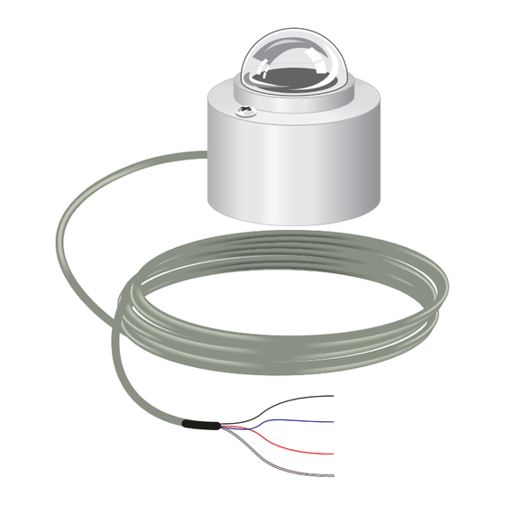
This manual provides information for interfacing Kipp & Zonen’s CM3 Pyranometer to a CR10(X), CR510, CR23X, CR7 or 21X datalogger. The CM3 is shipped with an instruction manual provided by Kipp & Zonen that contains information concerning the CM3’s construction, spectral sensitivity, cosine response, and a simple sensor check out procedure. -
Page 6: Installation
CM3MT: 0.6 lbs / 3 lbs 3. Installation The CM3 should be mounted such that it is never shaded by the tripod/tower or other sensors. To ensure accurate measurements, the CM3 should be mounted using the CM3MT base/leveling fixture or equivalent. The CM3MT incorporates a bubble level and three adjustment screws. -
Page 7: Cm3 And Cm3Mt
PN7790(3) 015 Pyranometer Mounting Arm or 025 Pyranometer Crossarm Stand FIGURE 3-1. CM3 and CM3MT Install the CM3MT Mount on either the 025 Pyranometer Cross Arm Stand, the 015 Pyranometer Mounting Arm, or the UTKZ (not yet available, please call) before mounting them to the tower or tripod. -
Page 8: Utkz Leveling Fixture And Crossarm Mount And Ut018 Tower Mounting Bracket And Crossarm
(AG) and the clear to ground (G). On the CR23X, 21X or CR7 both the white and clear leads are connected to ground ( While a differential measurement is better and preferred, the CM3 can be measured on a single-ended channel using Instruction 1 if the power induced... -
Page 9: Cm3 Wiring
CM3 Pyranometer If a 21X is used to measure the CM3 and it powers a 12 VDC sensor or 12 VDC radio, the current drawn off the 12 VDC supply may cause a difference in ground potential between the 21X ground terminals and the reference ground point in the datalogger. -
Page 10: Example Programs
V / W m t = datalogger execution interval in seconds 5.1 Average Solar Radiation Example 1 shows the program instructions used by a CR10X to measure the signal from the CM3. A sixty-minute average is calculated and stored in final storage. -
Page 11: Total Solar Radiation
CM3 Pyranometer Example 1 ;{CR10X} *Table 1 Program 01: 10 Execution Interval (seconds) 1: Volt (Diff) (P2) 1: 1 Reps 2: 24 250 mV 60 Hz Rejection Range 3: 1 DIFF Channel 4: 1 Loc [ W_m2 5: 45.725 Mult ;multiplier = (1 / 0.02187 mV / W/m2) 6: 0.0... -
Page 12: Output Format Considerations
CM3 Pyranometer 5.2.1 Output Format Considerations If the solar radiation is totalized in units of kJ m , there is a possibility of over-ranging the output limits. The largest number that the datalogger can output to final storage is 6999 in low resolution and 99999 in high resolution (Instruction 78, Set Resolution). - Page 13 Another method would be to send the sensor to a facility that has a “secondary standard”. Contact Kipp & Zonen (www.kippzonen.com) for the nearest calibration facility, or send it to Campbell Scientific and they will have it recalibrated.
- Page 14 CM3 Pyranometer This is a blank page.
- Page 15 This is a blank page.
- Page 16 Campbell Scientific Companies Campbell Scientific, Inc. (CSI) 815 West 1800 North Logan, Utah 84321 UNITED STATES www.campbellsci.com info@campbellsci.com Campbell Scientific Africa Pty. Ltd. (CSAf) PO Box 2450 Somerset West 7129 SOUTH AFRICA www.csafrica.co.za sales@csafrica.co.za Campbell Scientific Australia Pty. Ltd. (CSA)
Need help?
Do you have a question about the CM3 and is the answer not in the manual?
Questions and answers