
Related Manuals for Campbell CMP6


Summary of Contents for Campbell CMP6
- Page 1 CMP6, CMP10, CMP11, CMP21 Pyranometers Revision: 9/19 Copyright © 2006 – 2019 Campbell Scientific, Inc.
- Page 2 Limited Warranty “Products manufactured by CSI are warranted by CSI to be free from defects in materials and workmanship under normal use and service for twelve months from the date of shipment unless otherwise specified in the corresponding product manual. (Product manuals are available for review online at www.campbellsci.com.) Products not manufactured by CSI, but that are resold by CSI, are warranted only to the limits extended by the original manufacturer.
- Page 3 Campbell Scientific company serves your country. To obtain a Returned Materials Authorization (RMA) number, contact CAMPBELL SCIENTIFIC, INC., phone (435) 227-9000. Please write the issued RMA number clearly on the outside of the shipping container. Campbell Scientific’s shipping address is: CAMPBELL SCIENTIFIC, INC.
- Page 4 Periodically (at least yearly) check electrical ground connections. • WHILE EVERY ATTEMPT IS MADE TO EMBODY THE HIGHEST DEGREE OF SAFETY IN ALL CAMPBELL SCIENTIFIC PRODUCTS, THE CUSTOMER ASSUMES ALL RISK FROM ANY INJURY RESULTING FROM IMPROPER INSTALLATION, USE, OR MAINTENANCE OF TRIPODS, TOWERS, OR ATTACHMENTS TO TRIPODS AND TOWERS SUCH AS SENSORS, CROSSARMS, ENCLOSURES, ANTENNAS, ETC.
-
Page 5: Table Of Contents
Recalibration ..................17 Troubleshooting ................. 17 Appendices A. Importing Short Cut Code Into CRBasic Editor ... A-1 B. Example Programs ..........B-1 Example Program for Measuring a CMP6 ........B-1 Example Program for Measuring a CMP10 or CMP11 ....B-2... - Page 6 5-1. Model Comparison ................4 6-1. CMP-series Specifications ..............6 7-1. CMP6, CMP10, and CMP11 Wire Color, Function, and Data Logger Connection ................. 12 7-2. CMP21 Wire Color, Function, and Data Logger Connection .... 12 7-3. Multipliers Required for Flux Density and Total Fluxes ....14 B-1.
- Page 7 Table of Contents CRBasic Examples B-1. CR1000X Example Program for Measuring a CMP6 ...... B-1 B-2. CR1000X Example Program for Measuring a CMP10 or CMP11 .. B-2 B-3. CR1000X Example Program for Measuring a CMP21 ....B-3 C-1. CVF4 Example Program ..............C-10...
-
Page 8: Introduction
These pyranometers are rugged, but they should be handled as precision scientific instruments. • Care should be taken when opening the shipping package to not damage or cut the cable jacket. If damage to the cable is suspected, contact Campbell Scientific. • Pyranometers purchased from Campbell Scientific have different wiring than pyranometers purchased directly from Kipp &... -
Page 9: Calibration Certificate
CMP6, CMP10, CMP11, and CMP21 Pyranometers Calibration Certificate Each pyranometer is shipped with an instruction manual provided by Kipp & Zonen that contains information concerning its construction, spectral sensitivity, cosine response, and a simple sensor check out procedure. Included with the sensor and manual is a calibration certificate with the sensor sensitivity value and serial number. - Page 10 CMP6, CMP10, CMP11, and CMP21 Pyranometers Repeat step three for other sensors. In Output Setup, type the scan rate, meaningful table names, and the Data Output Storage Interval.
-
Page 11: Overview
CMP6, CMP10, CMP11, and CMP21 Pyranometers Select the measurement and its associated output options. Click Finish and save the program. Send the program to the data logger if the data logger is connected to the computer. If the sensor is connected to the data logger, check the output of the sensor in the data display in LoggerNet, PC400, RTDAQ, or PC200W to make sure it is making reasonable measurements. -
Page 12: Specifications
• Provides measurements in direct sunlight, under plant canopies, when the sky is cloudy, and in artificial light Compatible with Campbell Scientific CRBasic data loggers: CR300 • series, CR6 series, CR800 series, CR1000, CR1000X, CR3000, CR5000, and CR9000(X) -
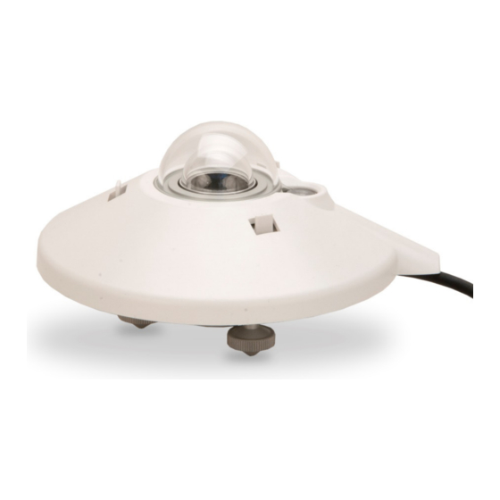
Page 13: Cvf4 Ventilation Unit
CMP6, CMP10, CMP11, and CMP21 Pyranometers TABLE 6-1. CMP-series Specifications Specification CMP6 CMP10/CMP11 CMP21 ISO Classification First Class Secondary Standard Maximum irradiance 2000 W•m –2 4000 W•m –2 Spectral range 285 to 2800 nm (50% points) Response time (95 %) <18 s... -
Page 14: Installation
CMP6, CMP10, CMP11, and CMP21 Pyranometers Heating power: 5.5 W Heater induced offset: <1 W•m –2 (with CMP10/CMP11 pyranometer) Weight without cable: 1.6 kg (3.5 lb) Height: 12.95 cm (5.1 in) Length: 35.5 cm (14.0 in) Width: 23.0 cm (9.1 in) -
Page 15: Pyranometer Installation
CMP6, CMP10, CMP11, and CMP21 Pyranometers FIGURE 7-1. Pyranometer installation CM2XX-Series Crossarm FIGURE 7-2. Pyranometer mounted horizontally for the Northern Hemisphere (left) and Southern Hemisphere (right) -
Page 16: Two Views Of A Pyranometer Mounted At An Angle For The Northern
CMP6, CMP10, CMP11, and CMP21 Pyranometers FIGURE 7-3. Two views of a pyranometer mounted at an angle for the Northern Hemisphere FIGURE 7-4. Pyranometer mounted at an angle for the Southern Hemisphere... -
Page 17: Mounting To A Tripod Or Tower
CMP6, CMP10, CMP11, and CMP21 Pyranometers Mounting to a Tripod or Tower Tools required for installation on a tripod or tower: 4 mm (5/32-inch) Allen wrench 8 mm (5/16-inch) open-end wrench for U-bolt nuts Tape measure UV-resistant wire ties Side-cut pliers... -
Page 18: Wiring
Blue Black Shield FIGURE 7-6. Thermopile detector schematic Connections to Campbell Scientific data loggers are given in TABLE (CMP6, CMP10, and CMP11) and TABLE (CMP21). Solar radiation can be measured by using either differential or single-ended analog terminals. The differential measurement has better noise rejection and is therefore recommended. -
Page 19: Cmp6, Cmp10, And Cmp11 Wire Color, Function, And Data Logger Connection
CMP6, CMP10, CMP11, and CMP21 Pyranometers TABLE 7-1. CMP6, CMP10, and CMP11 Wire Color, Function, and Data Logger Connection Differential Single-Ended Wire Wire Data Logger Data Logger Color Function Connection Terminal Connection Terminal U configured for U configured for single-... -
Page 20: Programming
CMP6, CMP10, CMP11, and CMP21 Pyranometers Programming Short Cut is the best source for up-to-date data logger programming code. If data acquisition requirements are simple, you can probably create and maintain a data logger program exclusively with Short Cut. If your data... -
Page 21: Multiplier
CMP6, CMP10, CMP11, and CMP21 Pyranometers Select the input range as follows: 1. Estimate the maximum expected input voltage by multiplying the maximum expected irradiance (in W•m –2 ) by the calibration factor (in µV / W•m –2 ). Divide the answer by 1000 to give the maximum in millivolt units. -
Page 22: Output Format Considerations
(FIGURE 8-1). The drying cartridge in the CMP6, CMP11, and CMP21 have orange and • opaque desiccant granules (Section 8.1.1, Changing the Desiccant (p. -
Page 23: Changing The Desiccant
The CMP10 has an internal drying cartridge that will last for at least ten years if the housing is not opened. This significantly minimizes maintenance. The drying cartridge of the CMP6, CMP11, and CMP21 uses desiccant that needs to be periodically replaced. The silica gel desiccant granules in the drying cartridge should be orange and opaque. -
Page 24: Check Sensor Output
The calibration of the pyranometer may drift with time and exposure to radiation. Campbell Scientific recommends recalibrating every two years. The sensor should be returned to Campbell Scientific for recalibration. Refer to the Assistance page for information on returning the pyranometer to Campbell Scientific for recalibration. -
Page 25: Importing Short Cut Code Into Crbasic Editor
Appendix A. Importing Short Cut Code Into CRBasic Editor Short Cut creates a .DEF file that contains wiring information and a program file that can be imported into the CRBasic Editor. By default, these files reside in the C:\campbellsci\SCWin folder. Import Short Cut program file and wiring information into CRBasic Editor: Create the Short Cut program following the procedure in Section 4, . -
Page 26: Example Programs
(1,Batt_Volt,FP2,0,False) Sample (1,PTemp,FP2) Average (1,CMP6_Irr,IEEE4,False) StdDev (1,CMP6_Irr,IEEE4,False) EndTable BeginProg Scan (1,Sec,0,0) 'Measure the Battery Voltage and Panel Temperature PanelTemp (PTemp,60) Battery (Batt_Volt) 'Measure the CMP6. Multiplier (M) = 1000/c where c = 14.33. VoltDiff (CMP6_Irr,1,mV200C,1,True ,10000,60,1000/14.33,0) CallTable TenMin NextScan EndProg... -
Page 27: Example Program For Measuring A Cmp10 Or Cmp11
Appendix B. Example Programs B.2 Example Program for Measuring a CMP10 or CMP11 Although this example is for the CR1000X, other CRBasic data loggers are programmed similarly. The following program measures the CMP11 every second and converts the millivolt output to W•m . -
Page 28: Example Program For Measuring A Cmp21
Appendix B. Example Programs B.3 Example Program for Measuring a CMP21 Although this example is for the CR1000X, other CRBasic data loggers are programmed similarly. The following program measures the CMP21 every second. It converts the pyranometer millivolt output to W•m . - Page 29 Appendix B. Example Programs 'Measure the Battery Voltage and Panel Temperature PanelTemp (PTemp,60) Battery (Batt_Volt) 'Measure the CMP21 pyranometer. Multiplier (M) = 1000/c where c = 8.65. VoltDiff (CMP21_Irr,1,mV200C,3,True,10000,60,1000/8.65,0) 'CMP21 Thermistor Measurement BrHalf (Vs_Vx,1,mV5000,15,Vx1,1,2500,True ,0,250,1.0,0) Rs = 1000*(Vs_Vx/(1-Vs_Vx)) CMP21_T_C = 1/(1.0295e-3+2.391e-4*LN(Rs)+1.568e-7*(LN(Rs))^3)-273.15 'Convert CMP21 temp to Kelvin.
-
Page 30: Cvf4 Ventilation Unit
The CVF4 is meant to run continuously. The heater can either be powered on continuously for cold regions or be switched on by a Campbell Scientific data logger to remove dew in the morning and be switched off afterwards. In that case, the heater could operate for a period of time before and after sunrise. -
Page 31: Cvf4 Components (Top View, No Cover
Appendix C. CVF4 Ventilation Unit Pyranometer Cover Nut Mounting Holes Heater Ventilator Heater Pyranometer CVF4 Cable Cover Nut Cable Slot Connector FIGURE C-1. CVF4 Components (top view, no cover) Connector Box Mounting Feet Filter Cover Mounting Feet Cover Nut FIGURE C-2. CVF4 Components (bottom view) -
Page 32: Cvf4 Installation
Appendix C. CVF4 Ventilation Unit FIGURE C-3. CVF4 Ventilation Unit and Ships With Kit C.3 CVF4 Installation Siting information provided in Section 7.1, Siting , is pertinent when using (p. 7) the CVF4 heater/ventilation. CVF4 heater/ventilator unit includes the heater/ventilator unit, white cover, cable, and mounting hardware. -
Page 33: Crossarm And Nu-Rail Crossover Fitting Mounted To Mast (Exploded View
Appendix C. CVF4 Ventilation Unit To install, do the following: Mount the crossarm to the tripod or tower (FIGURE C-4). U-bolt Washers CM210 Bracket (included with crossarm) U-bolt Nuts Nu-Rail Crossover Fitting U-bolts CM200-series Crossarm FIGURE C-4. Crossarm and Nu-Rail Crossover Fitting Mounted to Mast (exploded view) Attach the CM220 Right-Angle Mounting Bracket (FIGURE C-5) or a 1-inch-by-1-inch Nu-Rail Crossover Fitting (FIGURE C-4) to the... - Page 34 Appendix C. CVF4 Ventilation Unit 3. Place the CVF4 (without the white plastic cover) on the CVF4 Mounting Stand with the fan hanging over the edge of the plate and with the mounting feet lined up with the mounting holes. Fasten the CVF4 feet to the mounting stand by using the supplied washers and screws (FIGURE C-6).
-
Page 35: Cvf4 Mounted To Cvf4 Mounting Stand (Pyranometer Not Shown
Appendix C. CVF4 Ventilation Unit Turn the pyranometer leveling screws as required to bring the bubble of the level within the ring. Tighten the pyranometer mounting screws to secure the assembly in its final position. Check that the pyranometer is still correctly leveled and adjust as necessary. -
Page 36: Wiring
Appendix C. CVF4 Ventilation Unit C.4 Wiring Wiring of the CVF4 is shown in TABLE and TABLE C-2. Refer to Section 7.3, Wiring , for information about wiring the pyranometer. (p. 11) TABLE C-1. CVF4 8-Pin Wiring Wire Power Supply Color Description Connection... -
Page 37: Schematics
Appendix C. CVF4 Ventilation Unit C.4.1 Schematics FIGURE C-9. 8-Pin Schematic... -
Page 38: Cvf4 Example Program
Appendix C. CVF4 Ventilation Unit FIGURE C-10. 4-Pin Schematic C.5 CVF4 Example Program In the example program, the CVF4 heater is controlled based on the solar position. The109 temperature sensor provides the temperature measurement used in the solar position instruction. The CVF4 fan is continuously on. Power to the CVF4 heater is switched using one SPST Single-Channel Solid-State Relay (FIGURE C-10). - Page 39 Appendix C. CVF4 Ventilation Unit TABLE C-3. Wiring for Program Controlling CVF4 Heater CMP11 CVF4 Power Wire Wire Wire Supply CR1000X Function Color Color Color Relay Terminal Terminal ⏚ 109 Shield Shield CVF4 Ventilator Power CVF4 Heater Power White CVF4 Power Ground Black CVF4 Tachometer Signal Green...
-
Page 40: Cvf4 Heater/Ventilator Maintenance
Appendix C. CVF4 Ventilation Unit 'Main Program BeginProg Scan (1,Sec,0,0) PanelTemp (PTemp,60) 'Measure wire panel temperature Battery (batt_volt) 'Measure battery voltage 'Retrieve the current time for use in the Solar Position Calculation '--------------------------------------------------------------------------- RealTime (TimeArray()) '--------------------------------------------------------------------------- 'Measure Air Temperature '--------------------------------------------------------------------------- Therm109 (Airtemp,1,3,Vx1,0,60,1.0,0) '---------------------------------------------------------------------------... - Page 41 Appendix C. CVF4 Ventilation Unit NOTE Discoloration of the plastic cover does not affect the operation of the CVF4. The cover only needs to be cleaned for aesthetic reasons. Ventilator Diagonal Line Filter Filter Cover Cover Diagonal Line FIGURE C-11. CVF4 filter replacement C-12...
- Page 42 INFO Global Sales & Support Network A worldwide network to help meet your needs Australia France Thailand Garbutt, QLD Australia Vincennes, France Bangkok, Thailand Location: Location: Location: 61.7.4401.7700 0033.0.1.56.45.15.20 66.2.719.3399 Phone: Phone: Phone: info@campbellsci.com.au info@campbellsci.fr thitipongc@campbellsci.asia Email: Email: Email: www.campbellsci.com.au www.campbellsci.fr www.campbellsci.asia Website:...
Need help?
Do you have a question about the CMP6 and is the answer not in the manual?
Questions and answers