Billion BiGuard 30 User Manual
Ibusiness security gateway smb
Hide thumbs
Also See for BiGuard 30:
- Quick start manual (14 pages) ,
- Specifications (2 pages) ,
- Product manual (20 pages)

Related Manuals for Billion BiGuard 30


Summary of Contents for Billion BiGuard 30
- Page 1 BiGuard 30 iBusiness Security Gateway SMB User’s Manual Version Release 5.00 (FW:1.03)
-
Page 2: Copyright Information
Published by Billion Electric Corporation. All rights reserved. Disclaimer Billion does not assume any liability arising out of the application of use of any products or software described herein. Neither does it convey any license under its patent rights nor the patent rights of others. Billion reserves the right to make changes in any products described herein without notice. -
Page 3: Safety Warnings
• DO NOT use your BiGuard 30 and any accessories outdoors. • If you wall mount your BiGuard 30, make sure that no electrical, water or gas pipes will be damaged during installation. • DO NOT install or use your BiGuard 30 during a thunderstorm. -
Page 4: Table Of Contents
Table of Contents Chapter 1: Introduction 1.1 Overview 1.2 Product Highlights 1.2.1 Increased Bandwidth, Scalability and Resilience 1.2.2 Virtual Private Network Support 1.2.3 Advanced Firewall Security 1.2.4 Intelligent Bandwidth Management 1.3 Package Contents 1.3.1 Front Panel 1.3.2 Rear Panel 1.3.3 Rack Mounting 1.3.4 Cabling Chapter 2: Router Applications 2.1 Overview... - Page 5 2.6.2 VPN Planning - Fail Over 2.6.3 Concentrator Chapter 3: Getting Started 3.1 Overview 3.2 Before You Begin 3.3 Connecting Your Router 3.4 Configuring PCs for TCP/IP Networking 3.4.1 Overview 3.4.2 Windows XP 3.4.2.1 Configuring 3.4.2.2 Verifying Settings 3.4.3 Windows 2000 3.4.3.1 Configuring 3.4.3.2 Verifying Settings 3.4.4 Windows 98 / ME...
- Page 6 4.2.6 PPTP Status 4.2.7 Traffic Statistics 4.2.8 System Log 4.2.9 IPSec Log 4.3 Quick Start 4.3.1 DHCP 4.3.2 Static IP 4.3.3 PPPoE 4.3.4 PPTP 4.3.5 Big Pond 4.4 Configuration 4.4.1 LAN 4.4.1.1 Ethernet 4.4.1.2 DHCP Server 4.4.2 WAN 4.4.2.1 ISP Settings 4.4.2.1.1 DHCP 4.4.2.1.2 Static IP 4.4.2.1.3 PPPoE...
- Page 7 4.4.5.2 URL Filter 4.4.5.3 LAN MAC Filter 4.4.5.4 Block WAN Request 4.4.5.5 Intrusion Detection 4.4.6 VPN 4.4.6.1 IPSec 4.4.6.1.1 IPSec Wizard 4.4.6.1.2 IPSec Policy 4.4.6.2 PPTP 4.4.7 QoS 4.4.8 Virtual Server 4.4.8.1 DMZ 4.4.8.2 Port Forwarding Table 4.4.9 Advanced 4.4.9.1 Static Route 4.4.9.2 Dynamic DNS 4.4.9.3 Device Management 4.5 Save Configuration To Flash...
- Page 8 5.6 Restoring Factory Defaults Appendix A: Product Specifications Appendix B: Customer Support Appendix C: FCC Interference Statement Appendix D: Network, Routing, and Firewall Basics D.1 Network Basics D.1.1 IP Addresses D.1.1.1 Netmask D.1.1.2 Subnet Addressing D.1.1.3 Private IP Addresses D.1.2 Network Address Translation (NAT) D.1.3 Dynamic Host Configuration Protocol (DHCP) D.2 Router Basics D.2.1 Why use a Router?
- Page 9 E.2.2 IPSec Modes E.2.3 Tunnel Mode AH E.2.4 Tunnel Mode ESP E.2.5 Internet Key Exchange (IKE) Appendix F: IPSec Logs and Events F.1 IPSec Log Event Categories F.2 IPSec Log Event Table Appendix G: Bandwidth Management with QoS G.1 Overview G.2 What is Quality of Service? G.3 How Does QoS Work? G.4 Who Needs QoS?
-
Page 10: Product Highlights
IPSec VPN is up to 30 simultaneous IPSec VPN connections are possible on BiGuard 30, with performance of up to 30Mbps. PPTP VPN is up to 4 simultaneous PPTP VPN... -
Page 11: Advanced Firewall Security
1.2.4 Intelligent Bandwidth Management BiGuard 30 utilizes Quality of Service (QoS) to give you full control over the priority of both incoming and outgoing data, ensuring that critical data such as customer information moves through your network, even while under a heavy load. -
Page 12: Rear Panel
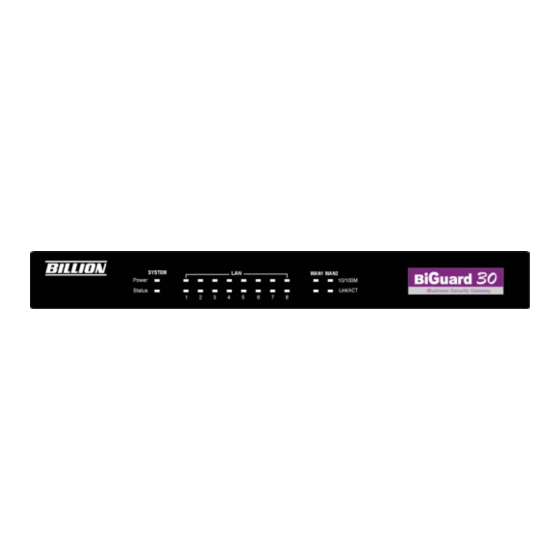
Function Power A solid light indicates a steady connection to a power source. Status A blinking light indicates the device is writing to flash memory. Lit when connected to an Ethernet device. 1 – 8 10/100M : Lit green when connected at 100Mbps. Not lit when connected at 10Mbps. -
Page 13: Rack Mounting
DC12V Connect DC Power Adapter here. (12VDC) 1.3.3 Rack Mounting To rack mount BiGuard 30, carefully secure the device to your rack on both sides using the included brackets and screws. See the diagram below for a more detailed explanation. -
Page 14: Cabling
One of the most common causes of networking problems is bad cabling. Make sure that all connected devices are turned on. On the front panel of BiGuard 30, verify that the LAN link and WAN line LEDs are lit. If they are not, check to see that you are... -
Page 15: Chapter 2: Router Applications
Chapter 2: Router Applications 2.1 Overview Your BiGuard 30 router is a versatile device that can be configured to not only protect your network from malicious attackers, but also ensure optimal usage of available bandwidth with Quality of Service (QoS) and both Inbound and Outbound Load Balancing. -
Page 16: Qos Policies For Different Applications
2.2.2 QoS Policies for Different Applications By setting different QoS policies according to the applications you are running, you can use BiGuard 30 to optimize the bandwidth that is being used on your network. VoIP Normal PCs Restricted PC As illustrated in the diagram above, applications such as Voiceover IP (VoIP) require... -
Page 17: Guaranteed / Maximum Bandwidth
2.2.3 Guaranteed / Maximum Bandwidth Setting a Guaranteed Bandwidth ensures that a particular service receives a minimum percentage of bandwidth. For example, you can configure BiGuard 30 to reserve 10% of the available bandwidth for a particular computer on the network to transfer files. -
Page 18: Priority Bandwidth Utilization
2.2.5 Priority Bandwidth Utilization Assigning priority to a certain service allows BiGuard 30 to give either a higher or lower priority to traffic from this particular service. Assigning a higher priority to an application ensures that it is processed ahead of applications with a lower priority and vice versa. -
Page 19: Diffserv (Dscp Marking)
BiGuard 30 can also be configured to apply traffic policies based on a particular IP or MAC address. This allows you to quickly assign different traffic policies to a specific computer on the network. 2.2.7 DiffServ (DSCP Marking) DiffServ (a.k.a. DSCP Marking) allows you to classify traffic based on IP DSCP values. -
Page 20: Outbound Traffic
2.3 Outbound Traffic This section outlines some of the ways you can use BiGuard 30 to manage outbound traffic. 2.3.1 Outbound Fail Over Configuring BiGuard 30 for Outbound Fail Over allows you to ensure that outgoing traffic is uninterrupted by having BiGuard 30 default to WAN2 should WAN1 fail. -
Page 21: Inbound Traffic
IP address of the client. By balancing the load between WAN1 and WAN2, your BiGuard 30 can ensure that outbound traffic is efficiently handled by making sure that both ports are equally sharing the load, preventing situations where one port is completely saturated by outbound traffic. -
Page 22: Inbound Load Balancing
In the above example, an FTP Server (IP_192.168.2.2) and an HTTP Server (IP_192.168.2.3) are connected to the Internet via WAN1 (ftp.billion.dyndns.org) on BiGuard 30. A remote computer is trying to access these servers via the Internet. Under normal circumstances, the remote computer will gain access to the network via WAN1. -
Page 23: Dns Inbound
For example, a sales force can be directed to www.billion2.dyndns.org, while the R&D group can access www.billion3.dyndns.org. By balancing the load between WAN1 and WAN2, your BiGuard 30 can ensure that inbound traffic is efficiently handled with both ports equally sharing the load, preventing situations where service is slow because one port is completely saturated by inbound traffic. -
Page 24: Dns Inbound Fail Over
DNS Inbound is a three step process. First, a DNS request is made to the router via a remote PC. BiGuard 30, based on settings specified by the user, will direct the requesting PC to the correct WAN port by replying the selected WAN IP address through the built-in DNS server. -
Page 25: Dns Inbound Load Balancing
In the above example, an FTP Server (IP_192.168.2.2) and an HTTP Server (IP_192.168.2.3) are connected to the Internet via WAN1 (IP_200.200.200.1) on BiGuard 30. A remote computer is trying to access these servers via the Internet, and makes a DNS request. The DNS request (www.mydomain.com) will be sent through WAN1 (200.200.200.1) to the built-in DNS server. - Page 26 If WAN2 is experiencing a heavy load, BiGuard 30 responds to incoming DNS requests with WAN1. By balancing the load between WAN1 and WAN2, your BiGuard 30 can ensure that inbound traffic is efficiently handled, making sure that both ports are equally sharing the load and preventing situations where service is slow because one port is completely saturated by inbound traffic.
-
Page 27: Virtual Private Networking
WAN1 and WAN2 and decide which WAN IP to reply to the request (3). After the decision is made, BiGuard 30 will route the DNS reply to the user through WAN2 (4). The user will receive the DNS reply with the IP address of WAN1 (5). The browser will initiate an HTTP request to the WAN1 IP address (6). -
Page 28: General Vpn Setup
The following section discusses Virtual Private Networking with BiGuard 30. 2.6.1 General VPN Setup There are typically three different VPN scenarios. The first is a Gateway to Gateway setup, where two remote gateways communicate over the Internet via a secure tunnel. -
Page 29: Vpn Planning - Fail Over
The following sections demonstrate the various ways of using BiGuard 30 to setup your VPN. 2.6.2 VPN Planning - Fail Over Configuring your VPN with Fail Over allows BiGuard 30 to automatically default to WAN2 should WAN1 fail. biguard.billion.com 192.168.3.x... -
Page 30: Concentrator
VPN tunnel to headquarter with the exception of LAN-side traffic. This way, all branch offices can connect to each other through headquarter via the headquarter’s firewall management. You can also configure BiGuard 30 to function as a VPN Concentrator: Please refer to appendix H for example settings. -
Page 31: Chapter 3: Getting Started
Linux, Mac OS, and Windows 98/Me/NT/2000/XP operating systems. The following chapter takes you through the very first steps to configuring your network for BiGuard 30. Take a look and see how easy it is to get your network up and running. 3.2 Before You Begin BiGuard 30 is a flexible and powerful networking device. -
Page 32: Connecting Your Router
4. Prepare to physically connect BiGuard 30 to Cable or DSL modems and a computer. Be sure to also review the Safety Warnings located in the preface of this manual before working with your BiGuard 30. -
Page 33: Configuring Pcs For Tcp/Ip Networking
DHCP server. If using a fixed IP address, it is important to remember that it must be in the same subnet as the router. The default IP address of BiGuard 30 is 192.168.1.254 with a subnet mask of 255.255.255.0. Using the default configuration, networked PCs must reside in the same subnet, and have an IP address in the range of 192.168.1.1 to 192.168.1.253. -
Page 34: Windows Xp
If you are using Windows 3.1, you must purchase a third-party TCP/IP application package. Any TCP/IP capable workstation can be used to communicate with or through BiGuard 30. To configure other types of workstations, please consult the manufacturer’s documentation. 3.4.2 Windows XP 3.4.2.1... - Page 35 2. In the Network Connections window, right-click Local Area Connection and select Properties. 3. Select Internet Protocol (TCP/IP) and click Properties.
- Page 36 4a. To have your PC obtain an IP address automatically, select the Obtain an IP address automatically and Obtain DNS server address automatically radio buttons. 4b. To manually assign your PC a fixed IP address, select the Use the following IP address radio button and enter your desired IP address, subnet mask, and default gateway in the blanks provided.
-
Page 37: Verifying Settings
5. Click OK to finish the configuration. 3.4.2.2 Verifying Settings To verify your settings using a command prompt: 1. Click Start > Programs > Accessories > Command Prompt. 2. In the Command Prompt window, type ipconfig and then press ENTER. - Page 38 If you are using BiGuard 30’s default settings, your PC should have: - An IP address between 192.168.1.1 and 192.168.1.253 - A subnet mask of 255.255.255.0 To verify your settings using the Windows XP GUI: 1. Click Start > Settings > Network Connections.
- Page 39 2. Right click one of the network connections listed and select Status from the pop-up menu. 3. Click the Support tab.
-
Page 40: Windows 2000
If you are using BiGuard 30’s default settings, your PC should: - Have an IP address between 192.168.1.1 and 192.168.1.253 - Have a subnet mask of 255.255.255.0 3.4.3 Windows 2000 3.4.3.1 Configuring 1. Select Start > Settings > Control Panel. - Page 41 2. In the Control Panel window, double-click Network and Dial-up Connections. 3. In Network and Dial-up Connections, double-click Local Area Connection.
- Page 42 4. In the Local Area Connection window, click Properties. 5. Select Internet Protocol (TCP/IP) and click Properties.
- Page 43 6a. To have your PC obtain an IP address automatically, select the Obtain an IP address automatically and Obtain DNS server address automatically radio buttons. 6b. To manually assign your PC a fixed IP address, select the Use the following IP address radio button and enter your desired IP address, subnet mask, and default gateway in the blanks provided.
-
Page 44: Verifying Settings
7. Click OK to finish the configuration. 3.4.3.2 Verifying Settings 1. Click Start > Programs > Accessories > Command Prompt. 2. In the Command Prompt window, type ipconfig and then press ENTER. -
Page 45: Windows 98 / Me
If you are using BiGuard 30’s default settings, your PC should have: - An IP address between 192.168.1.1 and 192.168.1.253 - A subnet mask of 255.255.255.0 3.4.4 Windows 98 / Me 3.4.4.1 Installing Components To prepare Windows 98/Me PCs for TCP/IP networking, you may need to manually install TCP/IP on each PC. - Page 46 2. Double-click the Network icon. The Network window displays a list of installed components.
- Page 47 You must have the following installed: - An Ethernet adapter - TCP/IP protocol - Client for Microsoft Networks If you need to install a new Ethernet adapter, follow these steps: a. Click Add. b. Select Adapter, then Add.
- Page 48 c. Select the manufacturer and model of your Ethernet adapter, then click OK. If you need TCP/IP: a. Click Add.
- Page 49 b. Select Protocol, then click Add. c. Select Microsoft. TCP/IP, then OK. If you need Client for Microsoft Networks: a. Click Add.
-
Page 50: Configuring
b. Select Client, then click Add. c. Select Microsoft. Client for Microsoft Networks, and then click OK. 3. Restart your PC to apply your changes. 3.4.4.2 Configuring 1. Select Start > Settings > Control Panel. - Page 51 2. In the Control Panel, double-click Network and choose the Configuration tab.
- Page 52 3. Select TCP / IP > ASUSTek or the name of any Network Interface Card (NIC) in your PC and click Properties. 4. Select the IP Address tab and click the Obtain an IP address automatically radio button.
- Page 53 5. Select the DNS Configuration tab and select the Disable DNS radio button. 6. Click OK to apply the configuration.
-
Page 54: Verifying Settings
3.4.4.3 Verifying Settings To check the TCP/IP configuration, use the winipcfg.exe utility: 1. Select Start > Run. 2. Type winipcfg, and then click OK. 3. From the drop-down box, select your Ethernet adapter. -
Page 55: Factory Default Settings
The window is updated to show your settings. Using the default BiGuard 30 settings, your PC should have: - An IP address between 192.168.1.1 and 192.168.1.253 - A subnet mask of 255.255.255.0 - A default gateway of 192.168.1.254 3.5 Factory Default Settings... -
Page 56: Username And Password
The Status LED will remain solid as the device boots. Once the boot sequence is complete, the LED will shut off, indicating that BiGuard 30 is ready. 3.5.2 LAN and WAN Port Addresses... -
Page 57: Configuration Information
If your account uses PPP over Ethernet (PPPoE), you will need to enter your login name and password when configuring your BiGuard 30. After the network and firewall are configured, BiGuard 30 will login automatically, and you will no longer need to run the login program from your PC. -
Page 58: Windows
3.6.2.1 Windows This section uses illustrations from Windows XP. However, other versions of Windows will follow a similar procedure. Have your Windows CD handy, as it may be required during the configuration process. 1. Select Start > Settings > Control Panel. 2. - Page 59 3. In the Network Connections window, right-click Local Area Connection and select Properties. 4. Select Internet Protocol (TCP/IP) and click Properties.
- Page 60 5. If an IP address, subnet mask and a Default gateway are shown, write down the information. If no address is present, your account’s IP address is dynamically assigned. Click the Obtain an IP address automatically radio button. 6. If any DNS server addresses are shown, write them down. Click the Obtain DNS server address automatically radio button.
-
Page 61: Web Configuration Interface
7. Click OK to save your changes. 3.7 Web Configuration Interface BiGuard 30 includes a Web Configuration Interface for easy administration via virtually any browser on your network. To access this interface, open your web browser, enter the IP address of your router, which by default is 192.168.1.254, and click Go. - Page 62 If the Web Configuration Interface appears, congratulations! You are now ready to configure your BiGuard 30. If you are having trouble accessing the interface, please refer to Chapter 5: Troubleshooting for possible resolutions.
-
Page 63: Chapter 4: Router Configuration
Chapter 4: Router Configuration 4.1 Overview The Web Configuration Interface makes it easy for you to manage your network via any PC connected to it. On the Web Configuration homepage, you will see the navigation pane located on the left hand side. From it, you will be able to select various options used to configure your router. -
Page 64: Status
4.2 Status The Status menu displays the various options that have been selected and a number of statistics about your BiGuard 30. In this menu, you will find the following sections: - ARP Table - Routing Table - Session Table... -
Page 65: Arp Table
4.2.1 ARP Table The Address Resolution Protocol (ARP) Table shows the mapping of Internet (IP) addresses to Ethernet (MAC) addresses. This is a quick way to determine the MAC address of your PC’s network interface to use with the router’s Firewall – MAC Address Filter function. -
Page 66: Routing Table
4.2.2 Routing Table The Routing Table displays the current path for transmitted packets. Both static and dynamic routes are displayed. No.: Number of the list. Destination: The IP address of the destination network. Netmask: The destination netmask address. Gateway/Interface: The IP address of the gateway or existing interface that this route will use. -
Page 67: Session Table
4.2.3 Session Table The NAT Session Table displays a list of current sessions for both incoming and outgoing traffic with protocol type, source IP, source port, destination IP and destination port, each page shows 10 sessions. No.: Number of the list. Protocol: Protocol type of the Session. -
Page 68: Dhcp Table
4.2.4 DHCP Table The DHCP Table displays a list of IP addresses that have been assigned to PCs on your network via Dynamic Host Configuration Protocol (DHCP). No.: Number of the list. IP Address: A list of IP addresses of devices on your LAN. Device Name: The host name (computer name) of the client. -
Page 69: Ipsec Status
4.2.5 IPSec Status The IPSec Status window displays the status of the IPSec Tunnels that are currently configured on your BiGuard 30. Name: The name you assigned to the particular IPSec entry. Enable: Whether the IPSec connection is currently Enable or Disable. -
Page 70: Pptp Status
4.2.6 PPTP Status The PPTP Status window displays the status of the PPTP Tunnels that are currently configured on your BiGuard 30. Name: The name you assigned to the particular PPTP entry. Enable: Whether the PPTP connection is currently Enable or Disable. -
Page 71: Traffic Statistics
4.2.7 Traffic Statistics The Traffic Statistics window displays both sent and received sent data (in Bytes/sec) over a one hour duration. The line in red represents WAN1, while the line in blue represents WAN2. WAN1: Transmitted (Tx) and Received (Rx) bytes and packets for WAN1. WAN2: Transmitted (Tx) and Received (Rx) bytes and packets for WAN2. -
Page 72: System Log
4.2.8 System Log This window displays BiGuard 30’s System Log entries. Major events are logged on this window. Refresh: Refresh the System Log. Clear Log: Clear the System Log. Send Log: Send the System Log to your email account. You can set the email address in Configuration >... -
Page 73: Ipsec Log
4.2.9 IPSec Log This page displays the router’s IPSec Log entries. Major events are logged to this window. Refresh: Refresh the IPSec Log. Clear Log: Clear the IPSec Log. Send Log: Send IPSec Log to your email account. You can set the email address in Configuration >... -
Page 74: Dhcp
4.3.1 DHCP The following is information regarding your ISP that you will need to enter in order to properly configure your Internet connection. If you select to Obtain an IP Address Automatically, these will be automatically set for you, provided that your ISP dynamically assigns an IP address. -
Page 75: Pppoe
IP assigned by your ISP: Enter the assigned IP address from your IP. IP Subnet Mask: Enter your IP subnet mask. ISP Gateway Address: Enter your ISP gateway address. Primary DNS: Enter your primary DNS. Secondary DNS: Enter your secondary DNS. Click Apply to save your changes. -
Page 76: Pptp
4.3.4 PPTP Username: Enter your user name. Password: Enter your password. Retype Password: Retype your password. PPTP Client IP: Enter the PPTP Client IP provided by your ISP. PPTP Client IP Netmask: Enter the PPTP Client IP Netmask provided by your ISP. PPTP Client IP Gateway: Enter the PPTP Client IP Gateway provided by your ISP. -
Page 77: Big Pond
For detailed instructions on configuring WAN settings, please refer to the WAN section of this chapter. 4.4 Configuration The Configuration menu allows you to set many of the operating parameters of BiGuard 30. In this menu, you will find the following sections: - LAN - WAN - Dual WAN... -
Page 78: Lan
- Virtual Server - Advanced These items are described below in the following sections. 4.4.1 LAN There are two items within this section: Ethernet and DHCP Server. -
Page 79: Ethernet
4.4.1.1 Ethernet IP Address: Enter the internal LAN IP address for BiGuard 30 (192.168.1.254 by default). Subnet Mask: Enter the subnet mask (255.255.255.0 by default). RIP: RIP v2 Broadcast and RIP v2 Multicast. Check to enable RIP. 4.4.1.2 DHCP Server In this menu, you can disable or enable the Dynamic Host Configuration Protocol (DHCP) server. - Page 80 To disable the router’s DHCP Server, select the Disable radio button, and then click Apply. When the DHCP Server is disabled, you will need to manually assign a fixed IP address to each PC on your network, and set the default gateway for each PC to the IP address of the router (192.168.1.254 by default).
- Page 81 IP Address: Enter the IP address that you want to reserve for the above MAC address. MAC Address: Enter the MAC address of the PC or server you wish to be assigned a reserved IP.
-
Page 82: Wan
Candidates: You can also select the Candidates which are referred from the ARP table for automatic input. Click the Apply button to add the configuration into the Host Table. Press the Delete button to delete a configuration from the Host Table. 4.4.2 WAN WAN refers to your Wide Area Network connection. - Page 83 This WAN Service Table displays the different WAN connections that are configured on BiGuard 30. To edit any of these connections, click Edit. You will be taken to the following menu. Connection Method: Select how your router will connect to the Internet. Selections...
-
Page 84: Dhcp
Settings, PPTP Settings, and Big Pond Settings. For each WAN port, the factory default is DHCP. If your ISP does not use DHCP, select the correct connection method and configure the connection accordingly. Configurable items will vary depending on the connection method selected. 4.4.2.1.1 DHCP Host Name: Some ISPs authenticate logins using this field. -
Page 85: Pppoe
IP assigned by your ISP: Enter the static IP assigned by your ISP. IP Subnet Mask: Enter the IP subnet mask provided by your ISP. ISP Gateway Address: Enter the ISP gateway address provided by your ISP. MAC Address: If your ISP requires you to input a WAN Ethernet MAC, check the checkbox and enter your MAC address in the blanks below. - Page 86 Username: Enter your user name. Password: Enter your password. Retype Password: Retype your password. Connection: Select whether the connection should Always Connect or Trigger on Demand. If you want the router to establish a PPPoE session when starting up and to automatically re-establish the PPPoE session when disconnected by the ISP, select Always Connect.
- Page 87 Click Apply to save your changes. To reset to defaults, click Reset. 4.4.2.1.4 PPTP Settings Username: Enter your user name. Password: Enter your password. Retype Password: Retype your password. PPTP Client IP: Enter the PPTP Client IP provided by your ISP. PPTP Client IP Netmask: Enter the PPTP Client IP Netmask provided by your ISP.
-
Page 88: Big Pond
Dynamic radio button. If your IP assigns a static IP address, select the Static radio button. This will take you to another page for inputting the IP address information. MAC Address: If your ISP requires you to input a WAN Ethernet MAC, check the checkbox and enter your MAC address in the blanks below. -
Page 89: Bandwidth Settings
RIP: To activate RIP, select Send, Receive, or Both from the drop down menu. To disable RIP, select Disable from the drop down menu. MTU: Enter the Maximum Transmission Unit (MTU) for your network. Click Apply to save your changes. To reset to defaults, click Reset. A simpler alternative is to select Quick Start from the main menu. -
Page 90: Dual Wan
4.4.3 Dual WAN In this section, you can setup the fail over or load balance function, outbound load balance or inbound load balance function, or setup specific protocol to bind with specific WAN port. In this menu are the following sections: General Settings, Outbound Load Balance, Inbound Load Balance, and Protocol Binding. -
Page 91: Outbound Load Balance
Click Apply to save your changes. 4.4.3.2 Outbound Load Balance Outbound Load Balancing on BiGuard 30 can be based on one of two methods: 1. By session mechanism 2. By IP address hash mechanism Choose one by clicking the corresponding radio button. -
Page 92: Inbound Load Balance
on weight of length capacity. Balance by Session weight: Balances session traffic based on a weight ratio. Enter the desired ratio in the blanks provided. Balance by Traffic (weight of length capacity): Balances traffic based on weight of link capacity. Balance by Traffic weight: Balances traffic based on a traffic weight ratio. - Page 93 Function: Used to enable or disable inbound load balancing. DNS Server 1: DNS Server 1 settings including Host URL mappings. DNS Server 2: DNS Server 2 settings including Host URL mappings. To edit server settings, click Edit. The following example illustrates DNS Server 1 settings.
- Page 94 Minimum TTL: The minimum time to live. Denoted in seconds. NS Record Name Server: The name of the Primary Name Server. MX Record Mail Exchanger: The name of the mail server. IP Address: The mail server IP address. Click Apply to save your changes. To edit the Host Mapping URL list, click Edit.
-
Page 95: Protocol Binding
Domain Name: The domain name of the local host. Host URL: The URL to be mapped. Private IP Address: The IP address of the local host. Helper: You could also select the application type you would like to apply for automatic input. - Page 96 (NOTE: If any policies are added in the Protocol Binding section, please note that it would take precedence over the settings that are already configured in the Load Balance Setting section.) The Protocol Binding Table lists any protocol binding that has been configured. To Create.
- Page 97 Interface: Choose which WAN port to use: WAN1, WAN2 Packet Type: The particular protocol of Internet traffic for the specified policy. Choose from TCP, UDP, or Any. Source IP Range: All Source IP: Click it to specify all source IPs. Specified Source IP: Click to specify a specific source IP address and source IP netmask.
-
Page 98: System
4.4.4 System The System menu allows you to adjust a variety of basic router settings, upgrade firmware, set up remote access, and more. In this menu are the following sections: Time Zone, Remote Access, Firmware Upgrade, Backup/Restore, Restart, Password, System Log and Email Alert. 4.4.4.1 Time Zone... -
Page 99: Remote Access
Simply choose your local time zone, enter NTP Server IP Address, and click Apply. After connecting to the Internet, BiGuard 30 will retrieve the correct local time from the NTP server you have specified. Your ISP may provide an NTP server for you to use. -
Page 100: Firmware Upgrade
4.4.4.3 Firmware Upgrade Upgrading your BiGuard 30’s firmware is a quick and easy way to enjoy increased functionality, better reliability, and ensure trouble-free operation. To upgrade your firmware, simply visit Billion’s website (http://www.billion.com) and download the latest firmware image file for BiGuard 30. Next, click Browse and select the newly downloaded firmware file. -
Page 101: Backup / Restore
4.4.4.4 Backup / Restore This feature allows you to save and backup your router’s current settings, or restore a previously saved backup. This is useful if you wish to experiment with different settings, knowing that you have a backup handy. It is advisable to backup your router’s settings before making any significant changes to your router’s configuration. -
Page 102: Restart
4.4.4.5 Restart The Restart feature allows you to easily restart BiGuard 30. To restart with your last saved configuration, select the Current Settings radio button and click Restart. If you wish to restart the router using the factory default settings, select Factory Default Settings and click Restart to reboot BiGuard 30 with factory default settings. -
Page 103: Password
4.4.4.6 Password In order to prevent unauthorized access to your router’s configuration interface, it requires the administrator to login with a password. You can change your password by entering your new password in both fields. Click Apply to save your changes. Click Reset to reset to the default administration password (admin). -
Page 104: System Log Server
4.4.4.7 System Log Server This function allows BiGuard 30 to send system logs to an external Syslog Server. Syslog is an industry-standard protocol used to capture information about network activity. To enable this function, select the Enable radio button and enter your Syslog server IP address in the Log Server IP Address field. -
Page 105: Email Alert
4.4.4.8 E-mail Alert The Email Alert function allows a log of security-related events (such as System Log and IPSec Log) to be sent to a specified email address. Email Alert: You may enable or disable this function by selecting the appropriate radio button. -
Page 106: Firewall
When log is full: The router will send an alert only when the log is full. 4.4.5 Firewall BiGuard 30 includes a full Stateful Packet Inspection (SPI) firewall for controlling Internet access from your LAN, and preventing attacks from hackers. Your router also acts as a "natural"... -
Page 107: Packet Filter
4.4.5.1 Packet Filter The Packet Filter function is used to limit user access to certain sites on the Internet or LAN. The Filter Table displays all current filter rules. If there is an entry in the Filter Table, you can click Edit to modify the setting of this entry, click Delete to remove this entry, or click Move to change this entry’s priority. -
Page 108: End Ip Address
ID: This is an identify that allows you to move the rule by before or after an ID. Rule: Enable or Disable this entry. Action When Matched: Select to Drop or Forward the packet specified in this filter entry. Direction: Incoming Packet Filter rules prevent unauthorized computers or applications accessing your local network from the Internet. -
Page 109: Url Filter
Source Port Range: Enter the source port number range. If you only want to specify one service port, then enter the same port number in both boxes. Destination Port Range: Enter the destination port number range. If you only want to specify one service port, then enter the same port number in both boxes. - Page 110 components. Click "Block ActiveX" to filter web access with ActiveX components. Click "Block Web proxy" to filter web proxy access. Click "Block Cookie" to filter web access with Cookie components. Click "Block Surfing by IP Address" to filter web access with an IP address as the domain name. Exception List: You can input a list of IP addresses as the exception list for URL filtering.
- Page 111 Enter a domain and select whether this domain is trusted or forbidden with the pull-down menu. Next, click Apply. Your new domain will be added to either the Trusted Domain or Forbidden Domain listing, depending on which you selected previously. Restrict URL Features: Use this to disable certain web features.
-
Page 112: Lan Mac Filter
Enter a name for the IP Address and then enter the IP address itself. Click Apply to save your changes. The IP address will be entered into the Exception List, and excluded from the URL filtering rules in effect. 4.4.5.3 LAN MAC Filter LAN Mac Filter can decide that BiGuard will serve those devices at LAN side or not by MAC Address. -
Page 113: Block Wan Request
Rule: Enable or disable this entry. Action When Matched: Select to Drop or Forward the packet specified in this filter entry. MAC Address: The MAC Address you would like to apply. Candidates: You can also select the Candidates which are referred from the ARP table for automatic input. -
Page 114: Intrusion Detection
Blocking WAN requests is one way to prevent DDOS attacks by preventing ping requests from the Internet. Use this menu to enable or disable function. 4.4.5.5 Intrusion Detection Intrusion Detection can prevent most common DoS attacks from the Internet or from LAN users. -
Page 115: Ipsec Wizard
4.4.6.1.1 IPSec Wizard Connection Name: A user-defined name for the connection. Interface: Select the interface the IPSec tunnel will apply to. WAN1: Select interface WAN1 WAN2: Select interface WAN2 Auto: The device will automatically apply the tunnel to WAN1 or WAN2 depending on which WAN interface is active when the IPSec tunnel is being established. - Page 116 Connection Type: There are 5 connection types: (1)LAN to LAN: BiGuard would like to establish an IPSec VPN tunnel with remote router using Fixed Internet IP or domain name by using main mode. Secure Gateway Address (or Domain Name): The IP address or hostname of the remote VPN gateway.
- Page 117 (2)LAN to Mobile LAN: BiGuard would like to establish an IPSec VPN tunnel with remote router using Dynamic Internet IP by using aggressive mode. Remote Identifier: The Identifier of the remote gateway. According to the input value, the ID type will be auto-defined as IP Address, FQDN(DNS) or FQUN(E-mail). Remote Network: The subnet of the remote network.
- Page 118 (3)LAN to Host: BiGuard would like to establish an IPSec VPN tunnel with remote client software using Fixed Internet IP or domain name by using main mode. Secure Gateway Address (or Domain Name): The IP address or hostname of the remote VPN device that is connected and establishes a VPN tunnel.
- Page 119 (4)LAN to Mobile Host: BiGuard would like to establish an IPSec VPN tunnel with remote client software using Dynamic Internet IP by using aggressive mode. Remote Identifier: The Identifier of the remote gateway. According to the input value, the ID type will be auto-defined as IP Address, FQDN(DNS) or FQUN(E-mail). Back: Back to the Previous page.
- Page 120 (5)LAN to Host (for BiGuard VPN Client only): BiGuard would like to establish an IPSec VPN tunnel with BiGuard VPN Client software C01 by using aggressive mode. VPN Client IP Address: The VPN Client Address for BiGuard VPN Client, this value will be applied on both remote ID and Remote Network as single address.
-
Page 121: Ipsec Policy
After your configuration is done, you will see a Configuration Summary. Back: Back to the Previous page. Done: Click Done to apply the rule. 4.4.6.1.2 IPSec Policy Click Create to create a new IPSec VPN connection account. - Page 122 Configuring a New VPN Connection Connection Name: A user-defined name for the connection. Tunnel: Select Enable to activate this tunnel. Select Disable to deactivate this tunnel. Interface: Select the interface the IPSec tunnel will apply to. WAN1: Select interface WAN1 WAN2: Select interface WAN2 Auto: The device will automatically apply the tunnel to WAN1 or WAN2 depending on which WAN interface is active when the IPSec tunnel is being...
- Page 123 router will automatically seek the IP address of the FQDN. FQUN E-Mail(Fully Qualified User Name): Consists of a username and its domain name. For example, user@vpn.com is a FQUN. "user" is the username and "vpn.com" is the domain name. Data: Enter the ID data using the specific ID type. Network: Set the IP address, IP range, subnet, or address range of the local network.
- Page 124 degrees of security and speed of negotiation: Main Mode: Uses the automated Internet Key Exchange (IKE) setup; most secure method with the highest level of security. Aggressive Mode: Uses the automated Internet Key Exchange (IKE) setup; mid-level security. Speed is faster than Main mode. Manual Key: Standard level of security.
-
Page 125: Pptp
Key Life Time: Allows you to specify the timer interval for renegotiation of another key. The value is in seconds eg. 3600 seconds = 1 hour. Netbios Broadcast: Allows BiGuard to send local Netbios Broadcast packet through the IPSec Tunnel, please select Enable or Disable. Click the Apply button to save your changes. - Page 126 IP Addresses Assigned to Peer Start from: 192.168.1.x: please input the IP assigned range from 1 ~ 254 (except BiGuard 30’s LAN IP address with 192.168.1.254 as BiGuard 30’s default LAN IP address and IP pool range of DHCP server settings with 100~199 as BiGuard 30’s default DHCP IP pool range.) Idle Timeout “...
-
Page 127: Qos
PPTP Tunnel, please select Enable or Disable. 4.4.7 QoS BiGuard 30 can optimize your bandwidth by assigning priority to both inbound and outbound data with QoS. This menu allows you to configure QoS for both inbound and outbound traffic. - Page 128 The first menu screen gives you an overview of which WAN ports currently have QoS active, and the bandwidth settings for each. WAN1 Outbound: QoS Function: QoS status for WAN1 outbound. Select Enable to activate QoS for WAN1’s outgoing traffic. Select Disable to deactivate. Max ISP Bandwidth: The maximum bandwidth afforded by the ISP for WAN1’s outbound traffic.
- Page 129 Creating a New QoS Rule To get started using QoS, you will need to establish QoS rules. These rules tell BiGuard 30 how to handle both incoming and outgoing traffic. The following example shows you how to configure WAN1 Outbound QoS. Configuring the other traffic types follows the same process.
- Page 130 Interface: The current traffic type. This can be WAN1 (outbound, inbound) and WAN2 (outbound, inbound). Application: User defined application name for the current rule. Packet Type: The type of packet this rule applies to. Choose from Any, TCP, UDP, or ICMP. Guaranteed: The guaranteed amount of bandwidth for this rule as a percentage.
-
Page 131: Virtual Server
For MAC Address: Source MAC Address: The source MAC Address of the device this rule applies to. Candidates: You can also select the Candidates which are referred from the ARP table for automatic input. Source Port Range: The range of source ports this rule applies to. Destination Port Range: The range of destination ports this rule applies to. -
Page 132: Dmz
PCs. Please see the WAN Configuration section of this manual for more information on NAT. BiGuard 30 can also be configured as a virtual server so that remote users accessing services such as Web or FTP services via the public (WAN) IP address can be automatically redirected to local servers in the LAN network. -
Page 133: Port Forwarding Table
Enable DMZ function: Enable: Activates your router’s DMZ function. Disable: Default setting. Disables the DMZ function. DMZ IP Address: Give a static IP address to the DMZ Host when the Enable radio button is selected. Be aware this IP will be exposed to the WAN/Internet. Candidates: You can also select the Candidates which are referred from the ARP table for automatic input. - Page 134 POP3 (port 110). When an incoming access request is received, it will be forwarded to the corresponding internal server. Click Create to add a new port forwarding rule. This function allows any incoming data addressed to a range of service port numbers (from the Internet/WAN Port) to be re-directed to a particular LAN private/internal IP address.
- Page 135 Application: User defined application name for the current rule. Helper: You could also select the application type you would like to apply for automatic input. Protocol type: please select protocol type External Port: Enter the port number of the service that will be sent to the Internal IP address.
-
Page 136: Advanced
4.4.9 Advanced Configuration options within the Advanced section are for users who wish to take advantage of the more advanced features of BiGuard 30. Users who do not understand the features should not attempt to reconfigure their router, unless advised to do so by support staff. -
Page 137: Dynamic Dns
Rule: Select Enable to activate this rule, Disable to deactivate this rule. Destination: This is the destination subnet IP address. Netmask: This is the subnet mask of the destination IP addresses based on above destination subnet IP. Gateway: This is the gateway IP address to which packets are to be forwarded. Interface: Select the interface through which packets are to be forwarded. - Page 138 You will first need to register and establish an account with the Dynamic DNS provider using their website, Example: DYNDNS http://www.dyndns.org/ (BiGuard 30 supports several Dynamic DNS providers , such as www.dyndns.org www.orgdns.org , www.dhs.org, www.dyns.cx, www.3domain.hk, www.dyndns.org , www.3322.org ) Dynamic DNS: Disable: Check to disable the Dynamic DNS function.
-
Page 139: Device Management
4.4.9.3 Device Management The Device Management Advanced Configuration settings allow you to control your router’s security options and device monitoring features. Device Name Name: Enter a name for this device. Web Server Settings HTTP Port: This is the port number the router’s embedded web server (for web-based configuration) will use. -
Page 140: Save Configuration To Flash
the device will automatically logout User A. SNMP Access Control Select to activate this function, to deactivate this SNMP Function: Enable Disable function. SNMP V1 and V2 Input the string for Read community to match your SNMP Read Community: software. Input the string for Write community to match your SNMP Write Community: software. -
Page 141: Logout
4.6 Logout To exit the router’s web interface, click Logout. Please ensure that you have saved your configuration settings before you logout. Be aware that the router is restricted to only one PC accessing the web configuration interface at a time. Once a PC has logged into the web interface, other PCs cannot gain access until the current PC has logged out. -
Page 142: Chapter 5: Troubleshooting
5.1.2 LEDs Never Turn Off When your BiGuard 30 is turned on, the LEDs turn on for about 10 seconds and then turn off. If all the LEDs stay on, there may be a hardware problem. If all LEDs are still on one minute after powering up: - Cycle the power to see if the router recovers. -
Page 143: Forgot My Password
Please note that both the User Name and Password are case-sensitive. If this fails, you can restore your BiGuard 30 to its factory default settings by holding the Reset button on the back of your router until the Status LED begins to blink. -
Page 144: Can't Access Web Configuration Interface
- Check the 10/100 LAN LEDs on BiGuard 30’s front panel. One of these LEDs should be on. If they are both off, check the cables between BiGuard 30 and the hub or PC. - Check the corresponding LAN LEDs on your PC’s Ethernet device are on. - Page 145 3. Make sure that the Delete All Offline Content checkbox is checked, and click 4. Click OK under Internet Options to close the dialogue. - In Windows, type arp –d at the command prompt to clear you computer’s ARP table.
-
Page 146: Pop-Up Windows
To use the Web Configuration Interface, you need to disable pop-up blocking. You can either disable pop-up blocking, which is enabled by default in Windows XP Service Pack 2, or create an exception for your BiGuard 30’s IP address. Disabling All Pop-ups In Internet Explorer, select Tools >... -
Page 147: Java Permissions
3. Under Scripting, check to see if Active scripting is set to Enable. 4. Ensure that Scripting of Java applets is set to Enabled. 5. Click OK to close the dialogue. 5.2.3.3 Java Permissions The following Java Permissions should also be given for the Web Configuration Interface to display properly: 1. -
Page 148: Wan Interface
BiGuard 30’s system name. 5.4 ISP Connection Unless you have been assigned a static IP address by your ISP, your BiGuard 30 will need to request an IP address from the ISP in order to access the Internet. If your BiGuard 30 is unable to access the Internet, first determine if your router is able to obtain a WAN IP address from the ISP. - Page 149 If an IP address cannot be obtained: 1. Turn off the power to your cable or DSL modem. 2. Turn off the power to your BiGuard 30. 3. Wait five minutes and power on your cable or DSL modem. 4. When the modem has finished synchronizing with the ISP (generally shown by LEDs on the modem), turn on the power to your router.
-
Page 150: Problems With Date And Time
Configuration > System > Time Zone. 5.6 Restoring Factory Defaults You can restore your BiGuard 30 to its factory settings by holding the Reset button on the back of your router until the Status LED begins to blink. This will reset your... -
Page 151: Appendix A: Product Specifications
Appendix A: Product Specifications Availability and Resilience - Dual-WAN ports - Load balancing for increased bandwidth of inbound and outbound traffic - Automatic failover to redirect the packet when one broadband connection is broken. It will keep your Internet connection always online whenever one connection should fail. -
Page 152: Content Filtering
Content Filtering - URL Filter settings prevent user access to certain sites on the Internet - Java Applet/Active X/Cookie Blocking Quality of Service Control - Supports DiffServ approach - Traffic prioritization and bandwidth management based-on IP protocol, port number and IP or MAC address Web-Based Management - Easy-to-use WEB interface - Firmware upgradeable via WEB interface... -
Page 153: Appendix B: Customer Support
Appendix B: Customer Support Most problems can be solved by referring to the Troubleshooting section in the User’s Manual. If you cannot resolve the problem with the Troubleshooting chapter, please contact the dealer where you purchased this product. Contact Billion Worldwide http://www.billion.com/... -
Page 154: Appendix C: Fcc Interference Statement
Appendix C: FCC Interference Statement This device complies with Part 15 of FCC rules. Operation is subject to the following two conditions: - This device may not cause harmful interference. - This device must accept any interference received, including interference that may cause undesired operations. -
Page 155: Appendix D: Network, Routing, And Firewall Basics
Appendix D: Network, Routing, and Firewall Basics D.1 Network Basics D.1.1 IP Addresses With the number of TCP/IP networks interconnected across the globe, ensuring that transmitted data reaches the correct destination requires each computer on the Internet has a unique identifier. This identifier is known as the IP address. The Internet Protocol (IP) uses a 32-bit address structure, and the address is usually written in dot notation. -
Page 156: Subnet Addressing
back slash (/). For example, a typical Class C address could be written as 192.168.234.245/24, which means that the net mask is 24 ones followed by 8 zeros. (11111111 11111111 11111111 00000000). D.1.1.2 Subnet Addressing Subnet addressing enables the split of one IP network address into multiple physical networks. -
Page 157: Network Address Translation (Nat)
In addition, other information such as gateway and DNS address can also be assigned with a DHCP server. When connecting to the ISP, BiGuard 30 also functions as a DHCP client. BiGuard 30 can automatically obtain an IP address, subnet mask, gateway address, and DNS server addresses if the ISP assigns this information via DHCP. -
Page 158: Router Basics
Routers can vary in performance and scale, the types of physical WAN connection they support, and the number of routing protocols supported. BiGuard 30 offers a convenient and powerful way for small-to-medium businesses to connect their networks. -
Page 159: Firewall Basics
D.3.1.1 Stateful Packet Inspection BiGuard 30 uses Stateful Packet Inspection (SPI) to protect your network from intrusions and attacks. Unlike less sophisticated Internet sharing routers, SPI ensures secure firewall filtering by intercepting incoming packets at the network layer, and analyzing them for state-related information that is associated with all network connections. -
Page 160: Why Use A Firewall
Internet. Still, there are ways for more dedicated hackers to either obtain information about your network or disrupt your network’s Internet access. Your BiGuard 30 provides an extra level of protection from such attacks with its built-in firewall. -
Page 161: Appendix E: Virtual Private Networking
Appendix E: Virtual Private Networking E.1 What is a VPN? A Virtual Private Network (VPN) is a shared network where private data is segmented from other traffic so that only the intended recipient has access. It allows organizations to securely transmit data over a public medium like the Internet. -
Page 162: Ipsec Security Components
data authentication, integrity, and confidentiality as data is transferred across IP networks. IPSec provides data security at the IP packet level, and protects against possible security risks by protecting data. IPSec is widely used to establish VPNs. There are three major functions of IPSec: - Confidentiality: Conceals data through encryption. -
Page 163: Encapsulating Security Payload (Esp)
Next Payload Reserved Header Length Sequence Number Authentication Data E.2.1.2 Encapsulating Security Payload (ESP) Encapsulating Security Payload (ESP) provides privacy for data through encryption. An encryption algorithm combines the data with a key to encrypt it. It then repackages the data using a special format, and transmits it to the destination. The receiver then decrypts the data using the same algorithm. -
Page 164: Security Associations (Sa)
Sequence Number Data Next Authentication Data E.2.1.3 Security Associations (SA) Security Associations are a one-way relationships between sender and receiver that specify IPSec-related parameters. They provide data protection by using the defined IPSec protocols, and allow organizations to control according to the security policy in effect, which resources may communicate securely. -
Page 165: Tunnel Mode Ah
AH/E Transport Mode - This mode is used to provide data security between two networks. It provides protection for the entire IP packet and is sent by adding an outer IP header corresponding to the two tunnel end-points. Since tunnel mode hides the original IP header, it provides security of the networks with private IP address space. -
Page 166: Tunnel Mode Esp
E.2.4 Tunnel Mode ESP Here is an example of a packet with ESP applied: Original Packet Data IP Header Packet with IPSec Encapsulation Security Payload New IP Header ESP Header Data ESP Trailer Org IP Header Authentication encrypted Authenticated E.2.5 Internet Key Exchange (IKE) Before either AH or ESP can be used, it is necessary for the two communication devices to exchange a secret key that the security protocols themselves will use. - Page 167 encryption, and is more vulnerable to Denial of Service attacks. Phase II, known as Quick Mode, establishes symmetrical IPSec Security Associations for both AH and ESP. It does this by negotiating IPSec parameters, exchange nonces to derive session keys from the IKE shared secret, exchange DH values to generate a new key, and identify which traffic this SA bundle will protect using selectors (IDi and IDr payloads).
-
Page 168: Appendix F: Ipsec Logs And Events
Appendix F: IPSec Logs and Events F.1 IPSec Log Event Categories There are three major categories of IPSec Log Events for your BiGuard 30. These include: 1. IKE Negotiate Packet Messages 2. Rejected IKE Messages 3. IKE Negotiated Status Messages The table in the following section lists the different events of each category, and provides a detailed explanation of each. - Page 169 Send Main mode second response Sending the main mode second response message. Done to exchange key message of ISAKMP values. Received Main mode second Received the main mode second response message. Done to exchange response message of ISAKMP key values. Send Main mode third message of Sending the third message of main mode.
- Page 170 Received Quick mode first Received the first response message of quick mode (Phase II). Done to response message exchange proposal and key values (IPSec). Send Quick mode second message Sending the second message of quick mode (Phase II). Received Quick mode second Received the second message of quick mode (Phase II).
- Page 171 (Main/Aggressive) mode peer ID is (identifier string) ISAKMP SA Established IPsec SA Established...
-
Page 172: Appendix G: Bandwidth Management With Qos
Internet. When too many are accessing the Internet at the same time, service can slow to a crawl, causing service interruptions and general frustration. Quality of Service (QoS) is one of the ways BiGuard 30 can optimize the use of bandwidth, ensuring a smooth and responsive Internet connection for all users. -
Page 173: Who Needs Qos
-Prioritization: Assigns different priority levels for different applications, prioritizing traffic. High, Normal and Low priority settings. -Outbound and Inbound IP Throttling: Controls network traffic and allows you to limit the speed of each application. -DiffServ Technology: Manages priority queues and DSCP tagging through the Internet backbone. -
Page 174: Office Users
Application Data Ratio (%) Priority On-line games High Skype High Email High Upload (High), Download (Normal) Other G.4.2 Office Users QoS is also ideal for small businesses using an office server as a web server. With QoS control, web pages served to your customers can be given top priority and delivered first so that it will not be impeded by email and office web browsing. -
Page 175: Appendix H: Router Setup Examples
Appendix H: Router Setup Examples H.1 Outbound Fail Over Step 1: Go to Configuration > WAN > ISP Settings. Select WAN1 and WAN2 and click Edit. Step 2: Configure WAN1 and WAN2 according to the information given by your ISP. - Page 176 Step 3: Go to Configuration > Dual WAN > General Settings. Select the Fail Over radio button. Under Connectivity Decision, input the number of times BiGuard 30 should probe the WAN before deciding that the ISP is in service or not (3 by default).
-
Page 177: Outbound Load Balancing
Please ensure the WAN ports are functioning by performing a ping operation on each before proceeding. Finally, choose whether or not BiGuard 30 should fail back to WAN1. Step 4: Click Save Config to save all changes to flash memory. - Page 178 Step 2: Configure your WAN2 ISP settings and click Apply. Step 3: Go to Configuration > Dual WAN > General Settings. Select the Load Balance radio button.
- Page 179 Step 4: Go to Configuration > Dual WAN > Outbound Load Balance. Choose the Load Balance mechanism you want and click Apply. Step 5: Complete. To check traffic statistics, go to Status > Traffic Statistics. Step 6: Click Save Config to save all changes to flash memory.
-
Page 180: Inbound Fail Over
H.3 Inbound Fail Over Configuring your BiGuard 30 for Inbound Fail Over is a great way to ensure a more reliable connection for incoming requests. To do so, follow these steps: NOTE: Before you begin, ensure that both WAN1 and WAN2 have been properly configured. - Page 181 Step 2: Configure Fail Over options if necessary. Step 3: Go to Configuration > Advanced > Dynamic DNS. Set the WAN1 DDNS settings.
- Page 182 Step 4: From the same menu, set the WAN2 DDNS settings. Step 5: Click Save Config to save all changes to flash memory.
-
Page 183: Dns Inbound Fail Over
H.4 DNS Inbound Fail Over Authoritative Domain Name Server 192.168.2.2 200.200.200.1 www.mydomain.com 1st connection Built-in DNS 192.168.2.3 200.200.200.1 connection HTTP Before Fail Over 192.168.2.2 1st connection www.mydomain.com connection Built-in DNS 192.168.2.3 100.100.100.1 100.100.100.1 HTTP After Fail Over NOTE: Before proceeding, please ensure that both WAN1 and WAN2 are properly configured according to the settings provided by your ISP. - Page 184 Enable radio button and configure DNS Server 1 by clicking Edit. Step 3: Input DNS Server 1 settings and click Apply. Step 4: Configure your Host URL Mapping for DNS Server 1 by clicking Edit to enter the Host URL Mappings List. Click Create and input the settings for Host URL Mappings and click New.
-
Page 185: Dns Inbound Load Balancing
Step 5: Click Save Config to save all changes to flash memory. H.5 DNS Inbound Load Balancing Authoritative Domain Name Server DNS Request 200.200.200.1 192.168.2.2 WAN 1 www.mydomain.com DNS Reply WAN 2 192.168.2.3 100.100.100.1 Built-in DNS 200.200.200.1 Heavy load on WAN 2 HTTP DNS Request 200.200.200.1... - Page 186 Balance radio button. Step 2: Go to Configuration > Dual WAN > Inbound Load Balance > Server Settings and configure DNS Server 1. Step 3: Go to Configuration > Dual WAN > Inbound Load Balance > Host URL...
- Page 187 Mapping and configure your FTP mapping. Step 4: Next configure your HTTP mapping. Step 5: Click Save Config to save all changes to flash memory.
-
Page 188: Dynamic Dns Inbound Load Balancing
H.6 Dynamic DNS Inbound Load Balancing 192.168.2.2 www.billion3.dyndns.org www.billion2.dyndns.org 192.168.2.3 www.billion3.dyndns.org HTTP www.billion2.dyndns.org Remote Access from Internet Step 1: Go to Configuration > WAN > Bandwidth Settings. Configure your WAN inbound and outbound bandwidth. - Page 189 Step 2: Go to Configuration > Dual WAN > General Settings and enable Load Balance mode. You may then decide whether to enable Service Detection or not. Step 3: Go to Configuration > Dual WAN > Outbound Load Balance. Choose your load balance policy and click Apply to apply your changes.
- Page 190 Step 4: Go to Configuration > Advanced > Dynamic DNS and input the dynamic DNS settings for WAN1 and WAN2. WAN1:...
- Page 191 WAN 2: Step 5: Go to Configuration > Virtual Server and set up a virtual server for both FTP and HTTP.
-
Page 192: Vpn Configuration
Step 6: Click Save Config to save all changes to flash memory. H.7 VPN Configuration This section outlines some concrete examples on how you can configure BiGuard 30 for your VPN. H.7.1 LAN to LAN... - Page 193 Branch Office Head Office Local IP Address IP Address Data 69.121.1.30 69.121.1.3 Network Any Local Address Any Local Address IP Address 192.168.0.0 192.168.1.0 Netmask 255.255.255.0 255.255.255.0 Remote Secure Gateway Address(or 69.121.1.3 69.121.1.30 Hostname) IP Address IP Address Data 69.121.1.3 69.121.1.30 Network Subnet Subnet...
-
Page 194: Host To Lan
H.7.2 Host to LAN Single client Head Office Local IP Address IP Address Data 69.121.1.30 69.121.1.3 Network Any Local Address Any Local Address IP Address 0.0.0.0 192.168.1.0 Netmask 0.0.0.0 255.255.255.0 Remote Secure Gateway Address(or 69.121.1.3 69.121.1.30 Hostname) IP Address IP Address Data 69.121.1.3 69.121.1.30... -
Page 195: Ipsec Fail Over (Gateway To Gateway)
255.255.255.0 255.255.255.255 Proposal IKE Pre-shared Key 12345678 12345678 Security Algorithm Main Mode; Main ESP: 3DES 3DES H.8 IP Sec Fail Over (Gateway to Gateway) biguard.billion.com 192.168.2.x 200.200.200.1 192.168.3.x BiGuard1 BiGuard3 Before Fail Over 192.168.2.x 200.200.200.1 192.168.3.x biguard.billion.com BiGuard1 BiGuard3 After Fail Over... - Page 196 Step 1: Go to Configuration > Dual WAN > General Settings. Enable Fail Over by selecting the Fail Over radio button. Then, configure your Fail Over policy. Step 2: Go to Configuration > Advanced > Dynamic DNS and configure your dynamic DNS settings (Both WAN1 and WAN2).
- Page 197 Step 3: Go to Configuration > VPN > IPSec > IPSec Policy. Click Create to configure VPN settings. Step 4: Click Save Config to save all changes to flash memory. To configure BiGuard 10 gateway, refer to the screenshot below.
-
Page 198: Vpn Concentrator
Local subnet: 192.168.4.0 Local mask: 255.255.255.0 Remote ID Type: Subnet Remote subnet: 0.0.0.0 Remote mask: 0.0.0.0 Step 1: Go to Configuration > VPN > IPSec > IPSec Policy and configure the link from BiGuard 30 to BiGuard 10 Branch A. - Page 199 Step 2: Go to Configuration > VPN > IPSec > IPSec Policy and configure the link from BiGuard 30 to BiGuard 10 Branch B. Step 3: Go to Configuration > VPN > IPSec > IPSec Policy and configure the connection from BiGuard 10 Branch A to BiGuard 30.
-
Page 200: Protocol Binding
Step 4: Go to Configuration > VPN > IPSec > IPSec Policy and configure the connection from BiGuard 10 Branch B to BiGuard 30. Step 5: Click Save Config to save all changes to flash memory. H.10 Protocol Binding Step 1: Go to Configuration > Dual WAN > General Settings. Select the Load... - Page 201 Step 2: Go to Configuration > Dual WAN > Protocol Binding and configure settings for WAN1. Step 3: Go to Configuration > Dual WAN > Protocol Binding and configure settings for WAN2. Step 4: Click Save Config to save all changes to flash memory.
-
Page 202: Intrusion Detection
H.11 Intrusion Detection Hacker BiGuard Safe!! DoS Attack Server Safe!! Intrusion Detection on DoS Attack DoS Attack Hacker Internet Internet Detected! Dropped DoS Attack Hacker Step 1: Go to Configuration > Firewall > Intrusion Detection and Enable the settings. Step 2: Click Apply and then Save Config to save all changes to flash memory. -
Page 203: Pptp Remote Access By Windows Xp
H.12 PPTP Remote Access by Windows XP Internet Internet Business Trip Windows XP Headquarter 100.100.100.1 PPTP Client Internet Internet Public IP BiGuard &PPTP Server PPTP Tunnel Local subnet: 192.168.30.0 Local mask: 255.255.255.0 Step1: Go to Configuration > VPN > PPTP and Enable the PPTP function, Click Apply. - Page 204 Step3: Click Apply, you can see the account is successfully created. Step4: Click Save Config to save all changes to flash memory. Step5: In Windows XP, go Start > Settings > Network Connections.
- Page 205 Step6: In Network Tasks, Click Create a new connection, and press Next. Step7: Select Connect to the network at my workplace and press Next.
- Page 206 Step8: Select Virtual Private Network connection and press Next. Step9: Input the user-defined name for this connection and press Next.
- Page 207 Step10: Input PPTP Server Address and press Next. Step11: Please press Finish.
- Page 208 Step12: Double click the connection, and input Username and Password that defined in BiGuard PPTP Account Settings. PS. You can also refer the Properties > Security page as below, by default.
-
Page 209: Pptp Remote Access By Biguard
H.13 PPTP Remote Access by BiGuard Internet Internet Branch Office Headquarter 100.100.100.1 200.200.200.1 Internet Internet BiGuard &PPTP Server PPTP Tunnel Local subnet: 192.168.30.0 Local mask: 255.255.255.0 BiGuard &PPTP Client Step1: Go to Configuration > VPN > PPTP and Enable the PPTP function, Disable the Encryption, then Click Apply. - Page 210 Step2: Click Create to create a PPTP Account. Step3: Click Apply, you can see the account is successfully created. Step4: Click Save Config to save all changes to flash memory.
- Page 211 Step5: In another BiGuard as Client, Go to Configuration > WAN > ISP Settings. Step6: Click Apply, and Save CONFIG.
Need help?
Do you have a question about the BiGuard 30 and is the answer not in the manual?
Questions and answers