Table of Contents
Advertisement
Quick Links
Advertisement
Chapters
Table of Contents

Subscribe to Our Youtube Channel
Related Manuals for ATEN ALTUSEN PN0108


Summary of Contents for ATEN ALTUSEN PN0108
- Page 1 Power over the NET™ PN0108 User Manual www.aten.com...
-
Page 2: Fcc Information
PN0108 User Manual FCC Information This is an FCC Class A product. In a domestic environment this product may cause radio interference in which case the user may be required to take adequate measures. This equipment has been tested and found to comply with the limits for a Class A digital device, pursuant to Part 15 of the FCC Rules. -
Page 3: User Information
PN0108 User Manual User Information Online Registration Be sure to register your product at our online support center: International http://support.aten.com North America ATEN TECH http://www.aten-usa.com/product_registration ATEN NJ http://support.aten.com Telephone Support For telephone support, call this number: International 886-2-8692-6959 North America... -
Page 4: Package Contents
Copyright © 2004-2007 ATEN® International Co., Ltd. Manual Part No. PAPE-0239-3AXG Printing Date:12/2007 Altusen and the Altusen logo are registered trademarks of ATEN International Co., Ltd. All rights reserved. All other brand names and trademarks are the registered property of their respective owners. -
Page 5: Table Of Contents
PN0108 User Manual Contents FCC Information ..........ii RoHS. - Page 6 PN0108 User Manual Chapter 4. Administration Working Environment Configuration ......19 General ..........19 Network .
- Page 7 PN0108 User Manual Dial Out Connection ......... 62 Connection Setup .
-
Page 8: About This Manual
PN0108 User Manual About This Manual This User Manual is provided to help you get the most from your PN0108 system. It covers all aspects of installation, configuration and operation. An overview of the information found in the manual is provided below. Overview Chapter 1, Introduction, introduces you to the PN0108 system. -
Page 9: Conventions
ALTUSEN on the web or contact an ALTUSEN Authorized Reseller. In the United States of America, call: 866-ALTUSEN (258-8736) In Canada and South America, call: 949-453-8885 In all other locations, call: 886-2-8692-6789 Visit ALTUSEN on the web at http://www.aten.com for a list of locations and telephone numbers... - Page 10 PN0108 User Manual This Page Intentionally Left Blank...
-
Page 11: Chapter 1 Introduction
The PN0108 Power Over the NET™ is a control unit that offers remote power management for up to eight devices (computers, hubs, routers, etc.). When connected to an ATEN or Altusen TCP/IP accessible module via its PON (RS232) port – see the diagram below – it allows administrators from any computer connected to the internet, whether down the hall, or half way around the world –... - Page 12 PN0108 User Manual For flexibility, the PON port can also be used to administer the PN0108 locally via a serial terminal session. Local Terminal Connection PON (RS232) Port PN0108 Up to 15 additional PN0108 units can be daisy chained down from the original unit, providing remote power management for up to 128 devices.
-
Page 13: Features
Chapter 1. Introduction Features Remote power on/off/reboot control for eight outlets via TCP/IP and a built in RS-232 PON (Power over the Net™) port Local power on/off/reboot control via the PN0108's PON port to the computer's RS-232 port Daisy chain up to 15 additional stations to control up to 128 outlets Manual switching between Local and Remote access for each port via front panel push button switches Individual control of each port –... -
Page 14: Requirements
PN0108 User Manual Requirements Browsers accessing the PN0108 must support SSL 128 bit encryption. For the Java access, you must have Java J2RE (1.4 or higher) installed on your computer. Java is available for free download from the Sun Java website: http://java.sun.com For cold booting of attached computers, the computer's BIOS must support this feature. -
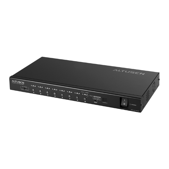
Page 15: Components
Chapter 1. Introduction Components Front View Item Description Port LEDs The Port LEDs provide status information about their corresponding AC outlet ports. There is one pair of LEDs for each port. The one on the left is the Remote Access LED; the one on the right is the Power LED: A Remote Access LED lights GREEN to indicate that the device attached to its corresponding port is capable of being controlled... - Page 16 PN0108 User Manual (Continued from previous page.) Item Description Power Each button (A to H), controls the power status of its Control corresponding AC output port as follows: Buttons Pressing the button for less than 3 seconds toggles the port between Remote Access enabled and Remote Access disabled (Local Mode).
-
Page 17: Rear View
Chapter 1. Introduction Rear View Item Description Power The power cable from the AC source plugs in here. Socket Circuit Press to reset the circuit. Breaker AC Power The power cables that connect to the computers plug in here. Outlets Safe Provides safe shutdown and rebooting for Windows 98SE, ME, Shutdown... - Page 18 PN0108 User Manual This Page Intentionally Left Blank...
-
Page 19: Chapter 2. Hardware Setup
Chapter 2 Hardware Setup Before You Begin 1. Important safety information regarding the placement of this device is provided on page 61. Please review it before proceeding. 2. Make sure that power to all the devices you will be connecting up have been turned off. -
Page 20: Rack Mounting
PN0108 User Manual Rack Mounting The PN0108 can be installed in most standard 19" (1U) racks. To rack mount the unit do the following: 1. Use the screws supplied with your rack mounting kit to attach the rack mounting brackets to each side of the device: Phillips Hex Head M3 x 8 Note: The unit can be installed either at the front or the back of the rack. -
Page 21: Single Stage Installation
Chapter 2. Hardware Setup Single Stage Installation In a Single Stage installation, there are no additional PN0108 Stations daisy chained down from the first unit. To set up a single stage installation, refer to the installation diagram on the next page (the numbers in the diagram correspond to the numbered steps), and do the following: 1. - Page 22 PN0108 User Manual Single Stage Installation Diagram PN0108 CN-6000...
-
Page 23: Daisy Chaining
Chapter 2. Hardware Setup Daisy Chaining To manage even more devices, up to 15 additional PN0108 Stations can be daisy chained down from the top level unit. Up to 128 devices can be managed on a complete installation. To set up a daisy chained installation do the following: 1. - Page 24 PN0108 User Manual This Page Intentionally Left Blank...
-
Page 25: Logging In
Overview Depending on your installation's components, the PN0108 can be accessed in various ways: via a browser connection to an ATEN/ALTUSEN internet enabled KVM switch (see Supported Devices, page 69 for a list of supported switches); a browser connection to a PN9108 or SN0108/SN0116; or from a local computer using a terminal program (such as Hyperterminal);... - Page 26 PN0108 User Manual 2. When the Security Alert dialog box appears, accept the certificate – it can be trusted. (See Trusted Certificates, page 71, for details.) The Login page appears: 3. Provide a valid Username and Password (set by the CN-6000 administrator), then Click Login to continue.
- Page 27 Chapter 3. Logging In 5. A File Download dialog box comes up asking what you want to do with the PowerMan.jar file. You can either run it from your browser (click Open), or save it to disk and run it from your computer. If your browser permits, run it from your browser.
-
Page 28: Pn9108 Browser Operation
PN0108 User Manual PN9108 Browser Operation Logging In Remote operation of the PN0108 via a PN9108 is browser based. It involves logging into the PN9108's web page, and selecting the PN0108 from the PN9108's Device Selector list. Note: The browser must support 128 bit SSL encryption. 1. -
Page 29: The Pn9108 Main Screen
Chapter 3. Logging In The PN9108 Main Screen After you have successfully logged in, the PN9108 Main Screen appears: Select the PN0108 that you want to access from the PN9108's Device Selector list. PN0108 operating procedures are discussed in Chapter 4, Operation. -
Page 30: Sn0108 / Sn0116 Browser Operation
PN0108 User Manual SN0108 / SN0116 Browser Operation Logging In Remote operation of the PN0108 via a SN0108 / SN0116 is browser based. The first step involves logging into the SN0108 / SN0116's web page, as follows: Note: 1. The browser must support 128 bit SSL encryption. 2. -
Page 31: The Sn0108 / Sn0116 Main Screen
Chapter 3. Logging In The SN0108 / SN0116 Main Screen After you have successfully logged in, the SN0108 / SN0116 Main Screen appears: The PN0108 is accessed through the Telnet function. (Continues on next page.) - Page 32 PN0108 User Manual (Continued from previous page.) 1. Click the Telnet button to bring up the Telnet Selection screen: 2. Select the port that the PN0108 is connected to. Note: 1. You must have permission in order to access a port. Port permission is set by the SN0108 / SN0116 administrator.
- Page 33 Chapter 3. Logging In 3. Click Connect. The SN0108 / SN0116 opens a Telnet session and a screen similar to the one below appears: 4. Log in with your SN0108 / SN0116 Username and Password. A telnet connection to the device is established:...
- Page 34 PN0108 User Manual 5. At the telnet prompt, key in: ??? to bring up the PN0108's menu: Select 1 to switch to the PN0108 configuration and control functions. These are the text based equivalents of the browser configuration and control functions. The descriptions and explanations for the Browser Operations discussed in Chapter 4, Operation, apply to the functions presented here, as well.
-
Page 35: Local Console Operation
Chapter 3. Logging In Local Console Operation Local console operation can be accomplished through a VT100 terminal program, such as Hyperterminal, or with the Java application supplied on the software CD that came with this package. Hyperterminal 1. Use the PON cable that came with this package to connect a COM port on the PC to the PN0108's RS-232 port. - Page 36 PN0108 User Manual 3. Key a name to describe the connection in the Name field (we used Com1Test); select an icon to represent the connection; then click OK. Note: In the examples that follow we use COM1. If you use a different COM port, change the settings accordingly.
- Page 37 Chapter 3. Logging In 5. The PN0108's serial port settings and the computer's COM port settings must be the same. Change the settings in your dialog box (if necessary), so that they match the PN0108's COM Port settings, then click OK. Note: The PN0108's default settings are 38400 bps;...
- Page 38 PN0108 User Manual 8. Change the settings (if necessary), so that they match the settings shown in the diagram, then click OK. 9. Close the HyperTerminal Window. When Windows asks if you want to disconnect, click Yes. When Windows asks if you want to save the session, click Yes.
-
Page 39: Java Application
Chapter 3. Logging In Java Application To use this application you must have the Java Runtime Environment (JRE) version 1.4.0 or higher installed on the computer that connects to the PN0108. If you don't already have the proper version of Java installed, go to the Java Sun website to download and install the latest JRE. - Page 40 PN0108 User Manual Running the Application: 1. Use the PON cable that came with this package to connect a COM port on the PC to the PN0108's RS-232 port. (Refer back to the installation diagram on page 12, if necessary.) 2.
-
Page 41: The Pn0108 Main Screen
Chapter 4 Operation The PN0108 Main Screen After you have successfully logged in, the PN0108 Main Screen appears: When you first start up, the Power Status & Control screen of the First Station appears in the large central panel. The power management operations for the devices attached to the Station's outlets are made here. -
Page 42: Device Selector
PN0108 User Manual Device Selector Since up to 16 PN0108 Stations can be daisy chained, this panel lists each of the Stations on your installation. The number in brackets, to the right of the title, indicates the total number of stations on the installation. -
Page 43: The Power Status Screen
Chapter 4. Operation The Power Status Screen The Top Panel Power Sockets: The top panel of the Power Status screen is divided into eight subareas which correspond to the A- H outlets on the PN0108's rear panel. Each subarea is composed of a socket icon that functions as the Power Button for its corresponding outlet, and an information panel to its right. - Page 44 PN0108 User Manual If Reboot is enabled (by putting a check in the checkbox), the computer attached to the Outlet's corresponding port will reboot instead of shutting off when the Power Button is clicked to turn the outlet off. This selection is disabled (grayed out) if the Outlet isn't configured for a Safe Shutdown capable option.
-
Page 45: The Bottom Panel
Chapter 4. Operation The Bottom Panel The bottom panel allows you to control the power status of your outlet groups. Outlets can be placed into groups so that Power On/Off actions can be carried out on the entire outlet group at the same time, rather than performing the same action on each outlet individually. - Page 46 PN0108 User Manual This Page Intentionally Left Blank...
-
Page 47: System Setup
Chapter 5 Administration System Setup Clicking the System button brings up the System dialog box: Administrator This section sets the administrator's login name and password. For security purposes, we strongly recommend you change the default value to something unique. The minimum number of alphanumeric characters for both entries is 4; the maximum number is 15. - Page 48 PN0108 User Manual Device Control The Device Control panel allows the PN0108 administrator to configure the PN0108's power management parameters. The functions provided by each of the buttons are explained in the sections that follow. Note: On multi-station installations, you must perform a separate set up for each of the Stations.
-
Page 49: Outlet Configuration
Chapter 5. Administration Outlet Configuration: The top panel allows you to set up a power management configuration for each outlet. These settings determine what takes place when you click the Power Button On or Off. The meanings of the field headings are given in the following table: Heading Meaning... - Page 50 PN0108 User Manual (Continued from previous page.) Heading Meaning Kill the Power If this option is selected, the PN0108 waits for the amount time set in the Power Off Delay field (see below), and then turns the Outlet's power OFF when its Power Button is clicked to turn off the power.
- Page 51 Chapter 5. Administration Outlet Groups: Outlet groups allow power control actions to be carried out on the entire group at the same time, rather than repeatedly performing the same action on each individual outlet. You can have four outlet groups per station, and each group can be given a distinctive name.
- Page 52 PN0108 User Manual Schedule The Schedule dialog box allows you to set up a scheduled Power On/Off configuration for each of the outlets. To do so: 1. Select your outlet from the buttons in the upper panel. 2. Put a check in the Enable/Disable checkbox to enable scheduling for the desired day.
-
Page 53: User Management
Chapter 5. Administration User Management The User Manager dialog box allows the Administrator to set up Usernames and Passwords that operators must provide in order to log into the PN0108. The minimum number of characters for each field is 4; the maximum is 15. The Administrator also uses this dialog box to set the outlets that a User can control. - Page 54 PN0108 User Manual Monitor The Device Monitor displays the power status of your entire installation. You can see at a glance what the On/Off status of each outlet is. Note: If the No timeout on monitoring function is enabled in the System dialog box (see System Setup, page 37), the PN0108 will not time out when this function is being used.
- Page 55 Chapter 5. Administration The PN0108 maintains a log file of the last 100 events that took place on it. This dialog box allows you to select the range of events you wish to view: Choose Today then click OK to see a listing of only today's events. Choose All then click OK to see a listing of events for the entire log file.
- Page 56 PN0108 User Manual Once you make a choice and click OK an Event Log List, similar to the one below, appears: When you have finished viewing the event list: If you want to return to the Event Log dialog box, click Back. If you want to erase the contents of the entire log file, click Clear All.
-
Page 57: Bios Power Management Settings
Chapter 6 Safe Shutdown and Reboot Overview The PN0108's Safe Shutdown and Reboot functions are available for systems running Windows. Safe shutdown and reboot lets you safely close a system down and reboot it without involving the danger to the file systems that simply killing the power supply does. -
Page 58: Automated Setup
PN0108 User Manual 4. The wording for the System after AC back function may vary somewhat from system to system. For example: AC Loss Auto Restart Restore on AC Power Loss In the BIOS settings, choose Power On (Full On). 5. - Page 59 Chapter 6. Safe Shutdown and Reboot By default, PMonitor monitors the COM1 port. If the utility displays an error message stating that it is unable to open the COM1 port, it means that the port is already being used by another utility. You can either stop the other utility, and try again, or use a different COM port for the PMonitor program.
-
Page 60: Manual Setup
PN0108 User Manual Manual Setup Windows NT, 2000, XP, and Server 2003 can be manually configured for safe shutdown and rebooting instead of using the Power Monitor utility. The following sections explain the procedures involved. Windows 2000 / XP / Server 2003: To set up Windows 2000, XP, or Server 2003 for safe shutdown and rebooting, do the following: 1. - Page 61 Chapter 6. Safe Shutdown and Reboot 2. Click Next. A dialog box similar to the one below appears: Select the options in the dialog box so that they match the settings shown in the figure above. 3. Click Finish; click OK. To check that the setup is working: 1.
- Page 62 PN0108 User Manual 1. Go to the Control Panel; open the UPS entry. A dialog box similar to the one below appears: a) For the COM port entry, select the COM port on the computer that the Safe Shutdown Cable is plugged into. b) Match the other options to the values shown in the figure above.
-
Page 63: Upgrading The Firmware
Chapter 7 Upgrading The Firmware The Windows-based Firmware Upgrade Utility (FWUpgrade.exe) provides a smooth, automated process for upgrading the PN0108's firmware. The Utility comes as part of a Firmware Upgrade Package that is specific for each device. New firmware upgrade packages are posted on our web site as they become available. - Page 64 PN0108 User Manual 4. Slide the First Station's Firmware Upgrade switch to the RECOVER position. a) Its Port LEDs blink at half second intervals. b) The STATION ID LEDs display the word, UP, and blink at half second intervals. 5. Slide the First Station's Firmware Upgrade switch back to the NORMAL position.
-
Page 65: Starting The Upgrade
Chapter 7. Upgrading The Firmware Starting the Upgrade To upgrade your firmware: 1. Run the downloaded Firmware Upgrade Package file - either by double clicking the file icon, or by opening a command line and entering the full path to it. The Firmware Upgrade Utility Welcome screen appears: 2. - Page 66 PN0108 User Manual 3. Click Next to continue. The Firmware Upgrade Utility main screen appears. The Utility inspects your installation. All the devices capable of being upgraded by the package are listed in the Device List panel. A blue background behind the device name indicates that it is ready to be upgraded.
- Page 67 Chapter 7. Upgrading The Firmware If you didn't enable Check Firmware Version, the Utility installs the upgrade files without checking whether they are a higher level, or not. As the Upgrade proceeds status messages appear in the Status Messages panel, and the progress toward completion is shown on the Progress bar.
-
Page 68: Upgrade Succeeded
PN0108 User Manual Upgrade Succeeded After the upgrade has completed, a screen appears to inform you that the procedure was successful: Click Finish to close the Firmware Upgrade Utility. Note: On a daisy chained installation, all stations restart automatically after they have been successfully upgraded. -
Page 69: Upgrade Failed
Chapter 7. Upgrading The Firmware Upgrade Failed If the upgrade failed to complete successfully a dialog box appears asking if you want to retry. Click Yes to retry. If you Click No, the Upgrade Failed screen appears: Click Cancel to close the Firmware Upgrade Utility. See the next section, Firmware Upgrade Recovery, for how to proceed. -
Page 70: Firmware Upgrade Recovery
PN0108 User Manual Firmware Upgrade Recovery Single Station Recovery To perform a firmware upgrade recovery, do the following: 1. Power the PN0108 OFF. 2. Slide the Firmware Upgrade switch to the RECOVER position. 3. Power the PN0108 back ON. 4. Repeat the upgrade procedure from the beginning. 5. -
Page 71: Appendix
Appendix Safety Instructions General Read all of these instructions. Save them for future reference. Follow all warnings and instructions marked on the device. Do not place the device on any unstable surface (cart, stand, table, etc.). If the device falls, serious damage will result. Do not use the device near water. - Page 72 PN0108 User Manual To help protect your system from sudden, transient increases and decreases in electrical power, use a surge suppressor, line conditioner, or uninterruptible power supply (UPS). Position system cables and power cables carefully; Be sure that nothing rests on any cables. When connecting or disconnecting power to hot pluggable power supplies, observe the following guidelines: Install the power supply before connecting the power cable to the power...
-
Page 73: Rack Mounting
Appendix Rack Mounting Before working on the rack, make sure that the stabilizers are secured to the rack, extended to the floor, and that the full weight of the rack rests on the floor. Install front and side stabilizers on a single rack or front stabilizers for joined multiple racks before working on the rack. -
Page 74: Power Cords
PN0108 User Manual Power Cords Use the cables supplied with this package. If it becomes necessary to replace the cables supplied with this package, be sure to use cables of at least the same standard as the ones provided. Power Cord: For models with a 220 - 240 V AC power supply, use a tandem (T blade) type attachment plug with ground connector power cord that meets the respective European country's safety regulations, such as VDE for Germany. -
Page 75: Technical Support
Online Technical Support http://support.aten.com Support Troubleshooting http://www.aten.com Documentation Software Updates Telephone Support 886-2-8692-6959 North America Email Support ATEN TECH support@aten-usa.com ATEN NJ sales@aten.com Online Technical Support ATEN TECH http://www.aten-usa.com/support Support ATEN NJ http://support.aten.com Troubleshooting ATEN TECH http://www.aten-usa.com Documentation ATEN NJ http://www.aten.com... -
Page 76: Troubleshooting
PN0108 User Manual Troubleshooting Overview Operation problems can be due to a variety of causes. The first step in solving them is to make sure that all cables are securely attached and seated completely in their sockets. In addition, updating the product’s firmware may solve problems that have been discovered and resolved since the prior version was released. -
Page 77: Problem 2
Appendix Problem 2: The computer has an older mainboard that doesn't support APM in the BIOS. What can I do to get Safe Shutdown and Reboot working? Solution: If you are running Windows 2000, XP, or Server 2003, you can do the following: 1. -
Page 78: Solution
PN0108 User Manual Problem 5: Although I have enabled Modem Ring Resume, the computers won’t restart. Solution: 1. Make sure you have enabled Modem Ring Resume in the computer’s BIOS settings. 2. If Modem Ring Resume has been enabled in the computer’s BIOS, check your mainboard manual to make sure it supports external modem wakeup. -
Page 79: Supported Devices
Appendix Supported Devices The following is a list of supported devices that can be used with the PN0108. CN6000 KN2108 / KN2116 KN9116 PN9108 SN0108 / SN0116... -
Page 80: Administrator Login Failure
PN0108 User Manual Administrator Login Failure If you are unable to perform an Administrator login (because the Username and Password information has become corrupted, or you have forgotten it, for example), you can clear the login information with the following procedure: 1. -
Page 81: Trusted Certificates
Appendix Trusted Certificates Overview When you try to log in to the device from your browser, a Security Alert message appears to inform you that the device’s certificate is not trusted, and asks if you want to proceed. The certificate can be trusted, but the alert is triggered because the certificate’s name is not found on Microsoft list of Trusted Authorities. -
Page 82: Installing The Certificate
PN0108 User Manual Installing the Certificate To install the certificate, do the following: 1. In the Security Alert dialog box, click View Certificate. The Certificate Information dialog box appears: Note: There is a red and white X logo over the certificate to indicate that it is not trusted. -
Page 83: Certificate Trusted
Appendix 5. Next, click Finish to complete the installation; then click OK to close the dialog box. Certificate Trusted The certificate is now trusted: When you click View Certificate, you can see that the red and white X logo is no longer present –... -
Page 84: Specifications
PN0108 User Manual Specifications Function Specification Power Inlets 1 x IEC 60320/C14 (M) Power Outlets 8 x IEC 60320/C13 (F) LEDs Outlet Power 8 (orange) Remote Access 8 (green) Station ID 2 x 7 segment (yellow) Connectors PON In 1 x DB-9 (F) PON Out 1 x DB-9 (M) Safe Shutdown... -
Page 85: Limited Warranty
Appendix Limited Warranty ATEN warrants this product against defects in material or workmanship for a period of one (1) year from the date of purchase. If this product proves to be defective, contact ATEN's support department for repair or replacement of your unit. ATEN will not issue a refund. Return requests can not be processed without the original proof of purchase. - Page 86 PN0108 User Manual This Page Intentionally Left Blank...
-
Page 87: Configuration
Index Single stage, 11 Administration, 37 Administrator Login Failure, 70 LEDs Port, 5 Log, 45 BIOS Logging in, 18, 20 Power Management, 47 CN6000, 15 Login failure, 70 Components Front view, 5 Main Screen, 31 Rear view, 7 PN9108, 19 Corrupt Password, 70 SN0108/SN0116, 21 Modem Ring Resume, 68... - Page 88 SJ/T 11364-2006, ii Stacking, 9 Rack Mounting, 10 Supported KVM switches, 69 Rack mounting, 10 System after AC Back, 68 Requirements, 4 RoHS, ii Technical Support, 65 Telephone support, iii Safety Instructions Trusted Certificates, 71 General, 61 Rack Mounting, 63 Schedule, 42 User management, 43 Single stage installation, 11...
- Page 89 PN0108 User Manual Contents FCC Information ..........ii SJ/T 11364-2006.
-
Page 90: Automated Setup
PN0108 User Manual Local Console Operation ........25 Hyperterminal . -
Page 91: Starting The Upgrade
PN0108 User Manual Chapter 7. Upgrading The Firmware Preparation ..........53 Starting the Upgrade . - Page 92 PN0108 User Manual...
Need help?
Do you have a question about the ALTUSEN PN0108 and is the answer not in the manual?
Questions and answers