Table of Contents
Advertisement
Quick Links
Download this manual
See also:
User Manual
Advertisement
Table of Contents

Related Manuals for ATEN Altusen KN1108v


Summary of Contents for ATEN Altusen KN1108v
- Page 1 KVM Over the NET™ KN1108v / KN1116v User Manual www.aten.com...
-
Page 2: Sj/T 11364-2006
KVM Over the NET™ User Manual FCC Information This is an FCC Class A product. In a domestic environment this product may cause radio interference in which case the user may be required to take adequate measures. This equipment has been tested and found to comply with the limits for a Class A digital device, pursuant to Part 15 of the FCC Rules. -
Page 3: User Information
86-10-5255-0110 Japan 81-3-5615-5811 Korea 82-2-467-6789 North America 1-888-999-ATEN ext 4988 United Kingdom 44-8-4481-58923 User Notice All information, documentation, and specifications contained in this manual are subject to change without prior notification by the manufacturer. The manufacturer makes no representations or warranties, either expressed or implied, with respect to the contents hereof and specifically disclaims any warranties as to merchantability or fitness for any particular purpose. -
Page 4: Package Contents
Copyright © 2013 ATEN® International Co., Ltd. F/W Version: v1.0.066 Manual Date: 2013-01-16 Altusen and the Altusen logo are registered trademarks of ATEN International Co., Ltd. All rights reserved. All other brand names and trademarks are the registered property of their respective owners. -
Page 5: Table Of Contents
KN1108v Front View ........ - Page 6 KVM Over the NET™ User Manual Two Stage Installation Diagram ......24 Hot Plugging .
- Page 7 KVM Over the NET™ User Manual Mounting Virtual Media ....... . . 69 Zoom .
- Page 8 KVM Over the NET™ User Manual Adding a Favorite ........105 Modifying a Favorite .
- Page 9 KVM Over the NET™ User Manual Finishing Up......... 148 ANMS .
- Page 10 KVM Over the NET™ User Manual Backup ..........185 Restore .
- Page 11 KVM Over the NET™ User Manual North America ......... . 212 Specifications (English).
- Page 12 KVM Over the NET™ User Manual Virtual Media Support ........249 WinClient ActiveX Viewer / WinClient AP .
-
Page 13: About This Manual
KVM Over the NET™ User Manual About This Manual This User Manual is provided to help you get the most from your KVM Over the NET™ switch system. It covers all aspects of installation, configuration and operation. An overview of the information found in the manual is provided below. -
Page 14: Conventions
KVM Over the NET™ User Manual Chapter 12, Port Operation, provides detailed information on accessing and operating the devices connected to the KVM Over the NET™ switch’s ports. Chapter 13, The Log Server, explains how to install and configure the Log Server. -
Page 15: Terminology
For information about all ALTUSEN products and how they can help you connect without limits, visit ALTUSEN on the Web or contact an ALTUSEN Authorized Reseller. Visit ALTUSEN on the Web for a list of locations and telephone numbers: International http://www.aten.com North America http://www.aten-usa.com... -
Page 16: Chapter 1 Introduction
Chapter 1 Introduction Overview The KN1108v / KN1116v is an IP-based KVM control unit, with dual IP / dual power functionality, serial console access, and Virtual Media support, that allows both local and remote operators to monitor and access multiple servers from a single console. - Page 17 In addition, the KN1108v / KN1116v offers dual IP and dual power supplies so that if one of the IP or power supplies fails, the second automatically takes over.
-
Page 18: Features
KVM Over the NET™ User Manual Features Hardware High port density – RJ-45 connectors for up to 8/16 ports in a 1U housing One bus for remote KVM over IP access Two 10/100/1000 Mbps NICs for redundant LAN or dual IP operation Dual power supplies provide backup, redundancy and reliability Supports PS/2, USB, Sun Legacy (13W3), serial (RS-232) connectivity Blade server support... -
Page 19: Ease-To-Use Interface
Chapter 1. Introduction Ease-to-Use Interface Local Console, Browser, and AP GUIs offer a unified multilanguage interface to minimize user training time and increase productivity Multiplatform client support (Windows, Mac OS X, Linux, Sun) Multibrowser support (IE, Mozilla, Firefox, Safari, Opera, Netscape) Browser-based UI in pure Web technology allows administrators to perform administrative tasks without the need for Java to be pre-installed User can launch multiple Virtual Remote Desktops to control multiple... -
Page 20: Virtual Media
KVM Over the NET™ User Manual Virtual Media Virtual media enables file applications, OS patching, software installation and diagnostic testing Works with USB enabled servers at the operating system and BIOS level Supports DVD/CD drives, USB mass storage devices, PC hard drives and ISO images Virtual Remote Desktop Video quality and video tolerance can be adjusted to optimize data transfer... -
Page 21: System Requirements
Chapter 1. Introduction System Requirements Remote User Computers Remote user computers (also referred to as client computers) are the ones the users log into the switch with from remote locations over the internet (see Terminology, page xv). The following equipment must be installed on these computers: For best results we recommend computers with at least a P 4 2 GHz processor, with their screen resolution set to 1024 x 768. -
Page 22: Kvm Adapter Cables
KVM Over the NET™ User Manual KVM Adapter Cables Cat 5e (or higher) cable is required to connect the KN1108v / KN1116v to the KVM Adapter Cables (see page 19). The following KVM Adapter Cables are required for use with the... -
Page 23: Operating Systems
Solaris 8 and higher Novell Netware 5.0 and higher OS 9 and higher* 6.2 and higher Browsers Supported browsers for users that log into the KN1108v / KN1116v include the following: Browser Version 6 and higher Chrome 8.0 and higher... -
Page 24: Components
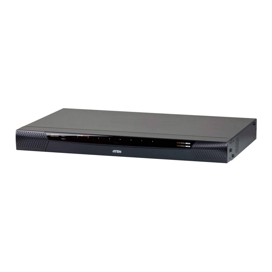
KVM Over the NET™ User Manual Components KN1108v Front View KN1116v Front View... - Page 25 Chapter 1. Introduction Component Description Power LED Lights when the unit is powered up and ready to operate. Port LEDs The Port LEDs provide status information about their corresponding KVM Ports. GREEN: The computer attached to the port is On Line. RED: The computer attached to the port is Selected (has KVM focus).
-
Page 26: Kn1108V Front View
KVM Over the NET™ User Manual KN1108v Front View KN1116v Rear View... - Page 27 Chapter 1. Introduction Component Description Power Sockets The power cables plug in here. Power This standard slide switch powers the unit on and off. Switches PON Port This connector is provided for a Power over the Net™ (PON) unit which allows servers attached to the KVM Over the NET™...
-
Page 28: Chapter 2. Hardware Setup
Chapter 2 Hardware Setup Overview For convenience and flexibility that allows mixing the PS/2 and USB interfaces, as well as multiple platforms, the KVM Over the NET™ switch design utilizes KVM Adapter Cables, that serve as intermediaries between the switch and the connected devices (refer to the installation diagram on p. 16). A separate KVM Adapter Cable is required for each server or device connection. -
Page 29: Stacking And Rack Mounting
Chapter 2. Hardware Setup Stacking and Rack Mounting The KVM Over the NET™ switch can be stacked on the desktop or rack mounted in a variety of ways. The following sections take you through the procedures for each method. Stacking The KVM Over the NET™... -
Page 30: Rack Mounting
KVM Over the NET™ User Manual Rack Mounting The KVM Over the NET™ switch can be mounted in a 19" (1U) rack. The mounting brackets can screw into either the front or the back of the unit so that it can attach to the front or the back of the rack. Rack Mounting - Front To mount the unit at the front of the rack, do the following: 1. - Page 31 Chapter 2. Hardware Setup 3. Position the device in the front of the rack and align the holes in the mounting brackets with the holes in the rack. 4. Screw the mounting brackets to the rack. Note: Cage nuts are provided for racks that are not pre-threaded.
-
Page 32: Rack Mounting - Rear
KVM Over the NET™ User Manual Rack Mounting - Rear To mount the unit at the rear of the rack, do the following: 1. Remove the two screws at the rear of the unit. Phillips head hex M3 x 6 2. - Page 33 Chapter 2. Hardware Setup 4. Screw the mounting brackets to the rear of the rack. Note: Cage nuts are provided for racks that are not pre-threaded.
-
Page 34: Single Stage Installation
3. The KN1108v / KN1116v does not support distances that exceed 20m between itself and the local monitor. 2. If you are using a laptop USB console to control the KN1108v / KN1116v locally, use a mini-USB cable to connect the laptop to the KN1108v / KN1116v’s Laptop port, located on the unit’s front panel. - Page 35 PN0108, be sure to use the utility power cords supplied with your package instead of standard power cords. After the KN1108v / KN1116v is cabled up you can turn on the power. After it is powered up, you can turn on the servers.
-
Page 36: Single Stage Installation Diagram
KVM Over the NET™ User Manual Single Stage Installation Diagram PN0108 Modem... -
Page 37: Adapter Cable Connection Diagram
Chapter 2. Hardware Setup Adapter Cable Connection Diagram KA7120 / KA9120 KA7177 KA7170 / KA9170 KA7130 / KA9130 KA7140 KA9140 SERIAL TERMINAL KA7175 KA7176... -
Page 38: Two Stage Installation
Two Stage Installation To control even more servers, up to 16 additional KVM switches can be cascaded from the KVM ports of the original KN1108v / KN1116v. As many as 256 servers can be controlled in a complete two stage installation. -
Page 39: Two Stage Installation Diagram
Chapter 2. Hardware Setup Two Stage Installation Diagram KN1108v KH1516 KA9120... -
Page 40: Hot Plugging
See Sidebar Utilities, page 84 for port configuration details. Powering Off and Restarting If it becomes necessary to power off the KN1108v / KN1116v, or if the switch loses power and needs to be restarted, wait 10 seconds before powering it back on. -
Page 41: Port Id Numbering
Chapter 2. Hardware Setup Port ID Numbering Each server on the installation is assigned a unique Port ID. Its Port ID is a one or two segment number that is determined as follows: A server attached to a First Stage unit has a one segment Port ID (from 1– 8/16) that corresponds to the KVM Port number that it is connected to. -
Page 42: Super Administrator Setup
Super Administrator Setup Overview This chapter discusses the administrative procedures that the Super Administrator performs to get the KN1108v / KN1116v set up for the first time. First Time Setup Once the KN1108v / KN1116v has been cabled up, the Super Administrator needs to set the unit up for user operation. - Page 43 Chapter 3. Super Administrator Setup After you successfully log in, the Main Page appears:...
-
Page 44: Network Setup
KVM Over the NET™ User Manual Network Setup To set up the network, do the following: 1. Click the Device Management tab. 2. Select the Network tab. 3. Fill in the fields according to the information provided under Network, page 144. -
Page 45: Changing The Super Administrator Login
Chapter 3. Super Administrator Setup Changing the Super Administrator Login To change the default Super Administrator Username and Password, do the following: 1. At the top of the screen, click the User Management tab. The User Management page has a list of Users and Groups in the Sidebar at the left, and a more detailed list of users –... - Page 46 KVM Over the NET™ User Manual The User Information page appears: 3. Change the Username and Password to something unique. 4. Enter the password again in the Confirm Password field to confirm it is correct. 5. Click Save. 6. When the dialog box informing you that the change completed successfully appears, Click OK.
-
Page 47: Moving On
Windows Client AP; and the stand-alone Java Client AP. Choose the approach that suits you best. Note: Firmware Upgrade Maintenance cannot be performed from the local console. You must log in remotely with one of the KN1108v / KN116v’s other GUI utilities for this operation. -
Page 48: Chapter 4 Logging In
Local Console Login When the local console is attached (see Single Stage Installation, page 19) and there is no user logged in, the KN1108v / KN1116v login screen appears on the monitor: Simply key in your valid Username and Password, then click Login to bring... - Page 49 Chapter 4. Logging In The Local Console Main Page is similar to the Web Browser, WinClient and Java Client Main Pages. For a description of the Web Browser Main Page, see page 43.
-
Page 50: Browser Login
KVM Over the NET™ User Manual Browser Login KN1108v / KN1116v switches can be accessed via an Internet browser running on any platform. To access the switch, do the following: 1. Open the browser and specify the IP address of the switch you want to access in the browser's location bar. -
Page 51: Windows Client Ap Login
(although you initially download the Windows AP Client program from the browser page – see Chapter 11, Download). To connect to the KN1108v / KN1116v, go to the location on your hard disk that you downloaded the Windows AP Client program to, and double-click its... -
Page 52: The Windows Client Ap Connection Screen
Server List window. Server This area is used when you want to connect to a KN1108v / KN1116v at a remote location. You can drop down the IP list box and select an address from the list. If the address you want isn't listed, you can key in the target IP address in the IP field, and its port number in the Port field. -
Page 53: Connecting - Windows Client Ap
Chapter 4. Logging In Connecting – Windows Client AP To connect to a KN1108v / KN1116v do the following:: 1. From the Server List box, double-click the device that you wish to connect to. – Or – Specify its IP address and port number in the Server IP and Port input boxes. -
Page 54: The File Menu
KVM Over the NET™ User Manual The File Menu The File Menu allows the operator to Create, Save, and Open user created Work files. A Work File consists of all the information specified in a Client session. This includes the Server List and Server IP list items, as well as the Hotkey settings. -
Page 55: Java Client Ap Login
(although you initially download the Java AP Client program from the browser page – see Chapter 11, Download). To connect to the KN1108v / KN1116v, go to the location on your hard disk that you downloaded the Java AP Client program to, and double-click its icon... -
Page 56: The Java Client Ap Connection Screen
Server List window. Server This area is used when you want to connect to a KN1108v / KN1116v at a remote location. You can drop down the IP list box and select an address from the list. If the address you want isn't listed, you can key in the target IP address in the IP field, and its port number in the Port field. -
Page 57: Connecting - Java Client Ap
Chapter 4. Logging In Connecting – Java Client AP To connect to a KN1108v / KN1116v do the following:: 1. From the Server List box, double-click the device that you wish to connect to. – Or – Specify its IP address and port number in the Server IP and Port input boxes. -
Page 58: Chapter 5. The User Interface
The User Interface Overview Once you have successfully logged in, the KN1108v / KN1116v user interface Main Page appears. The look of the page varies slightly, depending on which method you used to log in. Each of the interfaces is described in the sections that follow. -
Page 59: Page Components
About About provides information regarding the switch’s current firmware version. Logout Click this button to log out of your KN1108v / KN1116v session. Welcome Message If this function is enabled (see Welcome Message*, page 108), a welcome message displays here. -
Page 60: The Tab Bar
There are two small icons at the extreme right of the page. Their functions are described in the table, below: Icon Function Click this icon to brings up a panel with information about the KN1108v / KN1116v firmware version. Click this icon to log out and end your KN1108v / KN1116v session. -
Page 61: Laptop Usb Console Main Page
Chapter 5. The User Interface Laptop USB Console Main Page After connecting a laptop to the KN1108v / KN1116v’s Laptop port, logging in, and opening the AP, the Laptop USB Console main page appears: The look of the Laptop USB Console main page is the same as the AP GUI. -
Page 62: The Ap Gui Main Page
KVM Over the NET™ User Manual The AP GUI Main Page With WinClient AP, and Java Client AP access, once users log in (see Logging In, page 33), the GUI Main Page comes up: The GUI Main Page is similar to that of the Web Browser. The differences between them are as follows: 1. - Page 63 Chapter 5. The User Interface 4. There is an additional icon at the extreme right of the page: Click this icon to close the GUI Main Page and go to the display of the last selected port. 5. The GUI can be navigated via the keyboard as shown in the table, below: Keys Action Ctrl + P...
-
Page 64: The Local Console Gui Main Page
KVM Over the NET™ User Manual The Local Console GUI Main Page The Local Console GUI Main Page is similar to the Java and Windows AP GUI Main Page: The major difference is that the Local Console Main Page doesn’t have a tab for Download. -
Page 65: The Control Panel
Chapter 5. The User Interface The Control Panel WinClient Control Panel Since the WinClient Control Panel (for the ActiveX Web Viewer and WinClient AP) contains the most complete functionality, this section describes the WinClient Control Panel. Although the Java Control Panel (for the Web Viewer and Java Client AP) does not enable all of the features that this one does, the functions that they do share are the same, and you can refer to the information described here when using it. - Page 66 KVM Over the NET™ User Manual Right clicking in the text row area brings up a menu-style version of the toolbar. In addition, it allows you to select options for the Screen Mode, Zoom, Mouse Pointer type, and Mouse Sync Mode. These functions are discussed in the sections that follow.
-
Page 67: Winclient Control Panel Functions
Chapter 5. The User Interface WinClient Control Panel Functions The Control Panel functions are described in the table below. Icon Function This is a toggle. Click to make the Control Panel persistent – i.e., it always displays on top of other screen elements. Click again to have it display normally. - Page 68 Under an accessed port, click to begin Auto Scan Mode. The KN1108v / KN1116v automatically switches among the ports that were selected for Auto Scanning with the Filter function (see Filter, page 87). This allows you to monitor their activity without having to switch among them manually.
- Page 69 Chapter 5. The User Interface Click to bring up the Control Panel Configuration dialog box. See Control Panel Configuration, page 78, for details on configuring the Control Panel. Click to exit the viewer. Exiting from a Browser Viewer session brings you back to the web browser Main Page.
-
Page 70: Macros
KVM Over the NET™ User Manual Macros The Macros icon provides access to three functions found in the Macros dialog box: Hotkeys, User Macros, and System Macros. Each of these functions is described in the following sections. Hotkeys Various actions related to manipulating the remote server can be accomplished with hotkeys. - Page 71 Substitute Alt key Although all other keyboard input is captured and sent to the KN1108v / KN1116v, [Alt + Tab] and [Ctrl + Alt + Del] work on your local client computer. In order to implement their effects on the remote server, another key may be substituted for the Alt key.
-
Page 72: User Macros
KVM Over the NET™ User Manual User Macros User Macros are created to perform specific actions on the remote server. To create the macro, do the following: 1. Select User Macros, then click Add. 2. In the dialog box that comes up, replace the “New Macro” text with a name of your choice for the macro:... - Page 73 Chapter 5. The User Interface 3. Click Record. The dialog box disappears, and a small panel appears at the top left of the screen: 4. Press the keys for the macro. To pause macro recording, click Pause. To resume, click Pause again. Clicking Show brings up a dialog box that lists each keystroke that you make, together with the amount of time each one takes: Clicking Cancel cancels all keystrokes.
- Page 74 KVM Over the NET™ User Manual 6. If you haven’t brought up the Show dialog, click Done when you have finished recording your macro. You return to the Macros dialog box with your system macro key presses displayed in the Macro column: 7.
- Page 75 Chapter 5. The User Interface After creating your macros, you can run them in any of three ways: 1. By using the hotkey (if one was assigned). 2. By opening the Macro List on the Control Panel and clicking the one you want (see page 53).
-
Page 76: System Macros
KVM Over the NET™ User Manual Search Search, at the bottom of the dialog box, lets you filter the list of macros that appear in the large upper panel for you to play or edit. Click a radio button to choose whether you want to search by name or by key;... - Page 77 Chapter 5. The User Interface 3. Click Record. The dialog box disappears, and a small panel appears at the top left of the screen: 4. Press the keys for the macro. To pause macro recording, click Pause. To resume, click Pause again. Clicking Show brings up a dialog box that lists each keystroke that you make, together with the amount of time each one takes (see page 62).
- Page 78 KVM Over the NET™ User Manual 7. If you want to change any of the keystrokes, select the macro and click Edit. This brings up a dialog box similar to the one for Show. You can change the content of your keystrokes, change their order, etc. 8.
-
Page 79: Video Settings
Chapter 5. The User Interface Video Settings Clicking the Hammer icon on the Control Panel brings up the Video Settings dialog box. The options in this dialog box allow you to adjust the placement and picture quality of the remote screen on your monitor: The meanings of the video adjustment options are given in the table below. - Page 80 Depending on the network bandwidth, a high value may adversely effect response time. Enable Refresh The KN1108v / KN1116v can redraw the screen every 1 to 99 seconds, eliminating unwanted artifacts from the screen. Select Enable Refresh and enter a number from 1 through 99. The KN1108v / KN1116v will redraw the screen at the interval you specify.
-
Page 81: Gamma Adjustment
Chapter 5. The User Interface Gamma Adjustment If it is necessary to correct the gamma level for the remote video display, use the Gamma function of the Video Adjustment dialog box. Under Basic configuration, there are ten preset and four user-defined levels to choose from. -
Page 82: The Message Board
KVM Over the NET™ User Manual The Message Board The KN1108v / KN1116v supports multiple user logins, which may cause access conflicts. To alleviate the problem, a message board has been provided, which allows users to communicate with each other: Button Bar The buttons on the Button Bar are toggles. -
Page 83: Message Display Panel
Chapter 5. The User Interface Message Display Panel Messages that users post to the board - as well as system messages - display in this panel. If you disable Chat, however, messages that get posted to the board won't appear. Compose Panel Key in the messages that you want to post to the board in this panel. -
Page 84: Virtual Media
KVM Over the NET™ User Manual Virtual Media The Virtual Media feature allows a drive, folder, image file, removable disk, or smart card reader on a user’s system to appear and act as if it were installed on the remote server. Note: 1. - Page 85 Chapter 5. The User Interface 2. Click Add; then select the media source. Depending on your selection, additional dialog boxes appear to enable you to select the drive, file, folder, or removable disk you desire. See Virtual Media Support, page 249 for a list of supported virtual media types, and details about mounting them.
- Page 86 KVM Over the NET™ User Manual 6. To remove an entry from the list, select it and click Remove. 7. After you have made your media source selections, click Mount. The dialog box closes. The virtual media devices that you have selected are redirected to the remote server, where they show up as drives, files, folders, etc.
-
Page 87: Zoom
Chapter 5. The User Interface Zoom The Zoom icon controls the zoom factor for the remote view window. Settings are as follows: Setting Description 100% Sizes and displays the remote view window at 100%. Sizes and displays the remote view window at 75%. Sizes and displays the remote view window at 50%. -
Page 88: The On-Screen Keyboard
KVM Over the NET™ User Manual The On-Screen Keyboard The KN1108v / KN1116v supports an on-screen keyboard, available in multiple languages, with all the standard keys for each supported language. Click this icon to pop up the on-screen keyboard: One of the major advantages of the on-screen keyboard is that if the keyboard languages of the remote and local systems aren’t the same, you don’t have to... -
Page 89: Selecting Platforms
Chapter 5. The User Interface Selecting Platforms The On-screen Keyboard supports the Sun platform as well as the PC. To select the platform, do the following: 1. Click the down arrow next to the currently selected platform, to drop down the platform list. -
Page 90: Mouse Pointer Type
KVM Over the NET™ User Manual Mouse Pointer Type KN1108v / KN1116v switches offer a number of mouse pointer options when working in the remote display. Click this icon to select from the available choices: Note: 1. Before accessing a port, only Dual and Crosshairs are available for the Windows Viewers. -
Page 91: Mouse Dynasync Mode
Chapter 5. The User Interface Mouse DynaSync Mode Synchronization of the local and remote mouse pointers is accomplished either automatically or manually. Automatic Mouse Synchronization (DynaSync) Mouse DynaSync provides automatic locked-in synching of the remote and local mouse pointers – eliminating the need to constantly resync the two movements. -
Page 92: Mac And Linux Considerations
KVM Over the NET™ User Manual Mac and Linux Considerations For Mac OS versions 10.4.11 and higher, there is a second DynaSync setting to choose from. If the default Mouse DynaSync result is not satisfactory, try the Mac 2 setting. To select Mac 2, right click in the text →... -
Page 93: Control Panel Configuration
Chapter 5. The User Interface Control Panel Configuration Clicking the Control Panel icon brings up a dialog box that allows you to configure the items that appear on the Control Panel, as well as its graphical settings: The organization of the dialog box is described in the table, below: Item Description Customize... - Page 94 Control Panel as follows: Bus No./Total Users. (See the Control Panel diagram on page 50 for an example.) Snapshot These settings let the user configure the KN1108v / KN1116v screen capture parameters (see the Snapshot description under The Control Panel, page 50): Path lets you select a directory that the captured screens automatically get saved to.
-
Page 95: The Java Control Panel
Chapter 5. The User Interface The Java Control Panel The Java Applet Viewer and Java Client AP Control Panel is similar to the one used by the WinClient: The major differences between them are: In the Macros dialog box, Toggle Mouse Display is not available. The Dot mouse pointer type is not available. -
Page 96: Chapter 6 Port Access
Chapter 6 Port Access Overview When you log in to the switch the Port Access page comes up with the KN1108v / KN1116v KVM Connections page displayed. Browser GUI AP GUI... - Page 97 Sidebar at the left of the page. In addition to KN1108v / KN1116v listings, if any PON (Power Over the Net™) devices are connected to the switches they are listed separately below the switch listings.
-
Page 98: The Sidebar
KVM Over the NET™ User Manual The Sidebar All KVM switches, PON devices, and Blade Servers – including their ports and outlets – are listed in a tree structure in the Sidebar at the left of the screen: The Sidebar Tree Structure The characteristics of the Sidebar tree structure are the following: Users are only allowed to see the devices and ports/outlets that they have access permission for. -
Page 99: Sidebar Utilities
Chapter 6. Port Access Outlets that are On have their icons in Amber; the icons are Gray for outlets that are Off. To access and operate a port, double click its icon. Port operation details are discussed in Chapter 12, Port Operation. Note: 1. -
Page 100: Port/Outlet Naming
KVM Over the NET™ User Manual Port/Outlet Naming For convenience – especially in large installations with many devices, ports and outlets – administrators and users with port configuration permission, can give each port or outlet a name. To assign, modify or delete a name, do the following: 1. -
Page 101: Scan
Chapter 6. Port Access Scan Scan is found at the bottom of the AP GUI Sidebar. It automatically switches among all the ports that are visible in the Sidebar (see Filter, below), at regular intervals, so that their activity can be monitored automatically. See Auto Scanning, page 194 for details. -
Page 102: Filter
KVM Over the NET™ User Manual Filter Filter allows you to control the number and type of ports that display in the Sidebar, as well as which ports get scanned when Auto Scan and Array Modes are invoked (see Scan and Array, above). When you click Filter, the bottom of the panel changes to look similar to the image, below: The meanings of the choices are explained in the following table: Choices... -
Page 103: Kvm Devices And Ports - Connections Page
Chapter 6. Port Access KVM Devices and Ports – Connections Page For KVM Over the NET™ switches, the Connections page displays port status information at the device level, and port connection configuration options at the port level. Device Level When a KVM Over the NET™ switch is selected in the Sidebar, the Connections page displays a list of ports for the device that the user is authorized to access or view. -
Page 104: Port Level
KVM Over the NET™ User Manual Port Level When a port is selected in the Sidebar, the Connections page changes to display the port connection and configuration options: The screen is divided into two or three major panels, as described in the sections that follow. -
Page 105: Power Management
Chapter 6. Port Access Power Management If a PN0108 is connected to the KVM Over the NET™ switch, and a device is connected to one of the PN0108’s outlets, you can power manage (On, Off, Reboot) selected outlets directly from this page, instead of having to select them on the PON device, itself. -
Page 106: Com Ports - Connections Page
If you have serial devices connected to the KN1108v / KN1116v serial ports, these will appear as COM1 and COM 2 in the Sidebar tree. Note: Use Cat 5e cable to connect the KN1108v / KN1116v’s Serial ports to an SA0142 Adapter. Connect the Adapter’s serial connector to any generic serial device. -
Page 107: Port Property
Chapter 6. Port Access Port Property The Port Property page displays the current Status of the COM port, and allows you to configure the Properties, as described in the table below: Bits per This sets the port’s data transfer speed. Choices are from second 300—460800 (drop down the list to see them all). -
Page 108: Associated Link
KVM Over the NET™ User Manual Associated Link The Associated Link page allows to make the port associations: Click Add to bring up the dialog box to enter a port number; then click OK: The port number now appears as an Associated Link. To remove an Associated Link, select it in the list, then click Remove. -
Page 109: Accessing The Com Ports
Chapter 6. Port Access Accessing the COM Ports To access the device running on the COM port, double click on its entry in the sidebar to open the Remote View GUI, as shown below: The Remote View client has a control panel similar to the one described in the previous chapter (see The Control Panel, page 50), so you can reference this for descriptions of the toolbars function. -
Page 110: Pon Devices - Device Monitor Page
KVM Over the NET™ User Manual PON Devices – Device Monitor Page Power Over the Net™ (PON) devices that are connected to the switches display below the KVM switches in the Sidebar. When a PON device is selected in the Sidebar, the Device Monitor page appears: The Main Panel –... -
Page 111: Action Buttons
Chapter 6. Port Access PON View is the default page view, All PON devices and their outlets that are connected to the switch are listed under the Name column. Outlets that are synchronized or that belong to groups have a green power outlet icon in front of their names. -
Page 112: Outlet Groups
KVM Over the NET™ User Manual Outlet Groups To create outlet groups, do the following: 1. Select the outlets you want to include in the group. 2. Click Group. The Outlet Group dialog box comes up: 3. Select whether or not the outlets will belong to a new group or to an existing group. -
Page 113: The Main Panel - Group View
Chapter 6. Port Access The Main Panel – Group View Clicking the PON View button takes you back to the PON View page. To delete a group, select it in the main panel, then click Delete. Selecting a group in the main panel, then clicking Ungroup, removes all outlets from that group. -
Page 114: Outlet Settings
KVM Over the NET™ User Manual Outlet Settings When an outlet is selected in the Port Access page Sidebar, the Outlet Settings page appears: The Outlet Properties panel indicates the name of the PON that the outlet belongs to and the outlet’s name, as well as On, Off, and Reboot buttons to manually manage the outlet’s power. -
Page 115: Blade Servers - Connections Page
Chapter 6. Port Access Blade Servers – Connections Page Blade Servers that are connected to the switches display below the KVM switches and PON devices in the Sidebar. This section describes accessing and configuring the blade servers, and associating the blades with KVM switch ports. -
Page 116: Associating Ports
KVM Over the NET™ User Manual Associating Ports Main Panel Device View Port association begins by clicking the Blade Configuration menu item at the far right of the menu bar. The page comes up in Device View, listing all of the KVM switch’s ports, and the blade servers (IBM and Dell servers), or individual blades (HP servers) that have been associated with them: To make an association from the device view, you first select a KVM port, then... -
Page 117: Main Panel Blade View
Chapter 6. Port Access 4. Click Save. After the association completes successfully, the blade icon appears as the port indicator in the Sidebar tree. To access the device running on the blade, click on its entry in the Sidebar. Main Panel Blade View At the bottom of the Device View main panel is a button labeled Blade View. -
Page 118: Unassociating Ports
KVM Over the NET™ User Manual 3. In the screen that comes up, select the port that you want to associate it with. 4. Click Save. After the association completes successfully, the blade icon appears as the port indicator in the Sidebar tree. To access the device running on the blade, click on its entry in the Sidebar. -
Page 119: History
Chapter 6. Port Access History The History page provides a record of each time that a port was accessed. It provides quick access to the most recently used ports. You can access a port shown in the main panel by double clicking it. If there are more entries than there is room on the screen, a scroll bar appears to let you scroll up and down to see the entire record. -
Page 120: Favorites
KVM Over the NET™ User Manual Favorites The Favorites page is similar to a bookmarks feature. Ports that you frequently access can be saved in a list here. Simply open this page and select the port – rather than hunting for it in the Sidebar. This feature is especially handy on large, crowded installations: Adding a Favorite To add a port to the favorites, do the following:... -
Page 121: Modifying A Favorite
Chapter 6. Port Access 2. This will be a container to hold your port entries. Click inside the text entry box to erase Untitled Favorite and key in an appropriate name, then click on any empty space in the main panel. 3. -
Page 122: User Preferences
KVM Over the NET™ User Manual User Preferences The User Preferences page allows users to set up their own, individual, working environments. The switch stores a separate configuration record for each user profile, and sets up the working configuration according to the Username that was keyed into the Login dialog box: The page settings are explained in the following table: Setting... - Page 123 Chapter 6. Port Access Setting Function Scan Duration Determines how long the focus dwells on each port as it cycles through the selected ports in Auto Scan Mode (see Auto Scanning, page 194). Key in a value from 1—255 seconds. The default is 5 seconds;...
-
Page 124: Sessions
KVM Over the NET™ User Manual Sessions The Session page lets the administrator and users with User Management permissions see at a glance which users are currently logged into the KVM Over the NET™ switch, and provides information about each of their sessions. Note: 1. -
Page 125: Access
Chapter 6. Port Access Access Administrators use the Access page to set user and group access and configuration rights for switches and ports. Note: The Access page only appears for those users with User Management permissions. It isn’t available for other users. Device Level Browser GUI Interface If a switch is chosen in the Sidebar, the Main panel looks similar to the one shown below:... -
Page 126: Port Level Browser Gui Interface
KVM Over the NET™ User Manual Port Level Browser GUI Interface If a port is chosen in the Sidebar, the Main panel looks similar to the one shown below. The port access settings are explained in the following table: Name Each port accessible to the user is listed under the Names column. -
Page 127: Device Level Ap Gui Interface
Chapter 6. Port Access Device Level AP GUI Interface If a switch is chosen in the Sidebar, the Main panel looks similar to the one below: The page is essentially the same as the one for the Browser GUI (see page 110), with the exception that there are filters at the top of the columns. -
Page 128: Port Level Ap Gui Interface
KVM Over the NET™ User Manual Port Level AP GUI Interface If a port is chosen in the Sidebar, the Main panel looks similar to the one below: The page is essentially the same as the one for the Browser GUI (see page 111), with the exception that there are filters at the top of the columns. -
Page 129: Saving Changes
Chapter 6. Port Access Filter Description Mount All Users and Groups appear in the list. Full Access Only Users and Groups with Full Access Mount USB permissions appear in the list. Read Only Only Users and Groups with Read Only Mount USB permissions appear in the list. -
Page 130: Port Configuration
KVM Over the NET™ User Manual Port Configuration Device Level When a device is selected in the Sidebar, the only item available under Port Configuration is the Port Properties page with one field to configure: the Occupy Timeout setting: The Occupy Timeout field sets a time threshold for users on ports whose Access Mode has been set to Occupy (see Access Mode, page 92). -
Page 131: Port Level
Chapter 6. Port Access Port Level Port Properties When a port is selected in the Sidebar, the Port Properties page looks similar to the one below: The Status panel provides information as to whether or not the port is online or offline; the Adapter cable used to connect the server (or other device) to the port;... -
Page 132: Associated Links
KVM Over the NET™ User Manual Associated Links The Associated Links page provides a method of associating other ports on the same switch to the selected port. This function is primarily intended to be used when connecting both KVM and serial ports (KA9140) from a single server to the switch. -
Page 133: Power Management
Chapter 6. Port Access Power Management The Power Management page is used to associate a PON power outlet with a KVM port on the KVM Over the NET™ switch. Once an association has been made, the power status of the device attached to the KVM port can be controlled from the Port Access page, rather than having to control the power status by opening a separate web session to the PON device. - Page 134 KVM Over the NET™ User Manual 2. Check the outlet or outlets you want to associate with the port. 3. Click OK. To disassociate an outlet from a port, select it in the main panel and click Remove. Configuration You can configure an outlet’s settings directly from this page by clicking the Configuration button.
- Page 135 Chapter 6. Port Access Heading Explanation Mode Drop down the list to select a choice of power operation mode, as follows: Modem Ring Resume, Wake On LAN, and System after AC Back are Safe Shutdown and Reboot options, and can be used for scheduled restarts.
- Page 136 KVM Over the NET™ User Manual Schedule Clicking the Schedule button brings up a dialog box that lets you set up an automated power management configuration for the outlet(s) associated with the selected port. Adding an Outlet Schedule To set up an outlet schedule, do the following: 1.
- Page 137 Chapter 6. Port Access 3. Configure the outlet according to the information provided in the following table: Field Explanation Schedule Name Provide a name to identify the scheduled operation by. Operation Select the type of power operation you want to occur at the Mode scheduled time.
-
Page 138: Chapter 7. User Management
Chapter 7 User Management Overview When you select the User Management tab the screen comes up with the Users page displayed: Browser GUI AP GUI... - Page 139 Chapter 7. User Management The page is organized into two main areas: the Sidebar at the left, and the large main panel at the right. Users and groups appear in the panel at the left of the page. The large panel at the right provides more detailed information at-a-glance for each.
-
Page 140: Users
KVM Over the NET™ User Manual Users The KN1108v / KN116v supports three types of user, as shown in the table, bellow: User Type Role Super Administrator Access and manage ports and devices. Manage Users, and Groups. Configure the overall installation. Configure personal working environment. - Page 141 Chapter 7. User Management 3. Enter the required information in the appropriate fields. A description of each of the fields is given in the table below: Field Description Username From 1 to16 characters are allowed depending on the Account Policy settings. See Account Policy, page 163. Password From 0 to16 characters are allowed depending on the Account Policy settings.
- Page 142 Field Description Permissions Enabling Device Management allows a user to configure and control the settings for overall KN1108v / KN116v operations (see Device Management, page 141). Enabling Port Configuration allows a user to configure and Note: For ordinary control the settings for individual ports (see Port users, in addition to Configuration, page 115).
- Page 143 Chapter 7. User Management Field Description Status Status allows you to control the user’s account and access to the installation, as follows: Disable Account lets you suspend a user’s account without actually deleting it, so that it can be easily reinstated in the future.
-
Page 144: Modifying User Accounts
KVM Over the NET™ User Manual 7. Click Users in the Sidebar to return to the main screen. The new user appears in the Sidebar list and in the main panel, as well. The Sidebar Users list can expand and collapse. If the list is expanded, click the minus symbol ( –... -
Page 145: Groups
Chapter 7. User Management Groups Groups allow administrators to easily and efficiently manage users and devices. Since device access rights apply to anyone who is a member of the group, administrators need only set them once for the group, instead of having to set them for each user individually. - Page 146 KVM Over the NET™ User Manual 3. Enter the required information in the appropriate fields. A description of each of the fields is given in the table below: Field Description Group Name A maximum of 16 characters is allowed. Description Additional information about the user that you may wish to include.
-
Page 147: Modifying Groups
Chapter 7. User Management Modifying Groups To modify a group, do the following: 1. In the Sidebar Group list, click the group’s name – or – In the main panel, select the group’s name. 2. Click Modify. 3. In the Group notebook that comes up, make your changes, then click Save. Note: The Group page is discussed on page 130;... -
Page 148: Users And Groups
KVM Over the NET™ User Manual Users and Groups There are two ways to manage users and groups: from the Users notebook; and from the Group notebook. Note: Before you can assign users to groups, you must first create them. See Adding Users, page 125 for details. -
Page 149: Removing Users From A Group From The User's Notebook
Chapter 7. User Management Removing Users From a Group From the User’s Notebook To remove a user from a group from the User’s notebook, do the following: 1. In the Sidebar User list, click the user’s name – or – In the main panel, select the user’s name. -
Page 150: Assigning Users To A Group From The Group's Notebook
KVM Over the NET™ User Manual Assigning Users to a Group From the Group’s Notebook To assign a user to a group from the Group notebook, do the following: 1. In the Sidebar Group list, click the group’s name – or – In the main panel, select the group’s name. -
Page 151: Removing Users From A Group From The Group's Notebook
Chapter 7. User Management Removing Users From a Group From the Group’s Notebook To remove a user from a group from the Group’s notebook, do the following: 1. In the Sidebar Group list, click the group’s name – or – In the main panel, select the group’s name. -
Page 152: Device Assignment
KVM Over the NET™ User Manual Device Assignment When a user logs in to the KN1108v / KN116v, the interface comes up with the Port Access page displayed. All the ports that the user is permitted to access are listed in the Sidebar at the left of the page. Access permissions for those ports and the devices connected to them are assigned on a port-by-port basis from the User or Group list on the Sidebar of the User Management page. - Page 153 Chapter 7. User Management 4. Make your permission settings for each port according to the information provided below: Name: Each port accessible to the user is listed under the Names column. Access: The Access column is where device access rights are set. Click the icon in the row that corresponds to the port you want to configure to cycle through the choices.
-
Page 154: Filters
KVM Over the NET™ User Manual 5. When you have finished making your choices, click Save. 6. In the confirmation popup that appears, click OK. Note: In any of the columns, you can use Shift-Click or Ctrl-Click to select a group of ports to configure. -
Page 155: Assigning Device Permissions From The Groups' Notebook
Chapter 7. User Management Assigning Device Permissions From the Groups’ Notebook To assign a device permissions to a Group of users, do the following: 1. In the Sidebar Groups list, click the group’s name – or – In the main panel, select the group’s name. 2. -
Page 156: Chapter 8. Device Management
Chapter 8 Device Management KVM Devices Device Information The Device Management page opens with the top level KN1108v / KN1116v switch selected in the Sidebar and the Device Information item selected on the menu bar: Browser GUI AP GUI... -
Page 157: General
If Force all to grayscale is enabled, the remote displays of all devices connected to the KN1108v / KN1116v switch are changed to grayscale. This can speed up I/O transfer in low bandwidth situations. If Enable Client AP Device List is enabled, the switch appears in the Server List when using the WinClient or Java Client AP (see Windows Client AP Login, page 36, and Java Client AP Login, page 40). - Page 158 Sidebar. Note: 1. On a KVM switch that is cascaded from the KN1108v / KN1116v switch, only one port can perform a Keyboard/ Mouse broadcast at a time.
-
Page 159: Network
Chapter 8. Device Management Network The Network page is used to specify the network environment. Each of the elements on this page is described in the sections that follow. -
Page 160: Ip Installer
IP Installer utility. See IP Installer, page 226, for IP Installer details. Note: 1. If you select View Only, you will be able to see the KN1108v / KN1116v switch in the IP Installer’s Device List, but you will not be able to change the IP address. -
Page 161: Nic Settings
If you choose not to enable the Redundant NIC function, the two NICs can be configured with separate interfaces. Users can log into the KN1108v / KN1116v switch with either IP address. To set up the switch with this configuration, do the following: 1. - Page 162 KVM Over the NET™ User Manual IPv4 Settings IP Address: IPv4 is the traditional method of specifying IP addresses. The KN1108v / KN1116v switch can either have its IP address assigned dynamically (DHCP), or it can be given a fixed IP address.
-
Page 163: Network Transfer Rate
This setting allows you to tailor the size of the data transfer stream to match network traffic conditions by setting the rate at which the KN1108v / KN1116v switch transfers data between itself and the client computers. The range is from 4–99999 Kilobytes per second (KBps). -
Page 164: Anms
Event Destination SMTP Settings To have the KN1108v / KN1116v switch email reports from the SMTP server to you, do the following: 1. Enable the Enable report from the following SMTP server, and key in either the IPv4 address, IPv6 address, or domain name of the SMTP server. - Page 165 The total cannot exceed 256 Bytes. Log Server Important transactions that occur on the KN1108v / KN1116v switch, such as logins and internal status messages, are kept in an automatically generated log file. Specify the MAC address of the computer that the Log Server runs on in the MAC address field.
- Page 166 Notification Settings page under the Log tab. See Log Notification Settings, page 179 for details. Syslog Server To record all the events that take place on KN1108v / KN1116v switches and write them to a Syslog server, do the following: 1. Check Enable.
-
Page 167: Authentication
Alternate RADIUS servers. You can use the IPv4 address, the IPv6 address or the domain name in the IP fields. 3. In the Timeout field, set the time in seconds that the KN1108v / KN1116v switch waits for a RADIUS server reply before it times out. - Page 168 KN1108v / KN1116v switch. In each case, the user’s access rights are the ones assigned that were assigned when the User of Group was created on the KN1108v / KN1116v switch. (See Adding Users, page 125.) LDAP / LDAPS Authentication and Authorization Settings...
-
Page 169: Cc Management Settings
See LDAP Server Configuration, page 211, for details. Without schema – Only the Usernames used on the KN1108v / KN1116v switch are matched to the names on the LDAP / LDAPS server. User privileges are the same as the ones configured on the switch. -
Page 170: Oobc
KVM Over the NET™ User Manual OOBC In case the KN1108v / KN1116v switch cannot be accessed with the usual LAN-based methods, it can be accessed via the switch’s modem port. To enable support for PPP (modem) operation, click to put a checkmark in the Enable Out of Band Access checkbox. -
Page 171: Enable Dial Back
Specify the telephone number, account name (username), and password that you use to connect to your ISP. Dial Out Schedule This entry sets up the times you want the KN1108v / KN1116v switch to dial out over the ISP connection. - Page 172 Dial Out Mail This section provides email notification of problems that occur on Configuration the devices connected to the KN1108v / KN1116v switch's ports (see SMTP Settings, page 149). Note: This email notification differs from the one configured under SMTP Settings, page 149, in that it uses the ISP mail server rather than the internal company’s mail server.
-
Page 173: Security
Chapter 8. Device Management Security The Security page is divided into 7 main panels, as described in the sections that follow. Login Failures For increased security, the Login Failures section allows administrators to set policies governing what happens when a user fails to log in successfully. To set the Login Failures policy, check the Enable checkbox (the default is for Login Failures to be enabled). -
Page 174: Filter
Filter IP and MAC Filtering IP and MAC Filters control access to the KN1108v / KN1116v switch based on the IP and/or MAC addresses of the client computers attempting to connect. A maximum of 100 IP filters and 100 MAC filters are allowed. - Page 175 Chapter 8. Device Management Adding Filters To add an IP filter, do the following: 1. Click Add. A dialog box similar to the one below appears: 2. Specify whether you are filtering an IPv4 or IPv6 address. 3. Key the address you want to filter in the From: field. To filter a single IP address, click to put a check in the Single IP checkbox.
- Page 176 KVM Over the NET™ User Manual To add a MAC filter, do the following: 1. Click Add. A dialog box similar to the one below appears: 2. Specify the MAC address in the dialog box, then click OK. 3. Repeat these steps for any additional MAC addresses you want to filter. IP Filter / MAC Filter Conflict If there is a conflict between an IP filter and a MAC filter –...
-
Page 177: Login String
2. If no login string is specified here, anyone will be able to access the KN1108v / KN1116v switch login page using the IP address alone. This makes your installation less secure. The following characters are allowed in the string: 0–9 a–z A–Z ~ ! @ $ &... -
Page 178: Account Policy
KVM Over the NET™ User Manual Account Policy In the Account Policy section, system administrators can set policies governing usernames and passwords. The meanings of the Account Policy entries are explained in the table below: Entry Explanation Minimum Username Length Sets the minimum number of characters required for a username. -
Page 179: Encryption
Chapter 8. Device Management Encryption These flexible encryption alternatives for keyboard/mouse, video, and virtual media data let you choose any combination of DES; 3DES; AES; RC4; or a Random cycle of any or all of them. Enabling encryption affects system performance – no encryption offers the best performance;... -
Page 180: Mode
An explanation of the Mode items is given in the table, below: Item Explanation Enable ICMP If ICMP is enabled, the KN1108v / KN1116v switch can be pinged. If it is not enabled, the device cannot be pinged. The default is Enabled. Enable Multiuser... -
Page 181: Private Certificate
For enhanced security, the Private Certificate section allows you to use your own private encryption key and signed certificate, rather than the default ATEN certificate. There are two methods for establishing your private certificate: generating a self-signed certificate;... -
Page 182: Certificate Signing Request
KVM Over the NET™ User Manual Certificate Signing Request The Certificate Signing Request (CSR) section provides an automated way of obtaining and installing a CA signed SSL server certificate. To perform this operation do the following: 1. Click Create CSR. The following dialog box appears: 2. - Page 183 Click Browse to locate the file; then click Upload to store it on the KN1108v / KN1116v switch. Note: When you upload the file, the KN1108v / KN1116v switch checks the file to make sure the specified information still matches. If it does, the file is accepted;...
-
Page 184: Date/Time
Set the parameters according to the information below. Time Zone To establish the time zone that the KN1108v / KN1116v switch is located in, drop down the Time Zone list and choose the city that most closely corresponds to where it is at. -
Page 185: Date
Chapter 8. Device Management Date Select the month from the dropdown listbox. Click < or > to move backward or forward by one year increments. In the calendar, click on the day. To set the time, use the 24 hour HH:MM:SS format. Click Set to save your settings. -
Page 186: Pon Devices
KVM Over the NET™ User Manual PON Devices Configuration Page When a PON device is selected in the Sidebar, its Configuration page comes Browser GU AP GUI... -
Page 187: Outlet Configuration
Chapter 8. Device Management Outlet Configuration The outlet configuration settings that can be made on this page are the same ones described under Power Management, in the table on page 120. Click on a setting to drop down the list of choices. To give more than one outlet the same setting at the same time, click to put a check mark in front of the outlets you want to configure. -
Page 188: Blade Servers
KVM Over the NET™ User Manual Blade Servers Configuration Page For Super Administrators, when a Blade Server is selected in the Sidebar, its Configuration page comes up: Browser GUI AP GUI... -
Page 189: Blade Server Setup
Key in the port number used for serial access. User Name Key in the username required for serial access authentication. Password Key in the password required for serial access authentication. Scan Interval The interval between times that the KN1108v / KN1116v switch scans the server for information. -
Page 190: Modifying / Deleting A Blade Server
KVM Over the NET™ User Manual Field Explanation Timeout The amount of time that the KN1108v / KN1116v switch waits for a response from the server before it stops scanning for information. Web URL Key in the server’s IP address (IPv4, IPv6, or domain name) used to access the server via a browser. -
Page 191: Chapter 9 Log
Chapter 9 Overview The KN1108v / KN1116v logs all the events that take place on it. To view the contents of the log, click the Log tab. The device’s Log Information page, similar to the one below, appears: Browser GUI... -
Page 192: Log Information
KVM Over the NET™ User Manual Log Information The Log Information page displays events that take place on the KN1108v / KN1116v, and provides a breakdown of the time, the severity, the user, and a description of each one. You can change the sort order of the display by clicking on the column headings. - Page 193 Chapter 9. Log A description of the filter items is given in the table, below: Item Description Time This feature lets you filter for events that occurred at specific times, as follows: Today Only: Only the events for the current day are displayed. Start Date/Time: Filters for events from a specific date and time to the present.
-
Page 194: Log Notification Settings
KVM Over the NET™ User Manual Log Notification Settings The Notification Settings page lets you decide which events trigger a notification, and how the notification are sent out: Notifications can be sent via SNMP trap, SMTP email, written to the SysLog √... -
Page 195: Chapter 10 Maintenance
Chapter 10 Maintenance Overview The Maintenance function is used to upgrade firmware; backup and restore configuration and account information; ping network devices; and restore default values. Browser GUI AP GUI... -
Page 196: Main Firmware Upgrade
1. Download the new firmware file (switch, PON or blade server module), to your computer. 2. Log in to the KN1108v / KN1116v; and click the Maintenance tab. The Maintenance tab opens to the Upgrade Main Firmware page: 3. Click Browse; navigate to the directory that the new firmware file is in and select the file. -
Page 197: Adapter Firmware Upgrade
Adapter Cables. To perform the upgrades, do the following: 1. Log in to the KN1108v / KN1116v; click the Maintenance tab; select the Upgrade Adapters menu item: 2. Click Adapter Firmware Info to bring up a list of the adapter firmware versions that are stored in the main firmware. - Page 198 KVM Over the NET™ User Manual 5. Click Upgrade Adapters to start the upgrade procedure. If you enabled Check Adapter Firmware Version, the current firmware level(s) are compared with that of the upgrade versions. If the current version is equal to, or higher than the upgrade version, a message appears in the adapters Progress column informing you that no upgrade is available and stops the upgrade procedure.
-
Page 199: Firmware Upgrade Recovery
Chapter 10. Maintenance Firmware Upgrade Recovery Should the switch’s main firmware upgrade procedure fail, and the switch becomes unusable, the following firmware upgrade recovery procedure will resolve the problem: 1. Power off the switch. 2. Press and hold the Reset Switch in (see Reset Switch, page 10). 3. -
Page 200: Backup/Restore
KVM Over the NET™ User Manual Backup/Restore Selecting the Backup/Restore menu item gives you the ability to back up the switch’s configuration and user profile information: Backup To backup the device’s settings do the following: 1. In the Password field, key in a password for the file. Note: 1. -
Page 201: Restore
Chapter 10. Maintenance Restore To restore a previous backup, do the following: 1. Click Choose File; navigate to the file and select it. Note: If you renamed the file, you can leave the new name. There is no need to return it to its original name. 2. -
Page 202: Ping Host
Ping Host The Ping Host menu item lets you check the network status of devices on the KN1108v / KN1116v installation: To ping a device, do the following: 1. Key the device’s IP Address or Host Name into the text entry box. -
Page 203: System Operation
Restore Default Values: Clicking this button undoes all Customization page changes that have been made to the KN1108v / KN1116v (except for the Port Names), as well as the Network Transfer Rate (on the Network page), and returns the parameters to the original factory default settings. -
Page 204: Chapter 11 Download
Chapter 11 Download Overview Download is used to download stand-alone AP versions of the Windows Client, the Java Client, and the Log Server: Click the program you want to download; save it to a convenient location on your hard disk, and run it from there. -
Page 205: Chapter 12. Port Operation
Chapter 12 Port Operation Overview After you have successfully logged in (see Logging In, page 33), the KN1108v / KN1116v opens to the Port Access tab’s Connections page, with the first KN1108v / KN1116v selected in the sidebar: Note: 1. The WinClient and Java Client AP programs have a hidden Control Panel at the upper center of the screen that becomes visible when you mouse over it. -
Page 206: Connecting To A Port
KVM Over the NET™ User Manual Connecting to a Port All the devices, ports, and outlets that a user is permitted to access are listed in the Sidebar at the left of the page. To connect to a port when a device is selected in the Sidebar, double click its icon in the Sidebar;... -
Page 207: The Port Toolbar
Chapter 12. Port Operation The Port Toolbar The KN1108v / KN1116v interface provides a toolbar to help you with port switching operations from within the captured port. To bring up the toolbar, tap the GUI Hotkey (Scroll Lock or Ctrl), twice. The toolbar appears at the upper... -
Page 208: The Toolbar Icons
Click to skip to the first accessible port previous to the current one, without having to recall the Port Access page. Click to begin Auto Scan Mode. The KN1108v / KN1116v automatically switches among the ports that were selected for Auto Scanning with the Filter function (see Filter, page 87). -
Page 209: Toolbar Hotkey Port Switching
Toolbar Hotkey Port Switching When the toolbar displays, you can use hotkeys to provide KVM focus to a port directly from the keyboard. The KN1108v / KN1116v provides the following hotkey features: Going directly to a port by keying in its port number and clicking Enter. -
Page 210: Skip Mode
KVM Over the NET™ User Manual Pausing Auto Scan While you are in Auto Scan Mode, you can pause the scanning in order to keep the focus on a particular server by pressing P. During the time that Auto Scanning is paused, the S in front of the Port ID blinks On and Off. Pausing when you want to keep the focus on a particular server can be more convenient than exiting Auto Scan Mode because when you Resume scanning, you start from where you left off. -
Page 211: Recalling The Port Access Page
Chapter 12. Port Operation Recalling the Port Access Page To dismiss the toolbar and bring back the Port Access page, do one of the following: Tap the GUI Hotkey once. From the toolbar, click the icon that recalls the Port Access page (see The Toolbar Icons, page 193). -
Page 212: Panel Array Mode
KVM Over the NET™ User Manual Panel Array Mode Clicking the toolbar's Panel icon invokes Panel Array Mode. Under this mode, the screen divides into a grid of up to 42 panels: Each panel represents one of the switch’s ports beginning with Port 1 at the upper left, and going from left to right;... -
Page 213: Panel Array Toolbar
Chapter 12. Port Operation Panel Array Toolbar The panel array toolbar provides shortcut navigation and control of the panel array. The toolbar can be dragged anywhere on the screen. Mousing over an icon brings up a “tooltip” that provides a short description of the icon’s function. -
Page 214: Multiuser Operation
KVM Over the NET™ User Manual Multiuser Operation The KN1108v / KN1116v supports multiuser operation. When multiple users simultaneously access the switch from client computers, the rules of precedence that apply are shown in the following table: Operation Rule General Each bus is independent. -
Page 215: Users And Buses
Chapter 12. Port Operation Users and Buses The KN2132, KN2124v, and KN2140v only support two remote buses. The first, third, fifth, etc., users to log in are all on one bus; the second, fourth, sixth, etc., users to log in are all on the other bus. The KN4116, KN4132, KN4142v, and KN4140v support four remote buses. -
Page 216: Chapter 13. The Log Server
The Log Server The Windows-based Log Server is an administrative utility that records all the events that take place on selected KN1108v / KN1116v switches and writes them to a searchable database. This chapter describes how to install and configure the Log Server. -
Page 217: Starting Up
The screen is divided into three components: A Menu Bar at the top A panel that will contain a list of KN1108v / KN1116v in the middle (see The Log Server Main Screen, page 207). A panel that will contain an Events List at the bottom... -
Page 218: The Menu Bar
KVM Over the NET™ User Manual The Menu Bar The Menu bar consists of four items: Configure Events Options Help These are discussed in the sections that follow. Note: If the Menu Bar appears to be disabled, click in the List window to enable it. -
Page 219: Events
Chapter 13. The Log Server A description of the fields is given in the table, below: Field Explanation Address This can either be the IP address of the computer the Log Server is running on, or its DNS name. Port The port number that was assigned to the Log Server under Device Management (see Log Server, page 150). -
Page 220: Maintenance
Server List KN1108v / KN1116v are listed according to their IP address. Select the unit that you want to perform the search on from this list. You can select more than one unit for the search. If no units are selected, the search is performed on all of them. -
Page 221: Options
Chapter 13. The Log Server Options Network Retry allows you to set the number of seconds that the Log Server should wait before attempting to connect if its previous attempt to connect failed. When you click this item, a dialog box, similar to the one below, appears: Key in the number of seconds, then click OK to finish. -
Page 222: The Log Server Main Screen
KVM Over the NET™ User Manual The Log Server Main Screen Overview The Log Server Main Screen is divided into two main panels. The upper (List) panel lists all of the units that have been selected for the Log Server to track (see Configure, page 203). The lower (Event) panel displays the tick information for the currently selected unit. -
Page 223: The List Panel
Chapter 13. The Log Server The List Panel The List panel contains six fields: Field Explanation Recording Determines whether the Log Server records the ticks for this unit, or not. If the Recording checkbox is checked, the field displays Recording, and the ticks are recorded. If the Recording checkbox is not checked, the field displays Paused, and the ticks are not recorded. -
Page 224: Appendix
Appendix Safety Instructions General Read all of these instructions. Save them for future reference. Follow all warnings and instructions marked on the device. Do not place the device on any unstable surface (cart, stand, table, etc.). If the device falls, serious damage will result. Do not use the device near water. - Page 225 Appendix If an extension cord is used with this device make sure that the total of the ampere ratings of all products used on this cord does not exceed the extension cord ampere rating. Make sure that the total of all products plugged into the wall outlet does not exceed 15 amperes.
-
Page 226: Rack Mounting
KVM Over the NET™ User Manual Rack Mounting Before working on the rack, make sure that the stabilizers are secured to the rack, extended to the floor, and that the full weight of the rack rests on the floor. Install front and side stabilizers on a single rack or front stabilizers for joined multiple racks before working on the rack. -
Page 227: Technical Support
Appendix Technical Support International For online technical support – including troubleshooting, documentation, and software updates: http://support.aten.com For telephone support, see Telephone Support, page iii North America Email Support support@aten-usa.com Online Troubleshooting http://www.aten-usa.com/support Technical Documentation Support Software Updates Telephone Support 1-888-999-ATEN ext 4988 When you contact us, please have the following information ready beforehand: Product model number, serial number, and date of purchase. -
Page 228: Specifications (English)
KVM Over the NET™ User Manual Specifications (English) Function KN1108v KN1116v Computer Direct Connections Max (via cascade) Port Selection Pushbutton / GUI / Hotkey Connectors Console 1 x 6-pin Mini-DIN F (Purple); 1 x USB Type A F Ports Video... -
Page 229: Technische Daten (Deutsch)
Appendix Technische Daten (Deutsch) Funktion KN1108v KN1116v Computer- Direkt anschlüsse Max (über Reihenschaltung) Portauswahl Drucktaster, Benutzeroberfläche, Hotkey Anschlüsse Konsolports Tastatur 1 x 6-polige Mini-DIN-Buchse (violett); 1 x USB Type A Buchse (weiß) Grafik 1 x HDB-15 Buchse (blau) Maus 1 x 6-polige Mini-DIN-Buchse (grun); 1 x USB Type A Buchse (weiß) -
Page 230: Troubleshooting
KVM Over the NET™ User Manual Troubleshooting General Operation Problem Resolution I am confused about which See Terminology, page xv for details equipment the terms Local and Remote refer to. Erratic Operation The KVM Over the NET™ switch needs to be started before any cascaded switches. - Page 231 Appendix Problem Resolution No remote server video display Press and release the left Alt key, then press and on the client computer, but release the right Alt key mouse movements appear on the local console and mouse clicks have no effect The display on the client Switch ports to a port with a different resolution, then computer is distorted and...
-
Page 232: Mouse Problems
KVM Over the NET™ User Manual Mouse Problems Problem Resolution Mouse and/or Keyboard not Check that your KVM Adapter Cable’s firmware version responding. is the same as the version stored in the switch’s Main firmware. See Adapter Firmware Upgrade, page 182 for details Unplug the cable(s) from the console port(s), then plug it/ them back in. - Page 233 Appendix Problem Resolution When I log in with my Mac There are two automatic Mouse DynaSync settings: the system, the local and default, and Mac2. If mouse synchronization is not remote mouse pointers do satisfactory with the default, try the Mac 2 setting. See not sync.
-
Page 234: Virtual Media
KVM Over the NET™ User Manual Virtual Media Problem Resolution Virtual Media doesn’t The remote server’s mainboard does not support USB. If work. there is a newer firmware and BIOS version for the remote server’s mainboard – one that supports USB – get it from the manufacturer and upgrade the server’s mainboard firmware and BIOS. -
Page 235: The Winclient Activex Viewer And The Winclient Ap
Appendix The WinClient ActiveX Viewer and the WinClient AP Problem Resolution Only units whose Access Port settings for Program (see My KVM Over the NET™ page 144) match the number specified for Port in the units don’t show up in the Server area of this dialog box appear in the Server List Server List window when window. -
Page 236: The Java Applet And Java Client Ap
KVM Over the NET™ User Manual Problem Resolution Under Vista, after I open This is a result of Vista’s UAC (User Account Control). the WinClient ActiveX There are two methods to resolve this problem: viewer and try to mount a 1. -
Page 237: Sun Systems
Appendix Sun Systems Problem Resolution Video display problems with The display resolution should be set to 1024 x 768 @ HDB15 interface systems 60Hz: (e.g. Sun Blade 1000 Under Text Mode: servers).* Go to OK mode and issue the following commands: setenv output-device screen:r1024x768x60 reset-all Under XWindow:... -
Page 238: Redhat Systems
KVM Over the NET™ User Manual Redhat Systems Problem Resolution With Redhat 9.0 (2.4.20-8) installed as Choose the AS3.0 setting for your mouse a server, the keyboard and mouse synchronization mode. See Mac and Linux aren’t working normally with the Considerations, page 77 for details KA7175/KA7176 console modules. - Page 239 Appendix Q1: When I open a viewer, the web page does not display or work correctly, and I receive an error message that is similar one of the following: 1. Reset the Internet Explorer security settings to enable Active Scripting, ActiveX controls, and Java applets By default, Internet Explorer 6 and some versions of Internet Explorer 5.x use the High security level for the Restricted sites zone and Microsoft...
- Page 240 KVM Over the NET™ User Manual 4. Delete all the temporary Internet-related files To remove all the temporary Internet related files from your client computer, follow these steps: a) Start Internet Explorer. b) On the Tools menu, click Internet Options. c) Click the General tab.
-
Page 241: Ip Address Determination
Appendix IP Address Determination If you are an administrator logging in for the first time, you need to access the KVM Over the NET™ switch in order to give it an IP address that users can connect to. There are three methods to choose from. In each case, your client computer must be on the same network segment as the KVM Over the NET™... -
Page 242: Browser
KVM Over the NET™ User Manual 3. Select the KVM Over the NET™ switch in the Device List. Note: 1. If the list is empty, or your device doesn't appear, click Enumerate to refresh the Device List. 2. If there is more than one device in the list, use the MAC address to pick the one you want. -
Page 243: Ipv6
Appendix IPv6 At present, the KVM Over the NET™ switch supports three IPv6 address protocols: Link Local IPv6 Address, IPv6 Stateless Autoconfiguration, and Stateful Autoconfiguration (DHCPv6). Link Local IPv6 Address At power on, the KVM Over the NET™ switch is automatically configured with a Link Local IPv6 Address (for example, fe80::210:74ff:fe61:1ef). -
Page 244: Ipv6 Stateless Autoconfiguration
KVM Over the NET™ User Manual IPv6 Stateless Autoconfiguration If the KVM Over the NET™ switch’s network environment contains a device (such as a router) that supports the IPv6 Stateless Autoconfiguration function, the KVM Over the NET™ switch can obtain its prefix information from that device in order to generate its IPv6 address. -
Page 245: Port Forwarding
Appendix Port Forwarding For devices located behind a router, port forwarding allows the router to pass data coming in over a specific port to a specific device. By setting the port forwarding parameters, you tell the router which device to send the data that comes in over a particular port to. -
Page 246: Keyboard Emulation
KVM Over the NET™ User Manual Keyboard Emulation Mac Keyboard The PC compatible (101/104 key) keyboard can emulate the functions of the Mac keyboard. The emulation mappings are listed in the table below. PC Keyboard Mac Keyboard [Shift] Shift [Ctrl] Ctrl [Ctrl] [1] [Ctrl] [2]... -
Page 247: Sun Keyboard
Appendix Sun Keyboard The PC compatible (101/104 key) keyboard can emulate the functions of the Sun keyboard when the Control key [Ctrl] is used in conjunction with other keys. The corresponding functions are shown in the table below. PC Keyboard Sun Keyboard [Ctrl] [T] Stop... -
Page 248: Ppp Modem Operation
KVM Over the NET™ User Manual PPP Modem Operation Basic Setup The KVM Over the NET™ switch can be accessed through its RS-232 port using a PPP dial-in connection, as follows: 1. Set up your hardware configuration to match the diagram, below: SA0142 Cat 5e Cable (DB9-M, DTE - DCE) -
Page 249: Connection Setup Example (Windows Xp)
Appendix Connection Setup Example (Windows XP) To set up a dial-in connection to the KVM Over the NET™ switch under Windows XP, do the following: → → 1. From the Start menu, select Control Panel Network Connections Create a New Connection. 2. -
Page 250: Internal Serial Interface Configuration
KVM Over the NET™ User Manual Internal Serial Interface Configuration The KVM Over the NET™ switch provides a function that lets you configure an attached device’s serial interface parameters from within any accessed server. To do so: 1. From the accessed server, open a command line (terminal) session or third party serial application such as HypterTerminal or PuTTY. -
Page 251: Operation
Appendix Operation ↑ ↓ Use the Up and Down Arrow Keys ( ) to highlight a device in the left panel, then press [Enter] to open a command line (terminal) session on the accessed device. When you have finished with your session, press the hotkey (see page 236 and 237) that brings you back to the access page. -
Page 252: Port Level Configuration
KVM Over the NET™ User Manual Port Level Configuration When a serial interface device is selected in the left panel, The screen looks similar to the one below: The configuration settings that can be made when a serial interface device is selected are described in the table, below: Setting Description... -
Page 253: Additional Mouse Synchronization Procedures
Appendix Additional Mouse Synchronization Procedures If you use Manual Mouse Synchronization, you should perform the following operations on the servers that connect to the switch. Note: 1. These procedures are to be performed on the servers attached to the switch’s ports - not on the client computer you are using to access the KVM Over the NET™... -
Page 254: Sun / Linux
KVM Over the NET™ User Manual 2. Windows XP / Windows Server 2003: → a) Open the Mouse Properties dialog box (Control Panel Mouse) b) Click the Pointer Options tab c) Set the mouse speed to the middle position (6 units in from the left) d) Disable Enhance Pointer Precision 3. -
Page 255: Additional Video Resolution Procedures
Appendix Additional Video Resolution Procedures If you are running Windows, and wish to use the refresh rates indicated with an asterisk (*) on page 7, do the following: → → → → 1. Open Control Panel Display Settings Advanced Monitor. 2. -
Page 256: Trusted Certificates
KVM Over the NET™ User Manual Trusted Certificates Overview When you try to log in to the device from your browser, a Security Alert message appears to inform you that the device’s certificate is not trusted, and asks if you want to proceed. The certificate can be trusted, but the alert is triggered because the certificate’s name is not found on Microsoft list of Trusted Authorities. -
Page 257: Installing The Certificate
Appendix Installing the Certificate To install the certificate, do the following: 1. In the Security Alert dialog box, click View Certificate. The Certificate Information dialog box appears: Note: There is a red and white X logo over the certificate to indicate that it is not trusted. -
Page 258: Certificate Trusted
KVM Over the NET™ User Manual Certificate Trusted The certificate is now trusted: When you click View Certificate, you can see that the red and white X logo is no longer present – further indication that the certificate is trusted:... -
Page 259: Mismatch Considerations
Appendix Mismatch Considerations If the site name or IP address used for generating the certificate no longer matches the current address of the switch a mismatch warning occurs: You can click Yes to go on, or you can disable mismatch checking. To disable mismatch checking, do the following: 1. -
Page 260: Self-Signed Private Certificates
[Enter] until all the parameters have been keyed in). 2. If there are spaces in the input, surround the entry in quotes (e.g., “ATEN International”). To avoid having to input information during key generation the following additional parameters can be used: /C /ST /L /O /OU /CN /emailAddress. -
Page 261: Clear Login Information
Appendix Clear Login Information If you are unable to perform an Administrator login (because the Username and Password information has become corrupted or you have forgotten it, for example) you can clear the login information with the following procedure. Note: Performing this procedure also returns all settings to their defaults. To clear the login information (and return all settings to their defaults), do the following: 1. -
Page 262: Factory Default Settings
KVM Over the NET™ User Manual Factory Default Settings The default settings are as follows: Setting Default Language English GUI Hotkey [Scroll Lock] [Scroll Lock] Port ID Display Port Number + Name Port ID Display Duration 3 Seconds Scan Duration 5 Seconds Screen Blanker 0 Minutes (disabled) -
Page 263: Supported Kvm Switches
Appendix Supported KVM Switches The following is a list of fully supported KVM switches that can be used in a cascaded installation: KH88 KH98 KH1508 KH1516 CS9134 CS9138 Note: 1. Some of the KVM Over the NET™ switch’s features may not be supported, depending on the functionality of the cascaded KVM switch. -
Page 264: Virtual Media Support
KVM Over the NET™ User Manual Virtual Media Support WinClient ActiveX Viewer / WinClient AP IDE CDROM/DVD-ROM Drives – Read Only IDE Hard Drives – Read Only USB CDROM/DVD-ROM Drives – Read Only USB Hard Drives – Read/Write* USB Flash Drives – Read/Write* USB Floppy Drives –... -
Page 265: Limited Warranty
Appendix Limited Warranty ALTUSEN warrants this product against defects in material or workmanship for a period of one (1) year from the date of purchase. If this product proves to be defective, contact ALTUSEN's support department for repair or replacement of your unit. ALTUSEN will not issue a refund. Return requests can not be processed without the original proof of purchase.
Need help?
Do you have a question about the Altusen KN1108v and is the answer not in the manual?
Questions and answers