Table of Contents
Advertisement
Quick Links
This is a Class A device and is intended for use in a
light industrial environment. It is not intended nor
approved for use in an industrial or residential
environment.
Part# 07M6103
Doc# 123011U Rev. C
Revised 4/8/09
An ISO-9001Certified
Company
USER
MANUAL
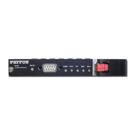
Model 6103
3U ForeFront
Alarm Card
SALES OFFICE
(301) 975-1000
TECHNICAL SUPPORT
(301) 975-1007
Advertisement
Table of Contents

Subscribe to Our Youtube Channel
Related Manuals for Patton electronics 6103


Summary of Contents for Patton electronics 6103
- Page 1 USER MANUAL Model 6103 3U ForeFront Alarm Card This is a Class A device and is intended for use in a light industrial environment. It is not intended nor approved for use in an industrial or residential environment. Part# 07M6103 SALES OFFICE Doc# 123011U Rev.
-
Page 2: Table Of Contents
CONTENTS Warranty Information ..............3 Radio and TV Interference (FCC Part15) ........3 CE Declaration of Conformity ............. 3 Authorized European Representative ......... 4 Service ..................4 Trademark Acknowledgements ..........4 General Information..............5 Product Features ................ 5 Description .................. 5 Operation ................... -
Page 3: Warranty Information
1.0 WARRANTY INFORMATION Patton Electronics warrants all Model 6103 components to be free from defects, and will—at our option—repair or replace the product should it fail within one year from the first date of shipment. This warranty is limited to defects in workmanship or materials, and does not cover customer dam- age, abuse or unauthorized modification. -
Page 4: Authorized European Representative
Patton Electronics' technical staff is also available to answer any questions that might arise concerning the installation or use of your Model 6103. Technical Service hours: 8AM to 5PM EST, Monday through Friday. In accordance with the requirements of council direc-... -
Page 5: General Information
• Auto-interlock mechanism for reliable connections to ForeFront chassis DESCRIPTION The Model 6103 Forefront Alarm Card is intended for use in Patton’s Model 6276, Model 6476, Model 6676, Model 6286, Model 6486, and Model 6686 Forefront Chassis Assemblies. The Model 6103 continuously monitors the chassis fan tray tachometer signals, the power supplies, and the chassis temperature for alarm conditions. -
Page 6: Operation
3.0 OPERATION Upon plugging the Model 6103 into the chassis, the unit will perform an LED self-test. After successful completion of this self-test the Model 6103 will be in normal operating mode and will monitor the fan tachometers, the power supply, and the temperature in the chassis on a continual basis. - Page 7 (N.O.) contact. If it is a minor alarm, the Model 6103 will connect pin 5 to pin 9. In the event of a major alarm, the Model 6103 will connect pin 2 to pin 6.
-
Page 8: Alarm Conditions
Fan monitor The Model 6103 monitors the fan tray tachometer signals. If a fan tray alarm signal is detected, the alarm card will illuminate the FAN LED. The Model 6103 will also illuminate either the MIN or the MAJ LED depend- ing on the severity of the alarm condition. -
Page 9: Temperature Alarm Conditions
Temperature Alarm Conditions The Model 6103 monitors the temperature in the chassis on the alarm card through an on-board temperature sensor. The following describes the conditions necessary to set a temperature alarm. Alarm Condition Temperature Major Alarm Ambient temperature in the chassis has reached 80°C (176°F) -
Page 10: Temperature Alarm Indications
PS LED and the MAJ LED. The alarm card will also activate the MAJOR relay by connecting pin 2 to pin 6 on the Form-C output. System Alarms The system alarms the Model 6103 can receive include: • System Clear Alarm • System Minor Alarm •... - Page 11 Table 1 summarizes all possible alarm conditions and the indicators that are active during these conditions. Table 1: Alarm Indicators TEMP MINOR MAJOR ALARM CONDITION RELAY RELAY Fan Minor Active Fan Major Active Power Supply Minor Active Power Supply Major Active Temperature Major Active...
-
Page 12: Female) Connector Pin Assignments
APPENDIX A DB-9 (FEMALE) CONNECTOR PIN ASSIGNMENTS Function Major Normally Closed Major Normally Open Minor Normally Closed Minor Normally Open Major Common Minor Common N.O. Minor Alarm contacts (showing no-alarm conditon) N.C. N.O. Major Alarm contacts (showing no-alarm conditon) N.C. Copyright ©...
Need help?
Do you have a question about the 6103 and is the answer not in the manual?
Questions and answers