Table of Contents
Advertisement
Quick Links
Notes
__________________________________________
__________________________________________
__________________________________________
__________________________________________
__________________________________________
__________________________________________
__________________________________________
__________________________________________
__________________________________________
__________________________________________
__________________________________________
__________________________________________
__________________________________________
__________________________________________
__________________________________________
Copyright © 2000 to 2006
Patton Electronics Co.
All rights reserved.
USER
MANUAL
MODEL 2710RC Series
NetLink-T1™
T1/Fractional T1 CSU/DSU
Rack Card
Part# 07M2710RC
Doc# 08607U2-002,
Rev. F
Revised 6/16/06
An ISO-9001
Certified Company
SALES OFFICE
(301) 975-1000
TECHNICAL SUPPORT
(301) 975-1007
http://www.patton.com
Advertisement
Table of Contents

Related Manuals for Patton electronics 2710RC Series


Summary of Contents for Patton electronics 2710RC Series
- Page 1 Notes USER __________________________________________ MANUAL __________________________________________ MODEL 2710RC Series __________________________________________ NetLink-T1™ __________________________________________ T1/Fractional T1 CSU/DSU Rack Card __________________________________________ __________________________________________ __________________________________________ __________________________________________ __________________________________________ __________________________________________ __________________________________________ __________________________________________ __________________________________________ __________________________________________ Part# 07M2710RC SALES OFFICE __________________________________________ Doc# 08607U2-002, (301) 975-1000 Rev. F TECHNICAL SUPPORT Revised 6/16/06 (301) 975-1007 Copyright ©...
-
Page 2: Table Of Contents
However, there is no guarantee that interference will not occur in a particular installation. If the Model 2710RC Series causes interference to radio or television reception, which can be determined by disconnecting the... -
Page 3: Equipment Attachment Limitations
1.3 EQUIPMENT ATTACHMENT LIMITATIONS (FIC) are 04DU9-BN, 04DU9-DN, 04DU9-1KN, and 04DU9-1SN. The Notice: The Industry Canada label identifies certified equipment. This Service Order Code (SOC) is 6.0N. certification means that the equipment meets telecommunications net- work protective, operational and safety requirements as prescribed in Facility Service Network... -
Page 4: General Information
Figure 1 shows the location of the DIP switches on the top of the board. • Made in USA 2.2 GENERAL PRODUCT DESCRIPTION The NetLink-T1™ Model 2710RC Series are single port T1/FT1 CSU/DSUs that provide high-speed WAN connectivity in a rack card package. Plugging directly into the serial WAN port of a switch, router or multiplexer, the NetLink-T1™... - Page 5 3.1.1 Switch S1 Line Framing Options: The table below shows the default configurations for Switch S1. A D4/Superframe: The D4 framing format, as specified in AT&T description of all S1 options follows this table. TR62411 is the standard in which twelve frames make up a S1 SUMMARY TABLE superframe.
- Page 6 NOTE 1: When using the Model 2710RC as a high-speed short Switch S2-2: Tx Clock Select range modem, one unit of the link must be configured in Switch S2-2 selects the clock that is used to accept the Transmit Internal/External Clock mode, and the opposite end unit must be Data from the DTE interface.
-
Page 7: Configuring The Rear Interface Card
3.2 CONFIGURING THE REAR INTERFACE CARD strap can either be on pegs 1 and 2, or on pegs 2 and 3. The Model 2710RC Series has three interface card options: the Sections 3.2.1, 3.2.2, and 3.2.3 describe the strap locations and possi- Model 1001RCM12548C (DB-25/RJ-48C), the Model ble settings for each rear card. - Page 8 Position 2&3 = DTE Shield (Pin 1) and FRGND Not Connected descriptions of each strap’s function. SGND & FRGND (JB4) In the connected position, this strap links DB-25 pin 7 (Signal DTE Shield (M/34 Pin A) & FRGND (JB3) Ground) and frame ground through a 100 ohm resistor. In the open In the connected position, this strap links M/34 pin A &...
-
Page 9: Software Configuration
are user configurable. 3.3.1 Setting the Card Address The table below provides an overview of interface strap functions The 2710RC contains two rotary switches (S3 and S4) which are used for the rear interface cards. Following the table overview are detailed to set the address of the card. - Page 10 Here is an example of a terminal emulator setup session. In The password prompt will be displayed as shown below. normal font are the various parameter types. In bold type are the values that should be used for best results. Your terminal program’s setup screen may differ from this one: Patton Electronics Baud rate: 9600...
- Page 11 HELPFUL HINTS 3.3.4 System Configuration The default System Configuration menu looks like this: To make a selection, key the highlighted letter that corre- The System Configuration options are described below: sponds to a menu selection. To execute the selection, type <Enter/CR> Select Save Changes from Main Menu after making modi- fications to any NetLink-T1™...
- Page 12 for a zero in bit 7 (out of 8) of a DS0 channel when the data in that channel are all zeros. This is a special form of AMI and is UNFRAMED:This is a special mode that allows you to achieve the compatible only with special equipment.
- Page 13 Line Build Out (dB): 0 – 133 feet, 0 dB (default) ESF Carrier Loops: Enabled (default) Options: 0 – 133 feet, 0 dB Options: Enabled, Disabled 133 – 266 feet 266 – 399 feet The ESF format provides the CO the ability to put the customer 399 –...
- Page 14 The NetLink-T1™ can be initialized via the configuration in the on- Front Panel Switches: Enabled (default) board permanent memory (EEPROM) or via the internal DIP switches (Switch). Once the unit is powered up, you may change the settings Options: Enabled, Disabled through the control port or the DIP switches.
- Page 15 The NetLink-T1™ is in remote loopback mode or sending TxUp The NetLink-T1 is sending the Loop-Up command to initi- a pattern. Local loopback is disabled. ate a CSU loopback LocP The NetLink-T1™ is in Local Loopback mode, and is TxDN The NetLink-T1 is sending the LoopDown command to sending a test pattern.
- Page 16 Severe Frame Error [SE] occurs when the framing error exceeds a Idle Indicates that NetLink-T1™ is not sending a pattern. certain threshold of errors. This may happen due to a disconnected line, an extremely noisy connection, or mismatched framing. Sending Indicates that NetLink-T1™ is sending a pattern. Loss of Sync [LOS] occurs when the T1 framer in the unit cannot synchronize itself to the received data stream.
- Page 17 Error Counters 3.3.6 Unit Information These error counters give a second-by-second snapshot of the The Unit Options screen looks like this (factory default): link performance. To clear all counters, press the [Backspace] key. If your keyboard does not have this key, you can press a two-key combi- nation to affect the same result: Hold down the [Ctrl] key and then press the [H] key.
- Page 18 Tx Data Clock Clear Errors This option selects the clock that is used to accept the Transmit The Model 2710RC records FIFO and Clock Slips and displays Data from the DTE interface. Standard DTE interfaces will transmit them on the right side of the screen. Slips can be an indication of data with respect to the External Clock.
-
Page 19: Installation
This section describes the functions of the Model 1001R14 rack replacement information. chassis, tells how to install front and rear Model 2710RC Series cards into the chassis, and how to connect to the twisted pair interface and 4.2 INSTALLING THE INTERFACE DRIVER BOARD the serial interface. -
Page 20: Connecting To A Dte Device
Push the Interface Driver Board gently onto the socket and re- 4.6 CONNECTING THE T1 INTERFACE install into the 1001 rack. The Network Line Interface is an eight position keyed modular jack configured as a RJ-48C. This interface will need to be configured to 4.3 INSTALLING THE MODEL 2710RC INTO THE CHASSIS match the line parameters (i.e. -
Page 21: Operation
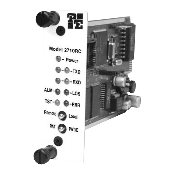
5.0 OPERATION Alarms may occur due to: Once the NetLink-T1™ is installed and configured properly it is • Loss of Synchronization ready to place into operation. This section describes the function of • Loss of Frame the LED indicators, and the use of the loopback and pattern test •... -
Page 22: Bit Error Rate (V.52) Diagnostics
to the local NetLink-T1™ in this test mode will be echoed (returned) Diagnostics/Statistics menu and toggle the <Spacebar> back to the user device (i.e., characters typed on the keyboard of a ter- until “RL” appears next to the Remote Loop option.; minal will appear on the terminal screen). -
Page 23: Appendix A - Specifications
QRSS Initiates a built-in 2 bit pseudo-random APPENDIX A pattern generator and detector. PATTON NETLINK-T1 MODEL 2710RC To perform a V.52 test, follow these steps: SPECIFICATIONS Activate the local loopback or remote loopback diagnostic. WAN Speed: 1.544 Mbps Activate the test pattern. This may be done in one of two ways: WAN Connection: RJ-48C Enter... -
Page 24: Appendix B - Cable Recommendations
1001R14P Rack 14 Slot 2U Chassis Only 1001R14P/R48V Rack 14 Slot 2U w/Dual Universal Input To gain optimum performance from the Model 2710RC Series, 48VDC Power Supplies please keep the following guidelines in mind: 1001R14P/RUIA Rack 14 Slot 2U w/Dual Universal Input 90-260VAC Power Supplies •... - Page 25 APPENDIX D APPENDIX E PATTON NETLINK-T1™ MODEL 2710RC PATTON NETLINK-T1™ MODEL 2710RC T1 INTERFACE PIN ASSIGNMENT V.35 INTERFACE PIN ASSIGNMENT RJ-48C T1 (DS0) Network Interface M/34 Connector, Terminal Interface (Female Modular Jack) Pin # Signal GND (Earth Ground/Shield) SGND (Signal Ground) Pin # Signal RX Data (RING)
- Page 26 APPENDIX E APPENDIX E (continued) (continued) PATTON NETLINK-T1™ MODEL 2710RC PATTON ELECTRONICS MODEL 2710 INTERFACE PIN ASSIGNMENT EIA-530 INTERFACE PIN ASSIGNMENT X.21 Interface DB-25 Female Connector, Terminal Interface (DB-15 Female Connector) (DTE /DCE Configuration) Pin # Signal FG (FrameGround) Pin # Signal TD (Transmit Data-A, DTE Source) 1.
Need help?
Do you have a question about the 2710RC Series and is the answer not in the manual?
Questions and answers