Trane Tracer MP503 Installation And Operation Manual
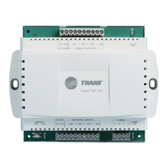
Input/output module
Hide thumbs
Also See for Tracer MP503:
- Manual (8 pages) ,
- Installation, operation and maintenance manual (32 pages)

Related Manuals for Trane Tracer MP503


Summary of Contents for Trane Tracer MP503
- Page 1 Installation and Operation Tracer MP503 Input/Output Module CNT-SVX09B-EN April 2005...
- Page 2 CNT-SVX09B-EN...
- Page 3 Although Trane has tested the hardware and software described in this guide, no guarantee is offered that the hardware and software are error free. Trane reserves the right to revise this publication at any time and to make changes to its content without obligation to notify any per- son of such revision or change.
- Page 4 NOTICE: Warnings and Cautions appear at appropriate sections throughout this manual. Read these carefully: WARNING Indicates a potentially hazardous situation, which, if not avoided, could result in death or serious injury. CAUTION Indicates a potentially hazardous situation, which, if not avoided, may result in minor or moderate injury. It may also be used to alert against unsafe practices.
-
Page 5: Table Of Contents
Mounting recommendations ........10 Chapter 4 Applications of the Tracer MP503... . . 11 Inputs . - Page 6 Tracer MP503 circuit board........26...
-
Page 7: Chapter 1 Overview And Specifications
0–20 mA, or 0–10 Vdc, as well as four binary outputs. Storage environment If a Tracer MP503 I/O module is to be stored for a substantial amount of time, store it in an indoor environment that meets the following requirements: Temperature: –40°... -
Page 8: Clearances
Chapter 1 Overview and specifications Metal-cover model dimensions For complete dimensional drawing, see . Height: 9.0 in (25 mm) • Width: 10.37in. (263 mm) • Depth: 2.25 in. (58 mm) • Clearances For wiring, ventilation, and maintenance, provide the following minimum clearances for the module, : Plastic-cover model (see Figure 1 on page 3) - Page 9 Operating environment Figure 1. MP503 plastic-cover model dimensions and clearances 1 in. (25 mm) 4 in. 4 in. (102 mm) (102 mm) 4 in. (102 mm) 6.31 in. 5.625 in. 6.875 in. (160 mm) (143 mm) (175 mm) 5.375 in. (137 mm) 2 in.
-
Page 10: Agency Listing/Compliance
Chapter 1 Overview and specifications Storage environment If you are storing a Tracer ZN517 unitary controller for a substantial amount of time, store it in an indoor environment that meets the following requirements: • Temperature: From –40° to 185°F (–40° to 85°C) •... -
Page 11: Chapter 2 General Wiring Information
Chapter 2 General wiring information This chapter provides specifications and general information about wir- ing the Tracer MP503 I/O module. The module requires wiring for: Input/output terminals • AC power to the module • Communication-link wiring, if the module is to communicate with a •... -
Page 12: Ac-Power Wiring
The recommended wire for ac power is 16 AWG (1.3 mm )copper wire. All wiring must comply with National Electrical Code and local codes. The ac-power connections are in the top left corner of the Tracer MP503 I/ O module (see Figure 3 on page 7). CNT-SVX09B-EN... - Page 13 (20–30 Vac). The transformer must be sized to provide adequate power to the Tracer MP503 I/O module (10 VA) and output devices, including relays, to a maximum of 12 VA per output utilized. The Tracer MP503 may be powered by an existing transformer integral to the controlled equipment, provided the transformer has adequate power available and proper grounding is observed.
-
Page 14: Communication-Link Wiring And Addressing
Chapter 2 General wiring information Communication-link wiring and addressing The Tracer MP503 I/O module communicates with the BAS and with other devices through a LonTalk communication link. IMPORTANT For important instructions on network wiring, refer to the Tracer Sum- mit Hardware and Software Installation guide (BMTX-SVN01A-EN). -
Page 15: Chapter 3 Mounting The Module
Where public access is restricted to minimize the possibility of tam- • pering or vandalism Operating environment requirements Operate a Tracer MP503 I/O module in an environment that meets the following requirements: Temperature: –40°F to 158°F (–40°C to 70°C) •... -
Page 16: Mounting Recommendations
Chapter 3 Mounting the module Mounting recommendations IMPORTANT Leave the cover on when mounting the Tracer MP503 I/O module to avoid the possibility of damaging the circuit board during installation. Mounting recommendations are as follows: Mount the module in any direction, other than with the front of the •... -
Page 17: Chapter 4 Applications Of The Tracer Mp503
Inputs The Tracer MP503 has four inputs. Each input can be configured to be binary, thermistor, 0–20 mA, or 0–10 Vdc. You may have any mixture of these input types connected to the module. The factory-default input type is thermistor. -
Page 18: 0-20 Ma Inputs
To power these sensors, 24 Vdc is available from the Tracer MP503 circuit board. See Figure 5 on page 13 for wiring details. 0–10 Vdc inputs The Tracer MP503 can read a value from a sensor that provides a 0– 10 Vdc signal. IMPORTANT If you are using a sensor with a smaller range (such as 2–10 Vdc or 6–... -
Page 19: Wiring Requirements And Options
Wiring requirements and options Wiring requirements and options Figure 5 shows the wiring of each type of input on the Tracer MP503 I/O module. The figure also shows the wiring for a typical binary output. Figure 5. Input/output terminal wiring for the Tracer MP503 I/O module... - Page 20 Chapter 4 Applications of the Tracer MP503 CNT-SVX09B-EN...
-
Page 21: Chapter 5 Network Variable Bindings
Chapter 5 Network variable bindings This chapter describes how to use network variable bindings in Tracer MP503 I/O module applications. Overview The LonTalk communication protocol allows data to be shared between devices (stand-alone or with a BAS) on a LonTalk network. This is called peer-to-peer communication. -
Page 22: Tracer Mp503 Bindings
Chapter 5 Network variable bindings Tracer MP503 bindings The principal purposes of a Tracer MP503 I/O module are to gather data (sensor readings) for use by a BAS or peer device and to allow a BAS or peer device to control Tracer MP503 binary outputs. Therefore, the use of bindings is very important in Tracer MP503 applications. -
Page 23: Sending Data
A network variable output (nvo) sends data to other devices on the Lon- Talk network. The network variable outputs (including their SNVTs) that are commonly used in Tracer MP503 bindings are shown in Table 2. Table 2. Tracer MP503 network variable outputs... - Page 24 Chapter 5 Network variable bindings Table 2. Tracer MP503 network variable outputs Variable name Data type Description nvoCurrent3 SNVT_amp_mil Universal input 3 sta- Indicates the value of universal input 3 if it is tus output configured as 0–20 mA. If universal input 3 is not configured as 0–20 mA, this output is -3276.8.
-
Page 25: Examples Of Network Variable Bindings
In this example, four different sensors are connected to a Tracer MP503. A thermistor reading the outside air temperature is connected to univer- sal input 1 on the Tracer MP503. A 4–20 mA sensor reading the outside air humidity is connected to universal input 2. Two binary inputs from a fire panel (Alarm Status and Fire Panel Trouble) are connected to univer- sal input 3 and universal input 4, respectively. - Page 26 Chapter 5 Network variable bindings Table 3 shows the bindings needed. Table 3. Bindings for example 1 Network variable output on the Network variable input on Tracer MP503 the Tracer MP581 nvoTemperature1 binds to nviTemp01 nvoCurrent2 binds to nviCurrent_mA01 nvoBIP3Status...
-
Page 27: Example 2: Display Sensor Readings From A Tracer Mp503 On Two Different Tracer Mp581 Operator Displays
Use the Rover service tool to create bindings. (See the Rover Operation and Programming guide, EMTX-SVX01B-EN.) Using the Rover service tool, select the network variable from the Tracer MP503 and then select the second Tracer MP581. The Rover service tool shows you only the vari- ables in Tracer MP581 #2 of the SNVT that matches the variable you selected in the Tracer MP503. -
Page 28: Example 3: Control A Binary Output On The Tracer Mp503 From A Tracer Mp581
AHU. The AHU and the exhaust fan follow the same schedule; for example, whenever the AHU runs, the exhaust fan runs. Bind an nvo on the Tracer MP581 to an nvi on the Tracer MP503 so the AHU and exhaust fan run together. Figure 8 shows the LonTalk network for this example. -
Page 29: Example 4: Use A Sensor Reading On A Tracer Mp503 To Control A Pump Vfd On A Tracer Mp581
Use the Rover service tool to create bindings. (See the Rover Operation and Programming guide, EMTX-SVX01B-EN.) Using the Rover service tool, select the network variable from the Tracer MP503 and then select the Tracer MP581. The Rover service tool shows you only the variables in... - Page 30 Chapter 5 Network variable bindings the Tracer MP581 of the SNVT that matches the variable you selected in the Tracer MP503. Table 6 shows the bindings needed. Table 6. Bindings for example 4 Network variable output on Network variable input on the...
-
Page 31: Chapter 6 Status Indicators For Operation And Communication
This chapter describes the operation and communication status indica- tors on the Tracer MP503 I/O module, including: A description of the location and function of the Service Pin button • and the light-emitting diodes (LEDs) located on the module A complete list of the diagnostics that can occur, their effect on mod- •... -
Page 32: Tracer Mp503 Circuit Board
Tracer MP503 circuit board Figure 10 shows the location of the Service Pin button, the Neuron ID and label, and the LEDs on the Tracer MP503 I/O module circuit board. Figure 10. Tracer MP503 I/O module circuit board Binary output 4... -
Page 33: Interpreting Leds
Interpreting LEDs Interpreting LEDs Service LED The red Service LED (see Figure 10 on page 26) indicates whether the module is capable of operating normally. See Table 7. Table 7. Red Service LED LED activity Explanation LED is off continuously The module is operating normally. -
Page 34: Lontalk Led
MP503. Binary output LEDs Four green LEDs on the Tracer MP503 circuit board indicate the status of the four binary outputs. The location of each LED is shown in Figure 10 on page 26. Table 10 shows the LED number for each binary output. -
Page 35: Diagnostics
Diagnostics Diagnostics Diagnostics do not affect the operation of the Tracer MP503. When the diagnostic clears, the module resumes normal operation. Table 12 lists the diagnostics for the Tracer MP503. All diagnostics generated by the Tracer MP503 are automatic (non-latch- ing) diagnostics. - Page 36 Chapter 6 Status indicators for operation and communication CNT-SVX09B-EN...
-
Page 37: Chapter 7 Troubleshooting
This chapter outlines some general troubleshooting steps that should be performed if there is a problem with the operation of the equipment con- trolled by the Tracer MP503. This chapter describes some common prob- lems; however, it cannot describe every possible problem. Troubleshooting that involves accessing live electrical devices must be conducted only by a properly trained and authorized electrician or trained technician. -
Page 38: Initial Troubleshooting
Step 3 Use your meter (set to measure ac voltage) to measure the voltage across the Tracer MP503 cir- ac power terminals on the Tracer MP503 (with ac wires connected). See cuit board prob- Figure 3 on page 7. If the voltage is approximately 24 V (20–30 V) on the terminals, the board is receiving adequate input power. -
Page 39: Binary Output (Relay Output) Troubleshooting
Look at the status LED for the binary output you are troubleshooting. (See Wiring problem “Binary output LEDs” on page 28.) If the LED is on, the Tracer MP503 is energizing its output relay. Use your meter (set to measure ac voltage) to measure the voltage across the binary output terminals you are troubleshooting on the Tracer MP503. - Page 40 LonTalk network that includes this Tracer MP503. (The Bindings button will be disabled if the Tracer MP503 is the only device currently on the network.) Is this binary output bound? Is it bound to more than one network device? If it is bound to two devices, one may be commanding the binary output on while the other commands it off.
-
Page 41: Universal Input Troubleshooting
— Rover service tool, and select the Tracer MP503 you are troubleshooting from the Active Group Tree. The device plug-in for the selected Tracer MP503 will appear with the Status screen displayed in the workspace. See the Rover Operation and Programming guide (EMTX-SVX01B-EN) for more information. - Page 42 The voltage should be 16.00–18.00 Vdc (see Table 22 on page 38). If the voltage is not in that range, the Tracer MP503 has a circuit board problem. CNT-SVX09B-EN...
- Page 43 The voltage should be 0.10–0.13 Vdc (see Table 22 on page 38). If the voltage is not in that range, the Tracer MP503 has a circuit board problem. Figure 12. Voltage measured across terminals vs. input current Current (mA) Table 21.
- Page 44 Chapter 7 Troubleshooting Table 22. Voltage measurements at universal inputs (no sensor connected) Input type Expected value Acceptable range Thermistor 5.00 Vdc 4.75 to 5.25 Vdc Binary 17.00 Vdc 16.00 to 18.00 Vdc 0–20 mA 0.116 Vdc 0.100 to 0.130 Vdc 0–10 Vdc 3.43 Vdc 3.10 to 3.80 Vdc...
-
Page 45: Index
Analog inputs 0–10 Vdc inputs, 4, 2 Fan speed switch, 4 0–20 mA inputs, 4, 2 FCC, Agency listing/compliance Applications of the Tracer MP503, 1–4 Input devices, 4 BAS communication, 4 Input/output terminal wiring, 1, 3 Binary inputs, 4, 1 Inputs... - Page 46 3 Terminal wiring, 1 Termination resistors, 4 Thermistor inputs, 4, 1 Operating environment, 1 Troubleshooting, 5, 6 Output devices, 4 Tracer MP503 I/O module Outputs, 2 Circuit board, 2 see also Binary outputs Description of, 1 Location of LEDs, 2 Mounting, 1–2...
Need help?
Do you have a question about the Tracer MP503 and is the answer not in the manual?
Questions and answers